Powertrain for aircraft in runways
Aim: To design a Powertrain for aircraft in runways after studying aircraft operation, parts and terminologies in detail.The study is divided into 7 parts
- Understand about weight terminology in aircrafts
- Understand about aerodynamic forces and relative velocities to define air and ground speed
- Why the engine power is not used to move the aircraft along runway
- Understanding the neccessity of a tower on ground
- Learn about take-off power, tyre design, rolling resistance, tyre pressure, brake forces when landing.
- With necessary assumptions, calculate the force and power required to push / pull an aircraft by a towing vehicle.
- Design of an electric powertrain
1. Search and list out the total weight of various types of aircraft.
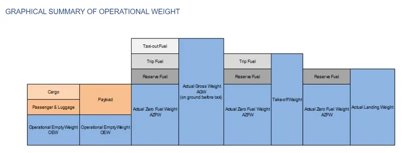
- a) The term called as manufacturer's empty weight (MEW) (also known as manufacturer's weight empty (MWE)) represents the weight of the aircraft "as built" structure. This includes weight of the structure, power plant, furnishings, installations, systems, and other equipment which are considered as considered an integral part of an aircraft before additional operator items are added for operation.
- b) The aircraft gross weight (also known as the all-up weight and abbreviated AUW) is the total aircraft weight at any moment be it during the flight or ground operation of the aircraft.
- c) The MEW and the operator’s items are summed up to the Operational Empty Weight (OEW). The OEW is usually fixed for a specific aircraft and only gets changed during maintenance or operational changes.
- d) The operator’s items are:
- fluids necessary for aircraft operation (engine oil and coolant, water, unusable fuel)
- the water for galleys and lavatories
- aircraft documentation
- passenger seats (and the life vests)
- galley structure
- catering emergency equipment
- aircraft crew and their luggage.
- standard items necessary for full operations
- e) Operational empty weight (OEW)- is the empty weight that is used in the flight simulator or the usual planning software.)An aircraft's gross weight will decrease during a flight due to fuel and oil consumption. An aircraft's gross weight may also vary during a flight due to payload dropping or in-flight refuelling.
- f) Actual zero fuel weight (AZFW)- When the payload is added to empty plane weight we get the Actual Zero Fuel Weight. payload includes:
- the passengers weight (the standard weights used defined by ICAO respectively)
- the passengers luggage’s weight
- the cargo weight
- g) Actual gross weight- n addition to the actual zero fuel weight, we add the fuel required for the flight and we get the Actual Gross Weight (AGW).An aircraft's gross weight may also vary during a flight due to payload dropping or in-flight refueling.
- h) Take off weight-Fuel burn during taxi operation to the departure runway reduces the gross weight. At the holding point, we have the Actual Take-off Weight (ATOW) which is used for take-off performance calculation.
- i) The maximum takeoff weight (also known as the maximum brake-release weight) is the maximum weight authorized at brake release for takeoff, or at the start of the takeoff roll.
- j) With the calculation of fuel consumption during flight, we can calculate the Estimated Landing Weight (ELW) which is used for landing performance calculation at the destination.
- The diagram conveys how the weights are distributed to above expressed types
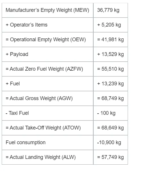
- For example individual weight distributions of a typical aircraft (AIRBUS 319)is mentioned below.
- The weight of different airliners are mentioned below with the abbrevations of weight as:
- MTOW = Maximum take-off weight, MLW = Maximum landing weight, TOR = Take-off run (SL, ISA+15°, MTOW), LR = Landing run (SL, ISA+15°, MLW)
-
Type MTOW [kg] MLW [tonnes] TOR [m] LR [m] ICAO category FAA category Antonov An-225 640,000 591.7 3500 Heavy Super Scaled Composites Model 351 Stratolaunch 589,670 3660 Heavy Super Airbus A380-800 575,000 394 3100 1930 Super Super Boeing 747-8F 447,700 346.091 3100 1800 Heavy Heavy Boeing 747-8 443,613 306.175 3100 Heavy Heavy Boeing 747-400ER 412,770 295.742 3090 Heavy Heavy Antonov An-124-100M 405,060 330 2520 900 Heavy Heavy Boeing 747-400 396,900 295.742 3018 2179 Heavy Heavy Lockheed C-5 Galaxy 381,000 288.417 2530 1494 Heavy Heavy Boeing 747-200 377,840 285.700 3338 2109 Heavy Heavy Boeing 747-300 377,840 260.320 3222 1905 Heavy Heavy Airbus A340-500 371,950 240 3050 2010 Heavy Heavy Airbus A340-600 367,400 256 3100 2100 Heavy Heavy
- 2. Is there any difference between ground speed and airspeed?
-
Whenever an object moves through a fluid medium aerodynamic forces are generated.generated by an object moving through a fluid (liquid or gas). To obtain a lift it is essential for a body to move through air with air moving around it creating a aerodynamic force. This is where the term relative velocity comes into picture. This can be understood by considering a reference point. This can be on the ground.For a reference point picked on the ground, the air moves relative to the reference point at the wind speed. Wind speed is a vector quantity and depends on which direction across which it blows.
-
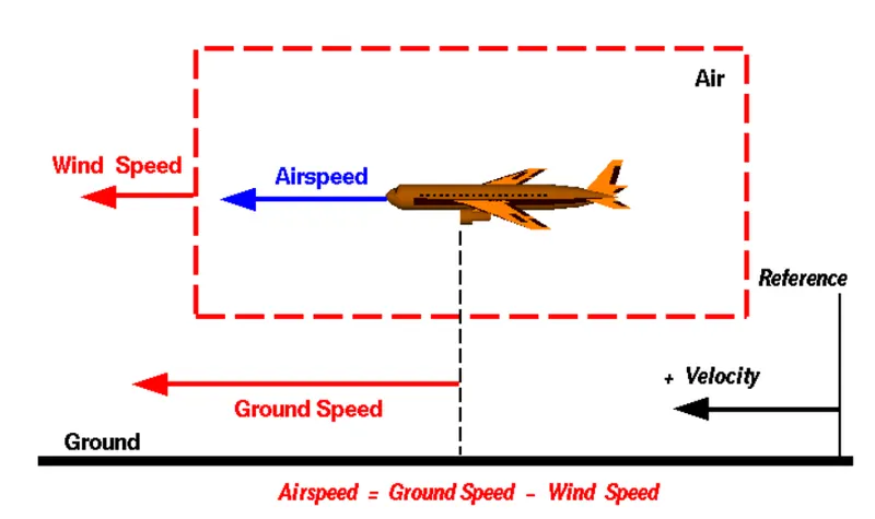
This can be understood with an example.Consider the attached figure
-
A 20 mph wind from the west is different from a 20 mph wind from the east. The wind speed has many components in multiple directions(north-south, east-west, and up-down).The above figure considers only velocities that acts along aircraft's flight path. A positive velocity is defined to be in the direction of the aircraft's motion.The crosswinds which occur perpendicular to the flight path but parallel to the ground, and upward and downward winds , which occur perpendicular to the ground are neglected
-
Ground Speed-For a reference point picked on the ground, the aircraft moves relative to the reference point at the ground speed. Ground speed too is a vector quantity so a comparison of the ground speed to the wind speed must be done according to rules of vector addition
-
Airspeed- Relative velocity plays an important role in the generation of lift.The important quantity in the generation of lift is the relative velocity between the object and the air, which is called the airspeed. Airspeed cannot be directly measured from a ground position, but must be computed from the ground speed and the wind speed. Airspeed is the vector difference between the ground speed and the wind speed.
-
Airspeed = Ground Speed - Wind Speed
3. Why is it not recommended to use aircraft engine power to move it on the ground at Airport?
- The term Aircraft Ground Running is usually used to describe the operation engines of an aircraft, when they are on the ground.
- This is done for the purpose of functionally checking the operation of either engines or aircraft systems
- Commercial airliners made by boeing are fitted with engines rated from 18,000 to nearly 100,000 lb of thrust. Such thrust levels provide for safe takeoff, flight, and landing over a wide range of temperatures, altitudes, gross weights, and payload conditions.
- On usaeg for ground run the exhaust wake from these engines can pose hazards in commercial airport environments.
- Ground running can pose a serious threat when there is loss of control
- The control faults may occur from those persons occupying the pilot seats in the flight deck.
- In most cases, such persons will be maintenance personnel holding specific company-issued approval for the required tasks.
- The consequences of loss of control during taxi or towing are the same. Ground run of of such high powered give rise to unwanted consequences. This process of ground run also called as static run can cause issues related to unintended movement of the aircraft during engine running causing a loss of control especially during high power engine running.
- Damage can occur to the aircraft itself or to airside structures or other aircrafts
- Operators and airport authorities must carefully consider these hazards which can lead to potential for injury to people and damage to or caused by baggage carts, service vehicles, airport infrastructure and other airplanes.
- High engine thrust during maintenance activity can cause considerable damage to airplanes and other elements in the airport environment.
- The image attached below demonstrates about exhaust wake,reverse idle etc
- 4. How an aircraft is pushed to the runway when it's ready to take off.
- - In aviation, pushback is an airport procedure during which an aircraft is pushed backwards away from an airport gate by external power. Pushbacks are carried out by special, low-profile vehicles called pushback tractors or tugs.
-
Almost all commercial and passenger airliners are capable of reverse motion on ground using reverse thrust
-
This is not preffered as it might result in following:
-
a) The jet blast from the engines can damage the terminal building and nearby equipment. It can even throw away people standing nearby.
-
b) Engines can blow sand and debris
-
c) Engines can suck in sand and debris which can cause serious damage to the engine
-
d) It is easier for the truck driver to see the surroundings better than the pilot sitting in the cockpit with limited windows.
-
e)The pushback truck driver knows the airport better than the pilot.
-
f) The plane engines are very loud. This noise can add up substantially when multiple planes are moving around the airport. It won't be a pleasant experience for people sitting inside the terminal, as most people don't even like the sound of powerful motor-bikes.
-
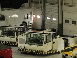
The common pushback comes in various shapes and sizes, and either runs off battery-supplied electricity, or diesel fuel. Some are open-wheel, while others have enclosed cabs.Pushbacks all have the same basic functions. The driver sits behind a big steering wheel, while wearing a headset to communicate with the pilots. The headset can either be wireless, or connected directly into the communications box on the nose of the plane by a long together.
-
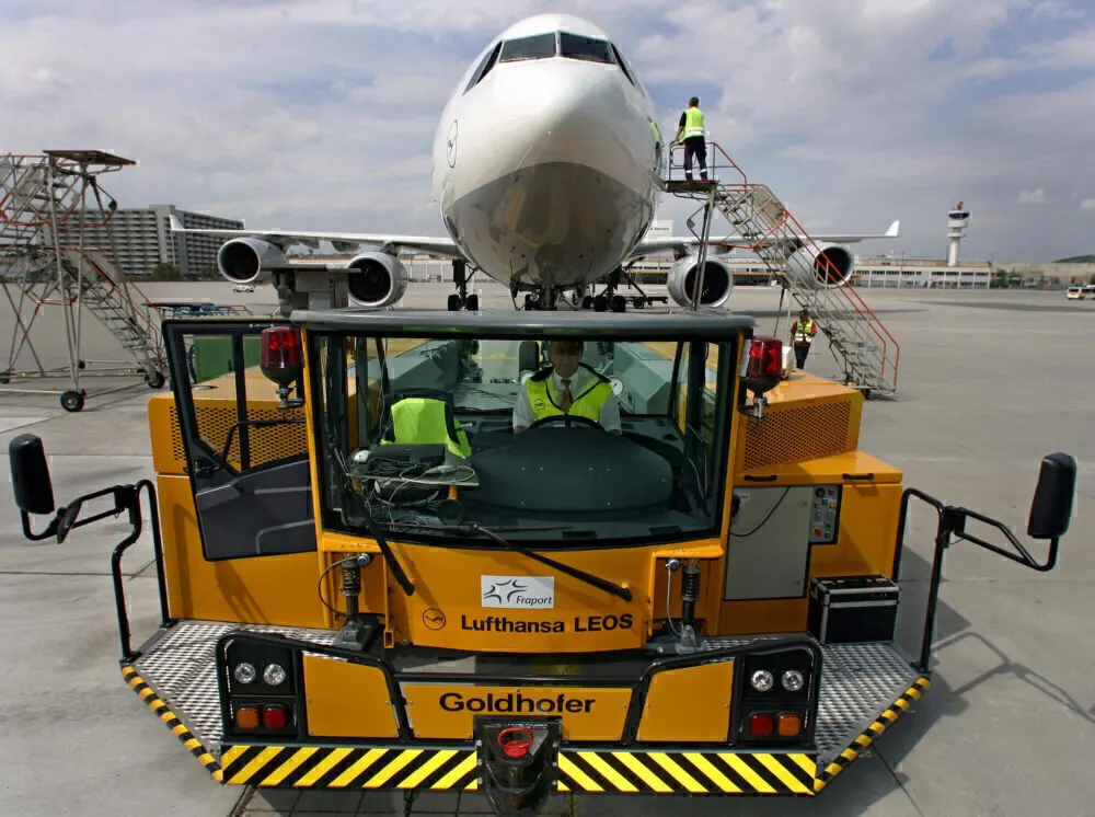
For towing large airliners pushback tractors are needed.These tractors must have a low profile design such that it fits under aircraft nose.
-
To develop the neccessary tractive effot the push back tractors are come and have a built in ballast.
-
-
A pushback tractor used to move large aircraft tends to weigh up to 54 tonnes
-
It is capable of providing a drawbar pull of 334 kN
-
The level of visibility can be increasedas the driver’s cabin can often be raised during the reversing process, whilst it can usually be lowered to ensure that it fits underneath aircraft, too.
-
There are two different types of pushback tractors available: conventional and towbarless (TBL).A tow bar is used within conventional tugs in order to connect the tug to the nose landing gear of the aircraft, whereas tow barl ess (TBL) tractors have the capability of scooping up the nose landing gear, lifting it off the ground in the process, meaning that there is no need for a towbar.
-
Conventional push back tractor Towbarless push back
-
- 5. Learn about take-off power, tyre design, rolling resistance, tyre pressure, brake forces when landing.
- Take-off power
- Take off is the phase of flight in which an aerial vehicle leaves the ground and becomes airborne. For aircraft that take off horizontally, this is a transition from moving along the ground for a particular distance on a runway to air
- For light aircrafts, during takeoff full power is used .
- Large transport category(airliner) aircraft like cargo flights may use a reduced power for takeoff, where less than full power is applied in order to prolong engine life, reduce maintenance costs and reduce noise emissions.
- At times in emergency cases where there is a need of improved engine performance engine power is boosted up. Especially in case of piston engines are routinely run up at high power to see the occurance of engine-related problems.
- Tyre design
- An aircraft tire is designed to withstand extremely heavy loads for short durations. The number of tires required for aircraft increases with the weight of the aircraft, as the weight of the airplane needs to be distributed more evenly. Aircraft tire tread patterns are designed to facilitate stability in high cross wind conditions, to channel water away to prevent hydroplaning, and for braking effect.
- The major design philosophy of an aircraft tire, as compared to other tire types such as passenger and truck tires, is that they are designed for intermittent operation. Because of this design feature and to allow the lowest possible ground bearing pressure, the aircraft tire operates at much higher deflections than other tire types
- Two types of tires are used in aircraft applications based on plies — bias-ply tires and radial tires.
- Radial ply tires - these tyres feature a flexible casing which is constructed of rubber-coated ply cords which extend around the beads and are substantially at 90° to the centerline of the tread. The casing is stabilized by an essentially inextensible circumferential belt.
-
- Bias ply tires - these tyres feature a casing which is constructed of alternate layers of rubber-coated ply cords which extend around the beads and are at alternate angles substantially less than 90° to the center line of the tread.
- Structure of a Bias ply tyre:
- Tread: The tread is made of rubber mixed with other additives to obtain the desired level of toughness, durability, and resistance to wear. The tread pattern is designed to aircraft operational requirements, with the ribbed tread design used widely due to its good traction under varying runway conditions.
- Sidewall: The sidewall is a protective layer of rubber that covers the outer casing ply. It extends from the tread edge to the bead area.
- Tread Reinforcing Ply: One or more layers of fabric that strengthens and stabilizes the tread area for high-speed operation. It also serves as a reference for the buffing process when tires are retreaded.
- Buff Line Cushion: The buff line cushion is made of rubber compound to enhance the adhesion between the tread reinforcing ply and the breakers or casing plies. It is of sufficient thickness to allow for the removal of the old tread when the tire is retreaded.
- Breakers: Breakers are reinforcing plies of rubber-coated fabric placed under the buff line cushion to protect casing plies and strengthen and stabilize the tread area. They are considered an integral part of the casing construction.
Casing Plies: Alternate layers of rubber-coated fabric (running at opposite angles to one another) provide the strength of the tire. - Wire Beads: Hoops of high tensile strength steel wire that anchor the casing plies and provide a firm mounting surface on the wheel. The outer edge of the bead that fits against the wheel flange is called the bead heel. The inner bead edge is called the bead toe.
- Apex Strip: A wedge of rubber affixed to the top of the bead bundle.
Flippers: Layers of rubberized fabric that help anchor the bead wires to the casing and improve the durability of the tire. - Ply Turnips: The casing plies are anchored by wrapping them around the wire beads, thus forming the ply turnups.
Chafer: A protective layer of rubber and/or fabric located between the casing plies and wheel to minimize chafing.
Liner: In tubeless tires, the liner is a layer of low permeability rubber that acts as a built-in tube and restricts gas from diffusing into the casing plies. In tube-type tires, a thinner liner is used to prevent tube chafing against the inside ply. - Structure of a Radial ply tyre:
- They have fewer components in their construction and are lighter than similarly sized bias-ply tires. Components that differ from bias-ply construction as follows:
- Overlay: A layer of reinforcing rubber-coated fabric placed on top of the belts to aid in high-speed operation.
Belt Plies: A composite structure that stiffens the tread area for increased landings. The belt plies increase the tire strength in the tread area. - Casing Plies: As in bias-ply tires, the casing plies are layers of rubber-coated fabric. However, unlike those in bias plies that run at opposite angles to one another, radial plies run radially from bead to bead.
Chippers: The chippers are layers of rubber-coated fabric applied at diagonal angles that improve the durability of the tire in the bead area. - Based on the method for containing the inflation gas the tyres can be:
- Tube-type tyres - these require tubes for inflation retention.
- Tubeless tyres - these do not require tubes. They are constructed with an innerliner (integral rubber lining that is engineered to prevent the diffusion of the inflation gas into the casing.).
- Tyre pressure:
- The typical airliner tire can handle a 38-ton load. It can meet the ground 500 times before needing a re-tread.
- a Boeing 737 rides on 27x7.75 R15 rubber. In English, that means it is 27 inches in diameter, 7.75 inches wide, and wrapped around a 15-inch wheel. The sidewalls aren't terribly thick, and the strength of the tire lies in the cords embedded below the tread
-
The tires do not use the typical compressed air we would use from a fuel station supply or a home air compressor.
-
Aviation tires are made of a much stronger compound than what we use for the auto industry and in fact, they use nitrogen gas to inflate the tires, as opposed to compressed air.
-
This provides the additional strength to the tires in general, to support the tremendous weight they carry moving the plane or on take off and for landing.
-
The average pressure they run in the tires is between 200–220 PSI, it again depends on the model aircraft, (Automobiles run 30–40 psi on average)
- An aircraft tire or tyre is designed to withstand extremely heavy loads for short durations.
- Each of the twelve Boeing 777-300ER main tires is inflated to 220 psi (15 bar; 1,500 kPa), weighs 120 kg (260 lb), has a diameter of 134 cm (53 in) and is changed every 300 cycles while the brakes are changed every 2000 cycles. Each tire is worth about $5,000. Aircraft tires generally operate at high pressures, up to 200 psi(14 bar; 1,400 kPa) for airliners, and even higher for business jets. The main landing gear on the Concorde was typically inflated to 232 psi (16.0 bar), whilst its tail bumper gear tires were as high as 294 psi (20.3 bar). The high pressure and weight load on the Concorde tyres were a significant factor in the loss of Air France Flight 4590.
- Tests of airliner aircraft tires have shown that they are able to sustain pressures of maximum 800 psi (55 bar; 5,500 kPa) before bursting. During the tests, the tires have to be filled with water, to prevent the test room being blown apart by the energy that would be released by gas when the tire bursts.
- Aircraft tires are usually inflated with nitrogen to minimize expansion and contraction from extreme changes in ambient temperature and pressure experienced during flight. Dry nitrogen expands at the same rate as other dry atmospheric gases (normal air is about 80% nitrogen), but common compressed air sources may contain moisture, which increases the expansion rate with temperature
- Brake forces:
- While touching the ground aircraft generally employs disc brakes. These brakes are operated hydraulically or pneumatically. Nowadays the brakes are activated using top section of the rubber pedals whereas in some older aircraft, the bottom section is used instead. Levers are used in a few aircraft.
- Most aircraft are capable of differential braking.
- Electric brakes:
- For example, the brake system on the 787 Dreamliner is controlled by the pilots pressing the tops of the rudder pedals under their feet according to the rate of braking which they require.
- This sends an electronic signal to the Left and Right Brake System Control Units (BSCUs).
- Upon this signals are sent to the four Electronic Brake Actuator Controllers (EBAC) which control the rate of braking on the wheels.
- Each wheel has four Electric Brake Actuators (EBA), a kind of piston that presses against the carbon brake discs which is shown below.
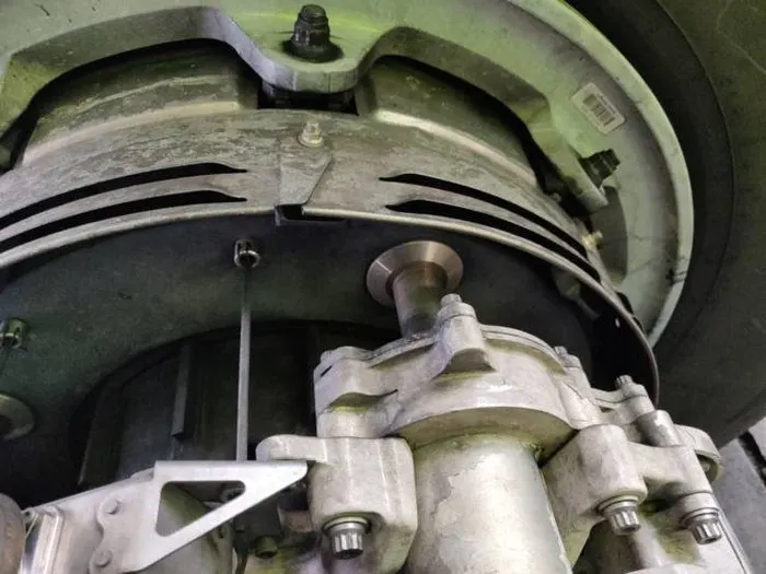
- The brake disks comprise of two parts. Rotors that are connected to the wheel by drive tabs
- The drive tabs are in contact with the inside of the wheel, they spin at the same speed.
- Depending on the brake manufacturer, there are either four or five of these rotors on each brake assembly.
- The second part of the disks are the stators. These sit around each rotor and are fixed in place and are immobile.
- As the wheel turns, the rotors spin round inside the stators. When the brakes are applied, the four EBAs apply pressure to the first stator. This, in turn, squeezes the stationary stators up against the spinning rotors and it’s this friction that slows the wheel down.
- Rolling resistance:
- Rolling resistance sometimes called rolling friction or rolling drag is the force resisting the motion when a body rolls on a surface. It is mainly caused by non-elastic effects; that is, not all the energy needed for deformation (or movement) of the wheel, roadbed, etc., is recovered when the pressure is removed.
- Rolling resistance is often expressed as a coefficient times the normal force. This coefficient of rolling resistance is generally much smaller than the coefficient of sliding friction.
- 6) With necessary assumptions, calculate the force and power required to push / pull an aircraft by a towing vehicle.
- The aircraft considered is Airbus 310 and. The selection of tow vehicle is done on basis of :
-
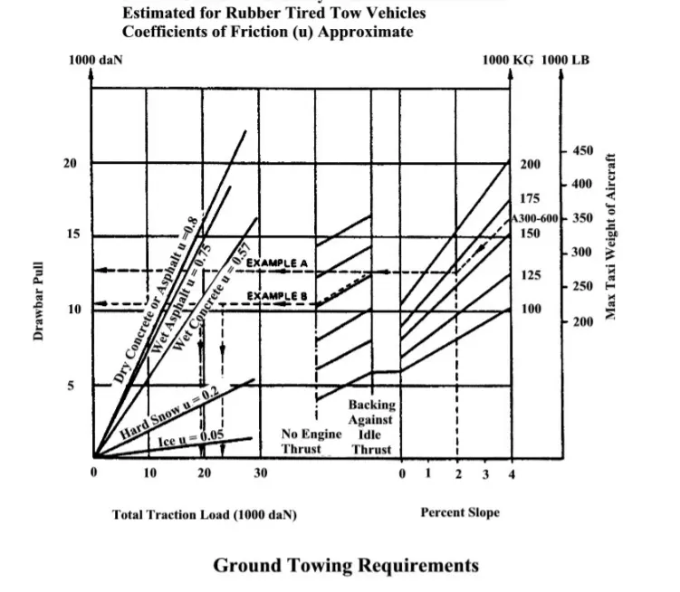
- The tow vehicle is selected from the equipment manufacturer according to tow capability and aircraft model.
- Bliss-Fox Ground Support Equipment, part of the NEPEAN Transport Group, is an Australian company that has been supplying ground support equipment for over 40 years. The Company has developed a suite of tractors including the F1-500 54 – 70 tonne, the F1-300 27 – 45 tonne and the F1-80 9 -12 tonne, as well as a uniquely designed TBLT for the push back, tow, or hanger movements of empty or fully laden commercial aircraft including A300, A310, A330, A340-300/600, B767, B777 B747-400.
- Typically, the F1-500 version is designed for both push back and extended towing of aircraft up to 600 tonnes (A380-800F). Drop-in ballast easily transforms the tractor from a standard 54 tonnes for A340 & B747 up to 70 tonnes for A380-800F with no obstruction to the operators’ line-of-sight. The F1-500 features a 360kW (483 hp) diesel Engine with 1990 Nm (1468 Ft/lbs) of torque.
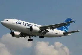
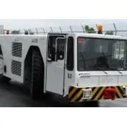
- Airbus 310 F1-500
-
Aircraft weight airbus A310 gvw = 150000Kg / 5 = 30,000Kg 1/5th mass is taken
-
G ,Gear ratio of vehicle= 23:92
-
Dia of tractor wheel 822mm, radius 411mm, 0.4m
-
Drag force of aircraft = `0.5*rho*A*V^2*Cd` = 0.5*1.225*219*2.77^2*0.025 = 25.73 KN
-
Rolling resistance of aircraft = `Urr*m*g` = 0.03*30000*9.81 = 8.83 KN
-
Drag force of tractor = 0.9*rho* A_veh * V_veh ^2*Cd_veh = 0.9*1.225*24*2.27^2*0.025= 2.28KN
-
Rolling resistance of tractor = Urr_veh * M_veh *g = 0.9*8291*9.81 = 73.20KN
-
Total rolling resistance = 82.03 KN
-
Total force = Total rolling resistance + Drag force of aircraft + Drag force of vehicle = 82.03 + 25.73 + 2.28= 110.4
-
Power = Total force * velocity = 110.4 * 2.77 = 305.80 KW
-
T for tractor = F.r/G = 110.4*0.41/0.25 = 181.5 KNm
- A Simulink model is represented considering all forces is represented below:
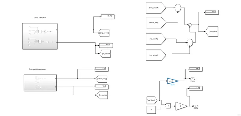
- The subsystems in model are divided into aircraft and towing vehicle.
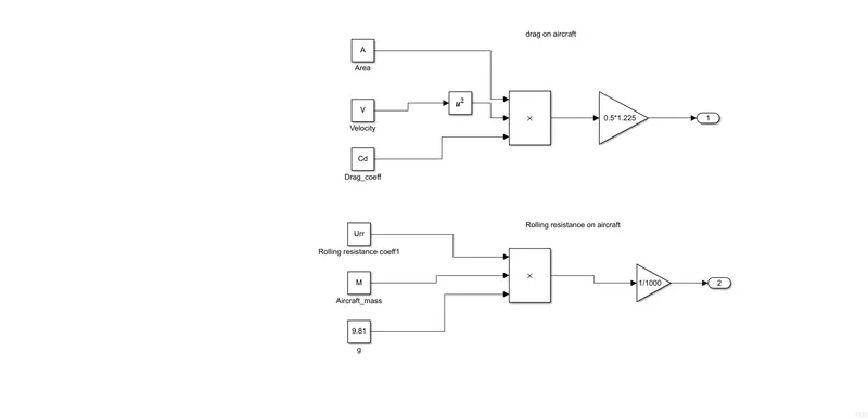
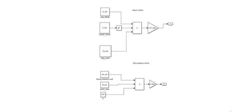
- The variables defined in base workspace is as shown below:
-
A = 219; % aircraft frontal area V = 2.77; % velocity while moving Cd = 0.025; % drag coefficient of aircraft M = 30000; % in kg, 1/5 mass is taken which will be acting on the vehicle as per manual Urr = 0.03; %rolling resistance coef of aircraft Urr_veh = 0.9; M_veh = 8291; % in kg mass of vehicle A_veh = 24; % m^2 area of vehicle Cd_veh= 0.025; % same as aircraft V_veh = 2.77; % m/s velocity of vehicle R = 0.41; % in meters G = 0.25; %planetory gear ratio for higher torque- 23:92 - 7.Design an electric powertrain with type of motor, it’s power rating, and energy requirement to fulfill aircraft towing application. Estimate the duty cycle range to control the aircraft speed from zero to highest. Make all required assumptions. Prepare a table of assumed parameters. Draw a block diagram of powertrain
- Assumptions:
- To towing vehicle is assumed to be electric in nature
- The power requirement to tow the vehcile from simulink simulation was found to be 310 kw
- The battery pack voltage is assumed to be 400v, for single cell voltage is 4V
- The rated power of IC powered tow vehicle is 360 KW
- The same power is assumed at electric power train as well
- Assuming a motor efficiency of 95%
- I=360000/400= 900 A
- a) Motor design
- Torque required=11.33 KNm
- Motor losses=20% , by accommodating this : Net torque required = 11.23+2.26=13.5KNm
- power required to tow vehicle at 2.77 m/s=306 Kw
- motor eff=95%,power after considering efficiency=306+(0.05)*306=321.3Kw
- b) Battery capacity
- The energy of battery required when a tow truck is used for 10 minutes=321*10*60=192600 KJ=53.33kWh
- c) power converter
- A dc-dc converter handling 360KW rated is chosen
- Duty cycle=321/360=0.89
- The duty cycle will be 0 to 0.89 rated power
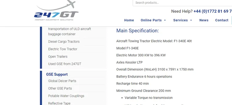
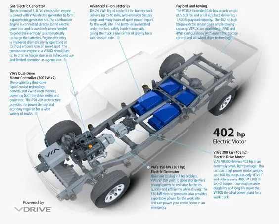
- A typical tow truck motor rating is shown below which aligns with the estimations:
- Drive train of a tow truck
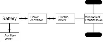
- Block diagram for above designed drive train: Since a DC motor is used the power converter will be DC-DC type
- References
- 1) Airplane weight nomenclature- https://aviation.stackexchange.com
- 2) Major aircraft weights-Weight and Balancehandbook,FAA,https://www.faa.gov/regulations_policies/handbooks_manuals/aviation
- 3) Take of weight of airliners-https://en.wikipedia.org/wiki/List_of_airliners_by_maximum_takeoff_weight
- 4) Understanding speed differences-https://www.grc.nasa.gov/www/k-12/airplane/move.html
- 5) Ground related hazards-http://www.boeing.com/commercial/aeromagazine/aero_06/textonly/s02txt.html
- 6) Need of pushback and push back tractors-https://jalopnik.com/pushback-tugs-are-the-coolest-vehicles-at-the-airport-1655333766
- 7) Aircraft tyres-https://www.scribd.com/document/237343229/Aircraft-Tire-Properties,https://www.aviationpros.com/aircraft/article/10388042/understanding-the-basics-of-aircraft-tire-construction-and-maintenance
- 8) Aircraft take off terminology-https://www.faa.gov/regulations_policies/handbooks_manuals/aviation/airplane_handbook/media/07_afh_ch5.pdf
- 7) selection of tow vehicle-http://nepean.com/transport/products-services/bliss-fox/f1-500-aircraft-tractor
- 8) https://www.wired.com/2016/08/airplane-tires/