Project-1: Powertrain for aircraft in runways
1. Search and list out the total weight of various types of aircrafts
Solution:-
MTOW = Maximum take-off weight, MLW = Maximum landing weight, TOR = Take-off run, LR = Landing run
|
Type |
MTOW [kg] |
MLW [tonnes] |
TOR [m] |
LR [m] |
||
|
640,000 |
591.7 |
3500 |
Heavy |
Super |
||
|
589,670 |
3660 |
Heavy |
Super |
|||
|
575,000 |
394 |
3100 |
1930 |
Super |
Super |
|
|
447,700 |
346.091 |
3100 |
1800 |
Heavy |
Heavy |
|
|
443,613 |
306.175 |
3100 |
Heavy |
Heavy |
||
|
412,770 |
295.742 |
3090 |
Heavy |
Heavy |
||
|
Antonov An-124-100M |
405,060 |
330 |
2520 |
900 |
Heavy |
Heavy |
|
396,900 |
295.742 |
3018 |
2179 |
Heavy |
Heavy |
|
|
381,000 |
288.417 |
2530 |
1494 |
Heavy |
Heavy |
|
|
377,840 |
285.700 |
3338 |
2109 |
Heavy |
Heavy |
|
|
377,840 |
260.320 |
3222 |
1905 |
Heavy |
Heavy |
|
|
371,950 |
240 |
3050 |
2010 |
Heavy |
Heavy |
|
|
367,400 |
256 |
3100 |
2100 |
Heavy |
Heavy |
|
|
347,800 |
260.816 |
2830 |
Heavy |
Heavy |
||
|
351,800 |
251.29 |
3100 |
Heavy |
Heavy |
||
|
347,450 |
223.168 |
3000 |
Heavy |
Heavy |
||
|
340,200 |
265.300 |
Heavy |
Heavy |
|||
|
308,000 |
233.5 |
Heavy |
Heavy |
|||
|
299,370 |
237.683 |
3380 |
Heavy |
Heavy |
||
|
297,550 |
213.00 |
3380 |
1550 |
Heavy |
Heavy |
2. Is there any difference between ground speed and air speed?
Solution:-
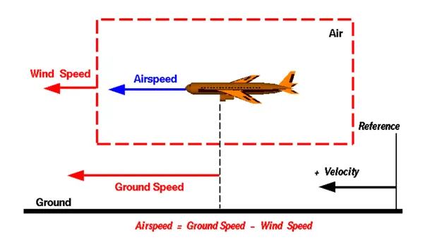
One of the most confusing concepts for young scientists is the relative velocity between objects. Aerodynamic forces are generated by an object moving through a fluid (liquid or gas). A fixed object in a static fluid does not generate aerodynamic forces. Hot air balloons "lift" because of buoyancy forces and some aircraft like the Harrier use thrust to "lift" the vehicle, but these are not examples of aerodynamic lift. To generate lift an object must move through the air, or air must move past the object. Aerodynamic lift depends on the square of the velocity between the object and the air. Now things get confusing because not only can the object be moved through the air, but the air itself can move. To properly define the relative velocity, it is necessary to pick a fixed reference point and measure velocities relative to the fixed point. In this slide, the reference point is fixed to the ground, but it could just as easily be fixed to the aircraft itself. It is important to understand the relationships of wind speed to ground speed and airspeed.
Wind Speed
For a reference point picked on the ground, the air moves relative to the reference point at the wind speed. Notice that the wind speed is a vector quantity and has both a magnitude and a direction. Direction is important. A 20 mph wind from the west is different from a 20 mph wind from the east. The wind has components in all three primary directions (north-south, east-west, and up-down). In this figure, we are considering only velocities along the aircraft's flight path. A positive velocity is defined to be in the direction of the aircraft's motion. We are neglecting cross winds, which occur perpendicular to the flight path but parallel to the ground, and updrafts and downdrafts, which occur perpendicular to the ground.
Ground Speed
For a reference point picked on the ground, the aircraft moves relative to the reference point at the ground speed. Ground speed is also a vector quantity so a comparison of the ground speed to the wind speed must be done according to rules for vector comparisons.
Airspeed
The important quantity in the generation of lift is the relative velocity between the object and the air, which is called the airspeed. Airspeed cannot be directly measured from a ground position, but must be computed from the ground speed and the wind speed. Airspeed is the vector difference between the ground speed and the wind speed.
Airspeed = Ground Speed - Wind Speed
On a perfectly still day, the airspeed is equal to the ground speed. But if the wind is blowing in the same direction that the aircraft is moving, the airspeed will be less than the ground speed.
3. Why is it not recommended to use aircraft engine power to move it on the ground at Airport?
Solution:-
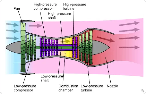
The above image is of an aircraft engine. The first stage is of a Compressor where air pressure increases. In the second stage mixture of air and fuel is done and in the third stage expansion is done through the nozzle which in turn creates the Thrust required to make the aircraft go forward.
To move the aircraft from one place to another, a towing truck is used. We cannot use the aircraft engine to move the aircraft to a small location because the air coming out from the nozzle has a very high speed which in turn can damage the buildings or persons or other aircrafts nearby. Also one of the reason is that there a small gravels present on the ground which when sucked in can damage the compressor blades in the engine. Also there will be unnecessary consumption of fuel. Unwanted noise of the engines which would result in a bad experience of the passengers.
4. How an aircraft is pushed to runway when its ready to take off?
Solution:- A so-called pushback truck reverses the aircraft into taxiing position, pushing it with a towbar attached to the nose-wheel strut. Or, in the most modern versions, by actually lifting the wheel.
Taxiing is the movement of an aircraft on the ground, under its own power, in contrast to towing or pushback where the aircraft is moved by a tug. The aircraft usually moves on wheels, but the term also includes aircraft with skis or floats (for water-based travel). An airplane uses taxiways to taxi from one place on an airport to another; for example, when moving from a hangar to the runway. The term "taxiing" is not used for the accelerating run along a runway prior to takeoff, or the decelerating run immediately after landing, which are called the takeoff roll and landing rollout.
5. Learn about take off power, tyre design, rolling resistance, tyre pressure, brake forces when landing.
Solution:-
- Take off Power:- Take offis the phase of flight in which an aircraft goes through a transition from moving along the ground (taxiing) to flying in the air, usually starting on a runway. Usually the engines are run at full power during take off.
- Tire Design
Designing aircraft tires is a very intense undertaking. Once an aircraft manufacturer goes to the tire manufacturer with the size and weight requirements, the tire manufacturer begins the process of designing a tire that meets the needs of the aircraft manufacturer as well as all regulatory requirements — including foreign regulations in many cases.
Engineers are challenged with designing tires with cool running, heat-resistant materials while simultaneously exceeding tire service requirements. Tire prototypes are put through rigorous tests that simulate cycles of landings, take-offs, and taxi operations. It is only after the tires pass all mandatory tests and meet the requirements of the aircraft manufacturer and airworthiness authorities that the tires are put into production.
Two types of tires are used in aircraft applications — bias-ply tires and radial tires. Although both types of tires share some similarities in design, there are differences that need to be noted.- Bias-ply tire construction
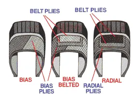
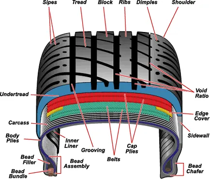
A cutaway of a typical bias-ply tire is shown in Figure 1. Bias-ply tires are popular choices for aircraft tires because of their durability and retreadability. The tire construction consists of the following components:
Tread: The tread is made of rubber mixed with other additives to obtain the desired level of toughness, durability, and resistance to wear. The tread pattern is designed to aircraft operational requirements, with the ribbed tread design used widely due to its good traction under varying runway conditions.
Sidewall: The sidewall is a protective layer of rubber that covers the outer casing ply. It extends from the tread edge to the bead area.
Tread Reinforcing Ply: One or more layers of fabric that strengthens and stabilizes the tread area for high-speed operation. It also serves as a reference for the buffing process when tires are retreaded.
Buff Line Cushion: The buff line cushion is made of rubber compound to enhance the adhesion between the tread reinforcing ply and the breakers or casing plies. It is of sufficient thickness to allow for the removal of the old tread when the tire is retreaded.
Breakers: Breakers are reinforcing plies of rubber-coated fabric placed under the buff line cushion to protect casing plies and strengthen and stabilize the tread area. They are considered an integral part of the casing construction.
Casing Plies: Alternate layers of rubber-coated fabric (running at opposite angles to one another) provide the strength of the tire.
Wire Beads: Hoops of high tensile strength steel wire that anchor the casing plies and provide a firm mounting surface on the wheel. The outer edge of the bead that fits against the wheel flange is called the bead heel. The inner bead edge is called the bead toe.
Apex Strip: A wedge of rubber affixed to the top of the bead bundle.
Flippers: Layers of rubberized fabric that help anchor the bead wires to the casing and improve the durability of the tire.
Ply Turnups: The casing plies are anchored by wrapping them around the wire beads, thus forming the ply turnups.
Chafer: A protective layer of rubber and/or fabric located between the casing plies and wheel to minimize chafing.
Liner: In tubeless tires, the liner is a layer of low permeability rubber that acts as a built-in tube and restricts gas from diffusing into the casing plies. In tube-type tires, a thinner liner is used to prevent tube chafing against the inside ply.
- Radial-ply tire construction
A radial ply tire means the plies of cord are laid out at 90 degrees from the direction of travel, lip to lip, as if the cords radiate out from the imaginary centre of the tire. This type of tire construction is popular for reducing rolling friction of the tire, more breakaway grip, better fuel economy, longer tread life and better steering control.
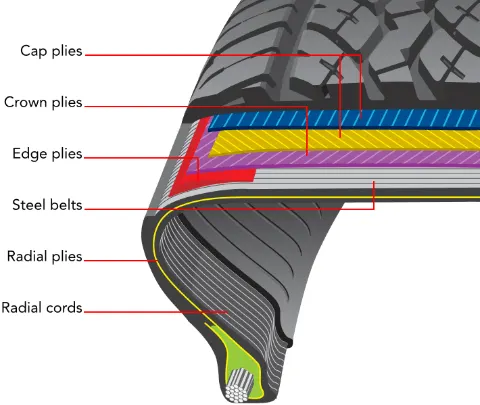
A typical radial tire is illustrated in Figure 2. With their rigid belt, they provide increased landings and reduced rolling resistance. They have fewer components in their construction and are lighter than similarly sized bias ply tires. Components that differ from bias-ply construction as follows:
Overlay: A layer of reinforcing rubber coated fabric placed on top of the belts to aid in high speed operation.
Belt Plies: A composite structure that stiffens the tread area for increased landings. The belt plies increase the tire strength in the tread area.
Casing Plies: As in bias-ply tires, the casing plies are layers of rubber-coated fabric. However, unlike those in bias plies that run at opposite angles to one another, radial plies run radially from bead to bead.
Chippers: The chippers are layers of rubber-coated fabric applied at diagonal angles that improve the durability of the tire in the bead area.
- Rolling resistance
Rolling resistance, sometimes called rolling friction or rolling drag, is the force resisting the motion when a body (such as a ball, tire, or wheel) rolls on a surface. It is mainly caused by non-elastic effects; that is, not all the energy needed for deformation (or movement) of the wheel, roadbed, etc., is recovered when the pressure is removed. Two forms of this are hysteresis losses, and permanent deformation of the object or the surface (e.g. soil). Another cause of rolling resistance lies in the slippage between the wheel and the surface, which dissipates energy. Note that only the last of these effects involves friction, therefore the name "rolling friction" is to an extent a misnomer
The "rolling resistance coefficient" is defined by the following equation:
`F = c_r*N`
where
F is the rolling resistance force
`c_r` is the dimensionless rolling resistance coefficient or coefficient of rolling friction (CRF), and
N is the normal force, the force perpendicular to the surface on which the wheel is rolling.
Below is the table of some values of Rolling coefficients
Coefficient of Rolling friction |
|
|
0.001 - 0.002 |
railroad steel wheels on steel rails |
|
0.001 |
bicycle tire on wooden track |
|
0.002 |
bicycle tire on concrete |
|
0.004 |
bicycle tire on asphalt road |
|
0.008 |
bicycle tire on rough paved road |
|
0.006 - 0.01 |
truck tire on asphalt |
|
0.01 - 0.015 |
car tires on concrete, new asphalt, cobbles small new |
|
0.02 |
car tires on tar or asphalt |
|
0.02 |
car tires on gravel - rolled new |
|
0.03 |
car tires on cobbles - large worn |
|
0.04 - 0.08 |
car tires on solid sand, gravel loose worn, soil medium hard |
|
0.2 - 0.4 |
car tires on loose sand |
- Tyre pressure
An aircraft tire or tyre is designed to withstand extremely heavy loads for short durations. The number of tires required for aircraft increases with the weight of the aircraft, as the weight of the airplane needs to be distributed more evenly. Aircraft tire tread patterns are designed to facilitate stability in high crosswind conditions, to channel water away to prevent hydroplaning, and for braking effect.
Aircraft tires also include fusible plugs (which are assembled on the inside of the wheels), designed to melt at a certain temperature. Tires often overheat if maximum braking is applied during an aborted take off or an emergency landing. The fuses provide a safer failure mode that prevents tire explosions by deflating in a controlled manner, thus minimizing damage to aircraft and objects in the surrounding environment.
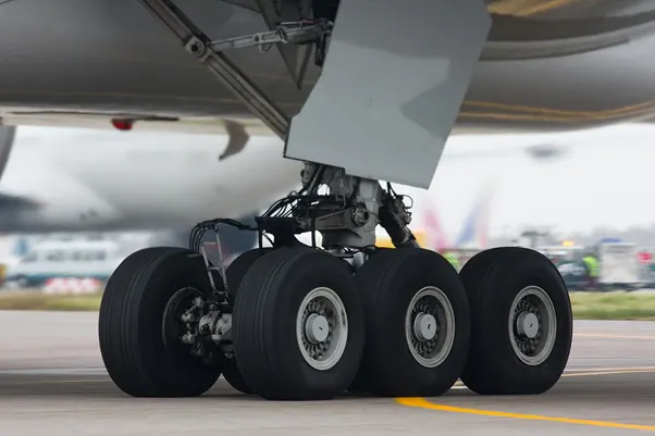
About Tyre Pressure
Each of the twelve Boeing 777-300ER main tires is inflated to 220 psi (15 bar; 1,500 kPa), weighs 120 kg (260 lb), has a diameter of 134 cm (53 in) and is changed every 300 cycles while the brakes are changed every 2000 cycles. Each tire is worth about $5,000. Aircraft tires generally operate at high pressures, up to 200 psi (14 bar; 1,400 kPa) for airliners, and even higher for business jets. The main landing gear on the Concorde was typically inflated to 232 psi (16.0 bar), whilst its tail bumper gear tires were as high as 294 psi (20.3 bar).[4] The high pressure and weight load on the Concorde tyres were a significant factor in the loss of Air France Flight 4590
Tests of airliner aircraft tires have shown that they are able to sustain pressures of maximum 800 psi (55 bar; 5,500 kPa) before bursting. During the tests the tires have to be filled with water, to prevent the test room being blown apart by the energy that would be released by a gas when the tire bursts.
Aircraft tires are usually inflated with nitrogen to minimize expansion and contraction from extreme changes in ambient temperature and pressure experienced during flight. Dry nitrogen expands at the same rate as other dry atmospheric gases (normal air is about 80% nitrogen), but common compressed air sources may contain moisture, which increases the expansion rate with temperature.
The requirement that an inert gas, such as nitrogen, be used instead of air for inflation of tires on certain transport category airplanes was prompted by at least three cases in which the oxygen in air-filled tires had combined with volatile gases given off by a severely overheated tire and exploded upon reaching autoignition temperature. The use of an inert gas for tire inflation eliminates the possibility of tire explosion.
- Brakes
Aircraft braking systems include:
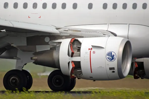
- Aircraft disc Brakesin the landing gear, used to brake the wheels while touching the ground. These brakes are operated hydraulically or pneumatically. In most modern aircraft they are activated by the top section of the rudder pedals ("toe brakes"). In some older aircraft the bottom section is used instead ("heel brakes"). Levers are used in a few aircraft. Most aircraft are capable of differential braking
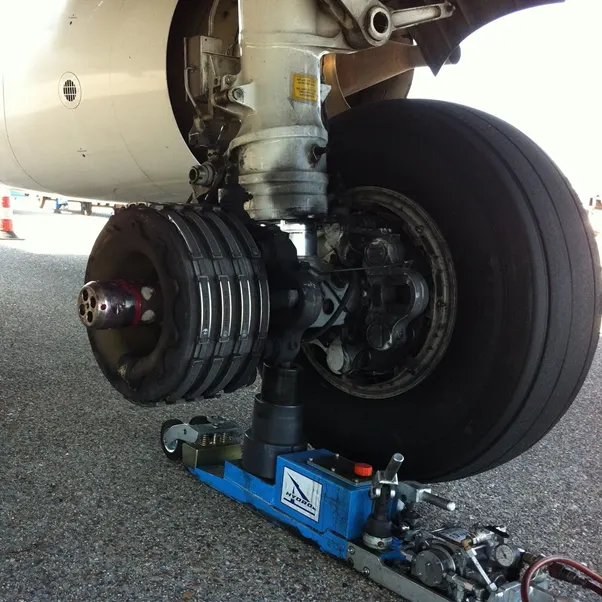
- Thrust reversers, that allow thrust from the engines to be used to slow the aircraft.
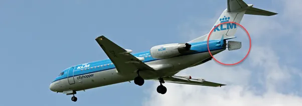
- Air brakes, dedicated flight control surfaces that work by increasing drag.
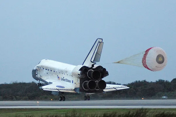
- Large drogue parachutes, used by several former and current military and civilian aircraft and in the Space shuttle
6. With necessary assumptions, calculate the force and power required to push / pull an aircraft by a towing vehicle.
Solution:- We will now calculate the force and hence the power required to tow an Airbus A319
Total gross weight = 68,749 kg
Total weight of Tactor = 54 tonnes = 54,000 kg
`mu_a` = 0.004
`mu_t` = 0.001
Since the towing is not done on a level road, therefore no Hill Climbing Force.
The Motor has to overcome the Rolling Resistance Force as well as Air Drag Force
Which is given by
`F_(r(aircraft)) = mu_a*g*M`
`F_(r(t)) = mu_t*g*m`
Where
`F_(r(aircraft))` is the Rolling Resistance Force on the aircraft
`F_(r(t))` is the Rolling Resistance Force on the towing vehicle
`mu_a` is the coefficient of rolling resistance for aircraft
`mu_t` is the coefficient of rolling resistance for the towing vehicle
M is the total mass of Aircraft
m is the total mass of the towing vehicle
g is the gravitational acceleration
`F_(r(aircraft)) = 0.004*9.81*68749` = 2,697.71 N
`F_(r(t)) = 0.001*9.81*54000`= 529.74 N
Total Rolling Resistance Force = `F_(r(aircraft)) + F_(r(t))` = 3227.45 N = 3.22745 kN
Calculating Air Drag Force
`F_(drag) = ½ * rho * A * V^2 * c_d`
Where
`rho` is the density of Air medium
A is the Frontal area of the Vehicle
V is the velocity of the vehicle
`c_d` is the coefficient of drag
Assumptions
Let the velocity of the towing vehicle = 20 Kmph = 5.55 m/s
Coefficient of drag of the Aircraft = 0.020
Coefficient of drag of the towing vehicle = 0.020
Frontal area of the Aircraft = 25 `m^2`
Frontal area of the Towing vehicle = 40 `m^2`
Density of the Air medium = 1.3
`F_(drag)` = Drag force on Aircraft + Drag Force on Towing vehicle
Drag Force on Aircraft = `0.5*1.3*5.55^2*25*0.02` = 10.01 N
Drag Force on Towing vehicle = `0.5*1.3*40*5.55^2*0.02` = 16.0173 N
`F_(drag)`= 10.01 + 16.0173 = 26.0273 N
Total Force = Total Rolling Resistance Force + Total Air Drag Force
Total Force = 3253.4773 N = 3.2534 kN
For a Safe Design, Assuming 10% increase in Force value
Therefore, Total Force = 3578.82 N = 3.578 kN
Total Power required by the motor = Total Force x Velocity = 19862.451 w = 19.862 kW
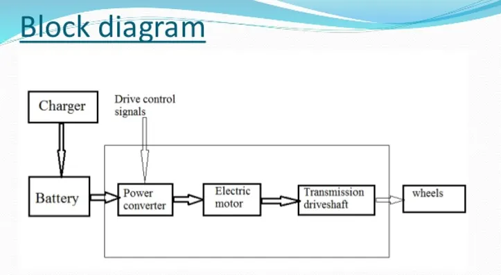
7. Design an electric powertrain with type of motor, it’s power rating, and energy requirement to full fill aircraft towing application. Estimate the duty cycle range to control the aircraft speed from zero to highest. Make all required assumptions. Prepare a table of assumed parameters. Draw a block diagram of powertrain.
Solution:- Assuming the towing application is done for 25 mins i.e 0.416 hrs
Motor Type = BLDC motor
Speed = 3000-5000 rpm
Rated Power = 20 kW
Peak Power = 50 kW
Rated Torque = 75 Nm
Peak Torque = 150 Nm
Input Voltage = 350 V
Input Current = 70 A
Therefore, Input Power = Voltage x Current = 24.5 kW
Energy = Power x time = `24.5*0.416` = 10.192 kJ
Duty cycle = Output power/ Input power = 19.862/24.5 = 0.8106%
Below is the block Diagram for the Towing Application