Project-1: Powertrain for aircraft in runways
1. Search and list out the total weight of various types of aircrafts.
| Aircraft Type | MTOW [kg] |
|---|---|
| Antonov An-225 | 640,000 |
| Scaled Composites Model 351 Stratolaunch | 589,670 |
| Airbus A380-800 | 575,000 |
| Boeing 747-8F | 447,700 |
| Boeing 747-8 | 443,613 |
| Boeing 747-400ER | 412,770 |
| Douglas DC-8-32 | 140,000 |
| Tupolev Tu-154M | 104,000 |
| Bombardier Q400 | 28,000 |
| ATR 42-500 | 18,600 |
| BAe Jetstream 41 | 10,890 |
| Learjet 75 | 9,752 |
| Cessna Citation CJ4 | 7,761 |
MTOW (Maximum Takeoff Weight) is a critical parameter for aircraft as it defines the maximum mass at which an aircraft is certified for takeoff, considering structural and other limitations. These values represent the maximum weights these aircraft can reach during takeoff.
2. Is there any difference between ground speed and air speed?
Ground speed and airspeed are indeed different concepts in aviation, and they are influenced by various factors, including wind. Here's differences between ground speed, airspeed, and wind speed:
Ground Speed: Ground speed is the horizontal speed of an aircraft relative to the ground. It represents how fast an aircraft is moving across the Earth's surface. If an aircraft is hovering vertically without any horizontal motion, its ground speed is zero. Ground speed takes into account both the aircraft's true airspeed and the effect of the wind.
Ground speed can be determined by considering the vector sum of the aircraft's true airspeed and the current wind speed and direction. When there is wind, it affects the ground speed. A headwind (wind blowing against the aircraft's direction of travel) reduces the ground speed, while a tailwind (wind blowing in the same direction as the aircraft's travel) increases it. Additionally, winds blowing at angles to the aircraft's heading have components that can either add to or subtract from the ground speed.
Wind Speed: Wind speed is the speed at which the air is moving in the atmosphere, and it is measured relative to the ground. In aviation, wind speed is a critical factor because it affects an aircraft's performance, especially during takeoff and landing. Wind can blow in various directions and at different speeds, influencing an aircraft's behavior during flight.
Airspeed: Airspeed is the relative velocity between the aircraft and the surrounding air. It is a fundamental parameter in aviation, particularly for generating lift. Airspeed cannot be directly measured from a ground position but must be calculated based on the ground speed and the wind speed. Airspeed represents how fast the air molecules are passing over the aircraft's wings.
The relationship between these parameters can be summarized as follows:
- If there is no wind (i.e., the wind speed is zero), then ground speed equals airspeed.
- When there is a tailwind (wind blowing in the same direction as the aircraft's travel), airspeed is greater than ground speed because the wind adds to the aircraft's speed.
- In the presence of a headwind (wind blowing against the aircraft's direction of travel), airspeed is less than ground speed because the wind subtracts from the aircraft's speed.
- Wind speed is the vector difference between ground speed and airspeed, and it represents the speed and direction of the wind.
It's important for pilots and aviation professionals to consider these differences to ensure safe and efficient flight operations, especially when dealing with varying wind conditions during takeoff, landing, and in-flight maneuvers.
3. Why is it not recommended to use aircraft engine power to move it on the ground at Airport?
Using aircraft engine power to move an aircraft on the ground at an airport is generally not recommended for several reasons:
-
Safety Concerns: The thrust produced by aircraft engines, especially jet engines, can be extremely powerful. This jet blast can create hazardous conditions on the airport apron and taxiways. It has the potential to cause damage to nearby structures, equipment, and even other aircraft. The force generated can be difficult to control, especially during high-power engine running, which could result in a loss of control.
-
Debris Ingestion: Aircraft engines positioned close to the ground while taxiing can also pose a risk of ingesting debris such as sand, stones, or foreign objects. These objects can be blown forward by the engine's exhaust and then sucked into the engine, potentially causing damage to the engine components. This can result in costly maintenance and downtime for the aircraft.
-
Safety of Ground Support Personnel: Ground support personnel, including ramp workers and maintenance crews, often work in close proximity to taxiing aircraft. The powerful jet blast and noise from aircraft engines can pose a risk to their safety. Jet blast can create hazardous wind conditions, and noise levels can be uncomfortable or even harmful to those working on the ground.
-
Visibility: Pushback tugs or vehicles operated by experienced drivers typically have a better view of their surroundings compared to pilots sitting in the cockpit of an aircraft. This improved visibility allows for safer maneuvering on the ground and reduces the risk of accidents or collisions.
-
Fuel Savings: Pushing an aircraft back from the gate and using a tug or pushback vehicle is a more fuel-efficient method compared to using the aircraft's engines. By reducing engine use on the ground, airlines can save on fuel costs and reduce their environmental impact.
-
Noise Pollution: Aircraft engines, particularly at high power settings, can generate significant noise pollution. Multiple aircraft taxiing with their engines running can create a noisy and unpleasant environment for passengers, airport personnel, and nearby residents.
In summary, using aircraft engine power to move an aircraft on the ground is generally discouraged due to safety concerns, potential damage to aircraft and infrastructure, risks to ground support personnel, and the more efficient and environmentally friendly alternative of using pushback vehicles. These considerations prioritize safety, operational efficiency, and environmental responsibility at airports.
4. How an aircraft is pushed to runway when its ready to take off?
When an aircraft is ready to take off, it undergoes a process known as "taxiing" to move from its parking position to the runway. Taxiing involves the aircraft moving on the ground under its own power, in contrast to being towed or pushed by a tug. Here's an elaboration of how taxiing works:
Taxiing: Taxiing is the controlled movement of an aircraft on the ground using its own engines and wheels or landing gear. It is an essential phase of an aircraft's operation at an airport and involves several steps:
-
Preparation: Before taxiing, the flight crew performs pre-flight checks and preparations, ensuring that the aircraft's systems are functioning correctly and receiving clearance from air traffic control (ATC) for departure.
-
Pushback (if necessary): In many cases, especially at commercial airports, aircraft are parked at gates or parking stands close to terminal buildings. To move away from the gate, aircraft often require assistance from a pushback tug or vehicle. Ground crew personnel connect the tug to the aircraft's nose gear and guide it away from the gate.
-
Engine Start: Once the aircraft is in a suitable position away from the gate or parking stand, the flight crew starts the aircraft's engines. Aircraft typically have two or more engines, and they provide the necessary power for taxiing.
-
Taxi Route: With the engines running, the aircraft begins to taxi under its own power. The flight crew uses the aircraft's throttle, brakes, and steering systems to control its movement on the ground. The aircraft follows designated taxiways, which are like "roads" on the airport, to reach the runway.
-
ATC Communications: Throughout the taxiing process, the flight crew maintains communication with air traffic control (ATC). ATC provides instructions and clearances, guiding the aircraft's taxi route to ensure safe separation from other aircraft on the ground.
-
Holding Points: Along the taxi route, there may be designated holding points where the aircraft must stop and await further instructions from ATC. These holding points are often located near runway entrances to ensure safe sequencing of departures.
-
Runway Entry: Upon reaching the designated runway for departure, the aircraft stops at the runway holding point. Here, the flight crew receives final clearance from ATC to enter the runway and proceed with the takeoff.
-
Takeoff: Following clearance, the flight crew advances the throttle to increase engine power, initiating the takeoff roll. The aircraft accelerates down the runway until it reaches the required takeoff speed (Vr) and becomes airborne.
-
Climb and Departure: After takeoff, the aircraft climbs to its designated cruising altitude and follows its flight plan for the journey to its destination.
It's important to highlight that the entire taxiing process is conducted under the control of the flight crew, who follow specific procedures and maintain communication with ATC to ensure the safe and orderly movement of the aircraft on the ground. Pushback tugs or vehicles are employed to maneuver the aircraft in and out of parking positions, particularly at busy airports, to facilitate taxiing to the runway for takeoff.
5. Learn about take off power, tyre design, rolling resistance, tyre pressure, brake forces when landing.
Take off power:
Take off power can be predicted using a simple measure of the acceleration of the aircraft along the runway based on force equilibrium.
The forces involved will be.
T is Thrust of propulsion system pushing aircraft along the runway.
D is Aerodynamic Drag of vehicle resisting the aircraft motion.
F is Rolling resistance friction due to the contact of wheels or skids on the ground.
During the take-off run, the imbalance in these forces will produce an acceleration along the runway.
m*(dv/dt)=T-D-F
where, dv/dt is the acceleration along the runway and m is the mass of the vehicle.
The procedure for take-off will be that the vehicle will accelerate until it reaches a safe initial flying speed. The pilot can then rotate the vehicle to an attitude to produce a climb lift and it will ascend from the ground. The determination of this safe flying speed or rotation speed. V, is a critical factor in determining take-off performance. Take-off rules vary slightly depending on the aircraft category.
For Small commuter aircraft
V= 1.1*VSTALL
or
V=1.05*V Control
VSTALL≡W0.5ClmaxρS">VSTALL≡√W0.5Clmaxρ
where S-Runway length
Take Off power = force*displacement
(m⋅dvdt)⋅2⋅S1⇒(T-D-F).S1">(m⋅dvdt)⋅2⋅S1⇒(T−D−F).S1
Tyre Design:
Designing aircraft tires is a very intense undertaking The tyre is designed to withstand heavy loads while landing, take off, taxing, and parking. The number of wheels required for aircraft increases with the weight of the aircraft, as the weight of the aeroplane needs to be distributed more evenly. Aircraft tyre generates more heat during landing Aircraft drags the wheel until they match the rotational velocity of wheels. Due to this heat generates. Aircraft's tread pattern is designed to facilitate stability in high crosswind conditions, to channel water away to prevent hydroplaning and for braking effect.
Construction of tyre:
Radial Tyre: It has fibre strands of the ply fabric oriented at 90° to the direction of rotation and the tyre sidewall. This restricts flexibility bidirectional and the flexibility of the sidewall while it strengthens the tyre to carry heavy loads. Due to their unique construction most radial tyres are resistant to penetration ad cuts. Due to stiffer tread they distribute weight evenly. Thus provide greater traction. Radial tyres have an advantage in term of reducing the heat better.
Bias-ply Tyre: It has the fabric bias oriented with and across the direction of rotation and the sidewall. Since fabric can stretchon the bias, the tyre is flexible and can absorb loads. Tyre strength is obtained by adding plies. It is cut resistant is sidewall area. These tyres do not offer as much smoothness in terms of riding quality.
Rolling Resistance:
Rolling resistance is the force resisting the motion when a body (such as ball, tyre or wheel) rolls on a surface. Rolling resistance can be seen in the aircraft when the aircraft takes-off from the runway & while landing at the runway with the help of their wheels.
Rolling resistance can be expressed as Frr=μrr⋅m⋅g">Frr=μrr⋅m⋅g(N).
Where
Frr">Frr is the Rolli resistance(N)
μrr">μrr is coefficient of rolling resistance.
m is mass (kg)
g is acceleration due to gravity = 9.81m/s^2
Tyre pressure:
Aircraft tyres operate at such high extremes of pressure, load, and speed, their care and service is critically important. The most important action an operator can take to prevent tyre-related events is to maintain proper tire inflation pressure. Failure to keep aircraft tires properly inflated can lead to very serious consequences. One relatively easy way to help avoid those consequences is to check tire pressures regularly and service them as necessary. Following these three actions is a good way to make sure you get the most value out of your tires and contribute to the safe operation of your aircraft.
Aircraft tires are usually inflated with nitrogen to minimize expansion and contraction from extreme changes in ambient temperature and pressure experienced during flight. Dry nitrogen expands at the same rate as other dry atmospheric gases (normal air is about 80% nitrogen). but common compressed air sources may contain moisture, which increases the expansion rate with temperature.
Also, the use of an inert gas for tire inflation eliminates the possibility of tire explosion.
Relation to Rolling Resistance and Tire Pressure:
Rolling resistance and Tire pressure are inversly proportional.
Braking Forces During Landing:
Following braking devices are used to decelerate the aircraft -
1. Spoilers.
2. Wheel Brakes (Including Anti-Skid systems & Auto-Brake systems).
3. Reverse Thrust
Spoilers:
The mechanical deflection of parts of the wing upper surface by increasing aerodynamic drag on the moving aircraft. This can be achieved by raising upper wing surface panels called ground spoilers or by operation of a tail cone 'clamshell' type air brake and also by increasing the effective downward load on the landing gear and thereby increasing the efficiency of wheel braking
Wheel Brakes:
To be effective, braking action at any speed depends upon sufficient friction existing between the tires and the runway surface achieved through freely rotating wheels.
Anti skid system:
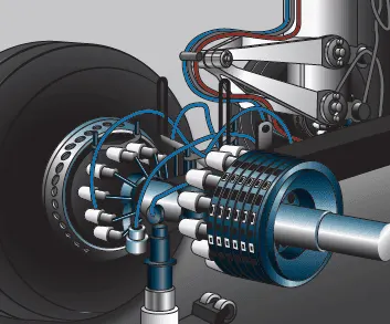
When landing on slippery runways, there's a chance that the wheels may start to skid as the brakes are applied. To stop this from happening and to maintain maximum effective braking, each wheel has anti-skid protection.
Using a variety of sources to determine the aircraft speed, the brake units know how fast the wheels should be spinning. If that speed drops significantly, it's because the current brake pressure on that wheel is too great and the wheel is just skidding over the surface.
In this situation, the anti-skid system automatically reduces the braking on that wheel to a point where the skid stops before reapplying the pressure.
Reverse Thrust:
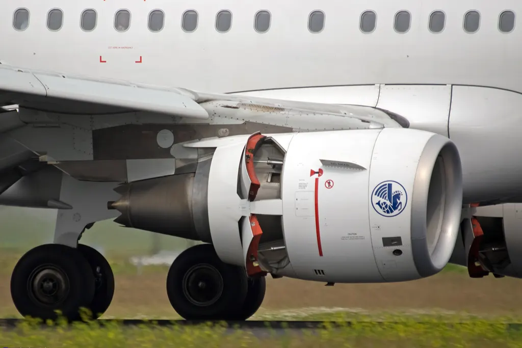
Thrust reversers provide a deceleration force that is independent of runway condition. Thrust reverser efficiency is higher at high airspeed therefore. Treversers must be selected as early as possible after touchdown.
Thrust reversers should be returned after reverse idle at low airspeed to prevent engine stall or foreign object damage.
#6. A. With necessary assumptions, calculate the force and power required to push / pull an aircraft by a towing vehicle.
B. Develop the model for the calculated force and power using Simulink.
A. With necessary assumptions, calculate the force and power required to push / pull an aircraft by a towing vehicle.
Considering:
Total mass of ther aircraft (including payload) for airbus a380 = 575,000kg.
Mass of the push back: 1000kg (assumed)
Rolling Resistance (Frr):
Coefficient of rolling resistance (Crr) = 0.002 (on tarmac)
Rolling resistance force is given by Frr=Crr⋅m⋅g">Frr=Crr⋅m⋅g
For the aircraft: Frr=0.002⋅575000⋅9.81⇒Frr=11281.5N⇒Frr=11.2815kN">Frr=0.002⋅575000⋅9.81⇒Frr=11281.5N⇒Frr=11.2815kN=0.002⋅575000⋅9.81⇒=11281.5⇒=11.2815For the Towing Vehicle: Frrt=0.002⋅1000⋅9.81⇒Frrt=19.62N">Frrt=0.002⋅1000⋅9.81⇒Frrt=19.62N=0.002⋅1000⋅9.81⇒=19.62
As the towing vehicle resistance is so less compared to the Aircraft because this is a heavy aircraft these can be neglected
Aerodynamic resistnace (Far):
Drag coeffcient(Cd): 0.025
Air Density (ρ">ρ) = 1.125kg/m^3
Frontal Area (A): 150m^2.
Velocity (v) = 14.5kmph or 4m/s
Far=12⋅Cd⋅ρ⋅A⋅v2">Far=12⋅Cd⋅ρ⋅A⋅v2=
Far=12⋅0.025⋅1.125⋅150⋅42⇒33.75N">Far=12⋅0.025⋅1.125⋅150⋅42⇒33.75N
As the vehicle and Plane is moving at very low speed Aerodynamic resistance can be neglected
Hill Climb Resistnace:
Runways are constructed flat so Gradient resistance/ hill climb force is neglected.
Total Resistance:
Ft=11.2815kN">Ft=11.2815kN=11.2815
Power Required:
P=Ft⋅v⇒P=11.2815⋅4⇒45.26kW">P=Ft⋅v⇒P=11.2815⋅4⇒45.26kW
The min power required by the tow vehicle is 45.26kW to taxi a heavy air craft at 4m/s.
B. Develop the model for the calculated force and power using Simulink.
Simulink Model:
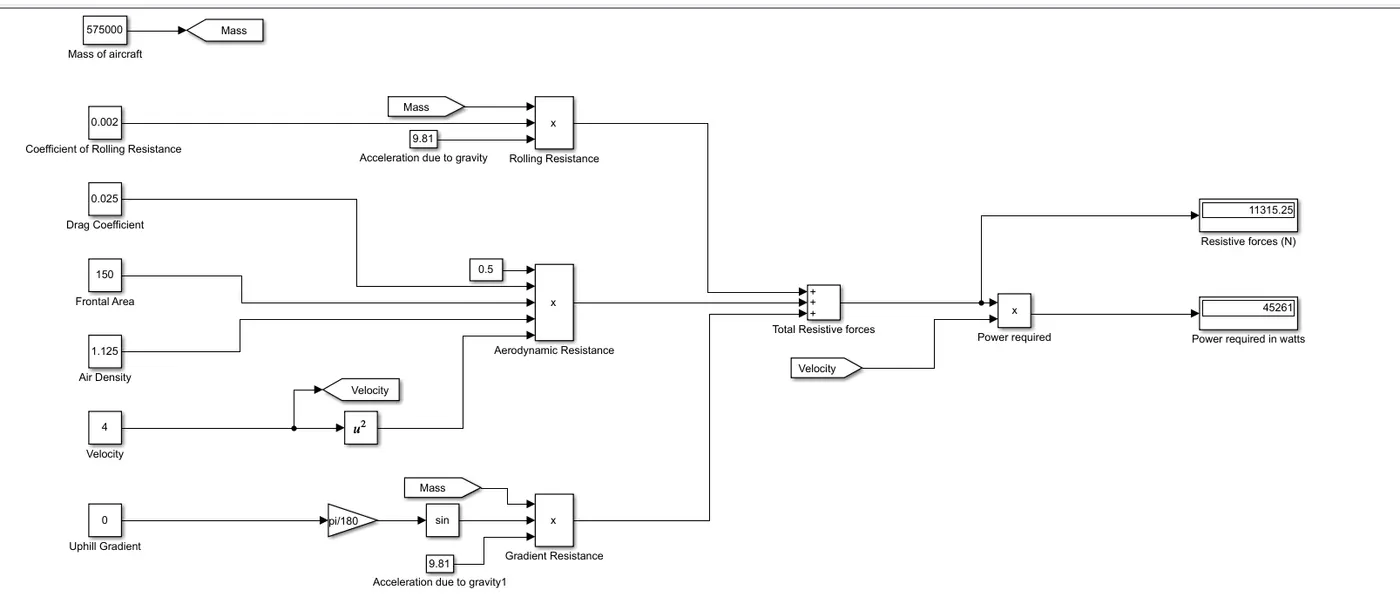
- constant blocks are used to feed the parameters such as mass, coefficients and other parameters
- using product block the resistive forces are calculated.
- using sum block, total resistive forces can be calculated.
- the outputs are visualised using display blocks.
7.
A. Design an electric powertrain with type of motor, it’s power rating, and energy requirement to fulfill aircraft towing application in Simulink. Estimate the duty cycle range to control the aircraft speed from zero to highest. Make all required assumptions. Prepare a table of assumed parameters. Draw a block diagram of powertrain.
Estimation of Duty Cycle:
Based on the calculation done in study 6
The Power Required for towing of the aircraft is 45.26kW.
Motor Considred for the drive train is REB 90
Technical Data:
| Type | Voltage | Continuous / Peak power | Working rotation | Max torque | Weight | Cooling |
| REB 90 | 400–800 V | 60–70 kW / 80 kW | 1 500–4 000 rpm | 300 Nm | 22 000 g |
Air / Hybrid (air + fluid) |
Considering 60kW as continuous power, so the voltage will be 400V
Battery power is considred to be 550v
Duty cycle is given by VoVb">VoVb
where Vo is motor required voltage
Vb is battery voltage.
d=400550⇒0.7272">d=400550⇒0.7272
As there will be losses due to the resistance of FET and Inductance.
Correction factor is considred to be 90%
As there is 10% loss, the voltafge demanded by the motor should be 10% more than required
d=0.7272⋅(1+0.1)=0.799≈0.8">d=0.7272⋅(1+0.1)=0.799≈0.8
so the voltage demand should be around 440V from the battery.
| Assumed Parameters | ||
| Mass of aircraft | 575000 | kg |
| Mass of the push back truck | 1000 | kg |
| Coefficient of Rolling Resistance | 0.002 | |
| Drag Coefficient | 0.025 | |
| Air density | 1.125 | kg/m^3 |
| Frontal Area | 150 | m^2 |
| Velocity | 4 | m/s |
| Uphill gradient | 0 | deg |
| Battery Voltage | 550 | V |
| Correction Factor | 0.8 | |
Block Diagram:
Simulink Model:
Input:
Output:
From the motor:
From the Battery:
B. Also, Design the parameters in excel sheet.
attached