Project-1: Powertrain for aircraft in runways
PART [A-1]: List of the total weight of various types of aircrafts
The aircraft gross weight is the total aircraft weight at any moment during the flight or ground operation.Gross weight will decrease during a flight due to fuel and oil consumption & It may also vary during a flight due to payload dropping or in-flight refuelling.
At the moment of releasing its brakes, the gross weight of an aircraft is equal to its takeoff weight. During flight, an aircraft's gross weight is referred to as the en-route weight or in-flight weight.
The different terms represent different weights or masses1. For each flight, the weights are taken into account for several reasons.A brief description about these is below:
1.Manufacturer's empty weight (MEW)
Also called Manufacturer's Weight Empty (MWE) or Licensed Empty Weight
It is the weight of the aircraft "as built" and includes the weight of the structure, power plant, furnishings, installations, systems and other equipment that are considered an integral part of an aircraft.This excludes any baggage, passengers, or usable fuel.
2.Zero-fuel weight (ZFW)
This is the total weight of the airplane and all its contents (including unusable fuel), but excluding the total weight of the usable fuel on board.As a flight progresses and fuel is consumed, the total weight of the airplane reduces, but the ZFW remains constant.Maximum zero fuel weight (MZFW) is the maximum weight allowed before usable fuel and other specified usable agents (engine injection fluid, and other consumable propulsion agents) are loaded.
3.Operating empty weight (OEW) (Roughly equivalent to basic empty weight on light aircraft)
It is the basic weight of an aircraft including the crew, all fluids necessary for operation such as engine oil, engine coolant, water, unusable fuel and all operator items and equipment required for flight but excluding usable fuel and the payload.
4.Payload:-It is the carrying capacity of an aircraft. It includes cargo, people, extra fuel. In the case of a commercial airliner, it may refer only to revenue-generating cargo or paying passengers.
5.Maximum takeoff weight (MTOW):-This is the maximum weight at which the pilot of the aircraft is allowed to attempt to take off3.
6.Regulated takeoff weight (RTOW):-Depending on different factors (e.g. flap setting, altitude, air temperature, length of runway), RTOW or maximum permissible takeoff weight varies for each takeoff. It can never be higher than MTOW.
7.Maximum landing weight (MLW):-This maximum weight at which an aircraft is permitted to land3.The following image depicts takeoff weight components
8.Maximum ramp weight (MRW):-It also called maximum taxi weight (MTW).It is the maximum weight authorized for maneuvering (taxiing or towing) an aircraft on the ground.
9.Aircraft gross weight:-It is the total aircraft weight at any moment during the flight or ground operation. This decreases during flight due to fuel and oil consumption.
List of the total weight of various types of aircrafts
| Aircraft | Empty Weight | Max Fuel Weight | Max Cargo Weight | Max Gross Takeoff Weight |
|---|---|---|---|---|
| Antanov AN-225 | 628,000 lbs 285,000 kg |
661,400 lbs 300,000 kg |
417,000 lbs 190,000 kg |
1,411,000 lbs 640,000 kg |
| Airbus A380-800 | 611,000 lbs 277,000 kg |
560,000 lbs 254,000 kg |
185,000 lbs 84,000 kg |
1,268,000 lbs 575,000 kg |
| Boeing 747-800 | 485,300 lbs 220,100 kg |
427,400 lbs 194,000 kg |
295,000 lbs 134,000 kg |
987,000 lbs 447,700 kg |
| Airbus A340-500 | 370,000 lbs 168,000 kg |
386,300 lbs 175,000 kg |
119,000 lbs 54,000 kg |
820,000 lbs 372,000 kg |
| Boeing 777-300ER | 370,000 lbs 168,000 kg | 320,800 lbs 145,500 kg | 148,000 lbs 67,100 kg |
776,000 lbs 352,000 kg |
| Boeing 787-10 | 299,000 lbs 135,500 kg | 223,500 lbs 101,500 kg |
126,300 lbs 57,300 kg | 560,000 lbs 254,000 kg |
| Boeing 737-900 | 98,500 lbs 44,700 kg |
53,100 lbs 24,000 kg |
44,600 lbs 20,200 kg |
187,000 lbs 85,000 kg |
| Airbus A320-100 | 93,900 lbs 42,600 kg |
48,700 lbs 22,100 kg |
44,000 lbs 20,000 kg |
150,000 lbs 68,000 kg |
| Embraer 190 | 63,500 lbs 28,800 kg |
28,600 lbs 13,000 kg |
28,800 lbs 13,100 kg |
106,000 lbs 48,000 kg |
| Gulfstream G650 | 54,000 lbs 24,500 kg | 48,200 lbs 21,900 kg | 6,500 lbs 3,000 kg |
100,000 lbs 45,200 kg |
| Bombardier CRJ900 | 48,160 lbs 21,850 kg | 19,600 lbs 8,900 kg | 6,075 lbs 2,760 kg | 80,500 lbs 36,500 kg |
| Bombardier Q400 | 39,300 lbs 17,800 kg |
11,700 lbs 5,300 kg |
18,700 lbs 8,500 kg |
62,000 lbs 28,000 kg |
| Learjet 75 | 13,900 lbs 6,300 kg | 6,060 lbs 2,750 kg |
2,900 lbs 1,300 kg |
21,500 lbs 9,700 kg |
| Cessna Citation CJ4 | 10,300 lbs 4,700 kg | 5,800 lbs 2,650 kg |
2,200 lbs 1,000 kg | 17,200 lbs 7,800 kg |
| Beechcraft King Air B100 | 7,100 lbs 3,200 kg | 3,200 lbs 1,450 kg |
4,150 lbs 1,900 kg |
12,000 lbs 5,400 kg |
| Diamond DA50 RG | 3,200 lbs 1,450 kg |
340 lbs 155 lbs |
1,250 lbs 560 kg |
4,400 lbs 2,000 kg |
| Beechcraft Bonanza G36 | 2,500 lbs 1,150 kg | 450 lbs 200 kg |
850 lbs 385 kg |
3,660 lbs 1,660 kg |
| Cessna 206H | 2,200 lbs 990 kg |
520 lbs 235 kg |
1,150 lbs 520 kg |
3,600 lbs 1,630 kg |
| Sirrus SR22 | 2,250 lbs 1,000 kg | 485 lbs 220 kg |
950 lbs 430 kg |
3,600 lbs 1,630 kg |
| Cessna 172R | 1,700 lbs 770 kg |
380 lbs 170 kg |
560 lbs 255 kg |
2,425 lbs 1,100 kg |
PART [A-2]: Is there any difference between ground speed and air speed?
SOLUTION:Yes there is difference between ground speed and air speed which are explained below,
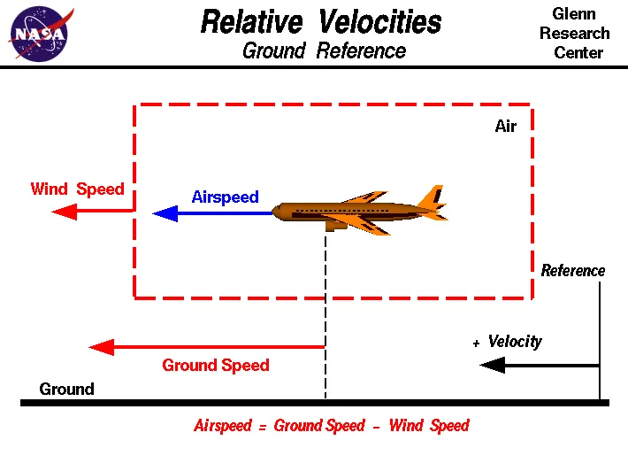
Wind Speed
For a reference point picked on the ground, the air moves relative to the reference point at the wind speed. Notice that the wind speed is a vector quantity and has both a magnitude and a direction. Direction is important. A 20 mph wind from the west is different from a 20 mph wind from the east. The wind has components in all three primary directions (north-south, east-west, and up-down). In this figure, we are considering only velocities along the aircraft's flight path. A positive velocity is defined to be in the direction of the aircraft's motion. We are neglecting cross winds, which occur perpendicular to the flight path but parallel to the ground, and updrafts and downdrafts, which occur perpendicular to the ground.
Ground Speed
For a reference point picked on the ground, the aircraft moves relative to the reference point at the ground speed. Ground speed is also a vector quantity so a comparison of the ground speed to the wind speed must be done according to rules for vector comparisons.
Airspeed
The important quantity in the generation of lift is the relative velocity between the object and the air, which is called the airspeed. Airspeed cannot be directly measured from a ground position, but must be computed from the ground speed and the wind speed. Airspeed is the vector difference between the ground speed and the wind speed.
Airspeed = Ground Speed - Wind Speed
On a perfectly still day, the airspeed is equal to the ground speed. But if the wind is blowing in the same direction that the aircraft is moving, the airspeed will be less than the ground speed.
PART [A-3]:Why is it not recommended to use aircraft engine power to move it on the ground at Airport?
SOLUTION:
Aircraft towing equipment is typically used for the towing and pushback process to avoid some of the significant hazards posed by aircraft engines. When an aircraft's engine is activated, the thrust can create a high-speed wind that can easily cause damage to the airport terminal, surrounding ground vehicles, jetway, baggage and most importantly, ground personnel.
Suppressing the use of engines is especially important when towing a large aircraft, as their more powerful thrust capabilities can become exceedingly dangerous. Engine thrust can easily send any loose items airborne, turn the tiniest grains of dust into hazardous projectiles and create debris that can cause damage to multi-million dollar engines. Additionally, aircraft engines consume a great deal of fuel and generate extreme noise that can be harmful to ground personnel. Using a pushback tug for aircraft is simply a more economical and safer option than running the engines.
Towing and pushback tugs for aircraft are also used to make general maintenance easier for ground personnel.
Another common reason aircraft towing equipment is used in airports concerns aircraft safety from the taxiway to the tow-in gate. Aircraft towing from the taxiway occurs with significant time constraints, so pilots and ground personnel are under extreme pressure to navigate the aircraft quickly and efficiently. The tight confines of the terminal tow-in gate combined with the restricted view of the pilots generally always require a tow in order to arrive safely and on time.
It is easier for truck driver to see the surroundings better than the pilot sitting in the cockpit with limited window. The pushback driver knows the airport better than the pilot.
It also saves fuel. virgin Atlantic had proposed a new system in which pushback truck will move the aircraft all the way to runway to save fuel and reduce impact of environment.
The plane engines are very loud. When more than one plane will add up their sound, then it will not be pleasant for passengers and others near airport.
PART [A-5]:How an aircraft is pushed to runway when its ready to take off?
SOLUTION :
pushback
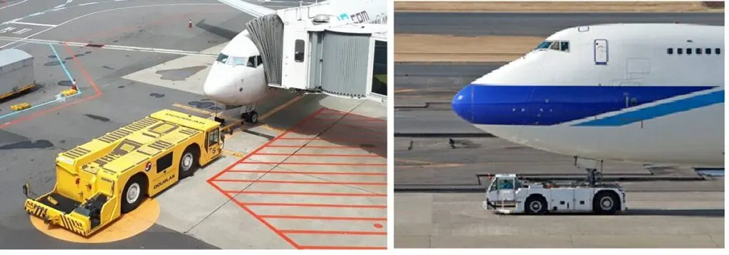
As the name implies, when an aircraft is parked in a nose-in parking position, it should be moved to a position where it can move forward with the help of its own engines. This specific movement is done by pushing the aircraft backward, naming the procedure pushback.
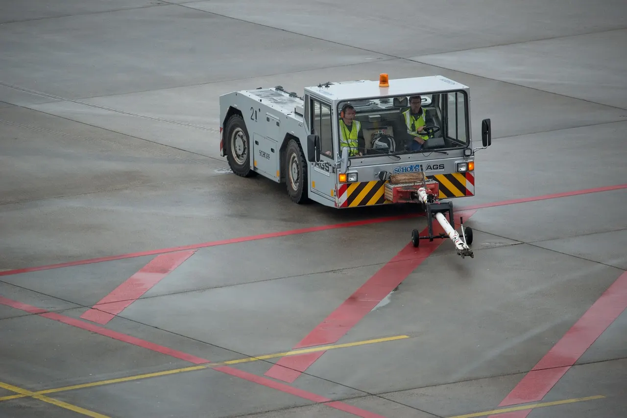
A powerful ground vehicle named tow tug undertakes the pushback via a tow bar attachment to the aircraft nose landing gear. This is more like towing a broken car, but in the opposite direction.
In a typical pushback from the gate for departure, three ground crew members are involved:
- Tow tug drivers
- Aircraft mechanics, who communicate with the cockpit via an interphone
- Auxiliary ground crew members, who carry a fire extinguisher and wheel chocks
Main steps of a pushback
While pushing back airplane sounds quite straightforward, there are a number of steps involved in the procedure. Not only does it involve a ground crew supervisor but also aircraft mechanics and pilots. So, let’s take a look at the 10 crucial steps of a push back:
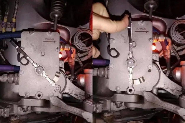
- Once the aircraft is ready for the departure, ground crew (usually the aircraft mechanic) disconnects nose wheel steering (NWS) by moving the steering bypass lever in the steering deactivation box to deactivated position and inserting the bypass pin.
- Connect the bar to the tow fitting in the nose gear.
- Then connect the tow tug with the towing bar.
- Remove the external power unit and all the other attachments to the aircraft including the aerobridge/boarding steps.
- Ground crew communicates with the pilot and informs when the aircraft is ready for the pushback.
- When the pilots grant clearance and release parking brakes, the ground crew personnel at the intercom signals the tow tug driver to commence pushback.
- During the pushback, ground personnel maintains communication with the cockpit and grant clearance for starting aircraft engines.
- When the aircraft reaches desired position, ground personnel inform the pilots that the pushback has been completed and it is time to apply parking brakes.
- When the brakes are applied, tow tug and tow bar are disconnected from the aircraft and taken back.
- The mechanic removes bypass pin and walks away. The mechanic signals the pilots that the bypass pin has been removed. Then the aircraft can move forward with its own power.
PART[A-5]: Learn about take off power, tyre design, rolling resistance, tyre pressure, brake forces when landing.
SOLUTION :
1.Take off power
On take-off, in order to position the aircraft to a safe height away from terrain and obstacles (i.e. a flight path of maximum height and minimum ground distance desired), the engine thrust is set to a high ‘take-off power’ setting (although this is not necessarily full power) and the aircraft attitude is pitched up to maintain a specific speed (usually in the region of V2 + 15kts). Once the ‘safe height’ is reached the engine thrust can therefore be reduced to a more appropriate (i.e. efficient) setting and the aircraft flight path can be changed to a more appropriate (i.e. efficient) flight path.
In order to achieve that described above and also to provide minimum noise disturbance to the area surrounding the airport, regulatory procedures require aircraft to fly one of the two profiles given below during every departure. The aerodrome briefing pages will state which one of the two profiles is to be flown at each particular airport:
- At 1,500ft aal reduce thrust to climb power and accelerate the aircraft towards 250 knots, retracting flaps and slats.
- At 1,500ft aal reduce thrust to climb power maintaining V2 + 15kts. At 3,000ft accelerate the aircraft.
Operator’s SOPs must therefore enable the above procedures to be flown and, as such, controllers will witness flight crews performing certain actions and verbal SOP callouts during the initial climb in order to accomplish this. Aircraft that have highly automated systems will perform the thrust reduction and acceleration manoeuvre with minimal input from the flight crew.
2.Tyre design
When it comes to safety, tyres are one of the most important components of aircraft. They help to absorb the shock of landing and provide cushioning. It also provides the necessary traction for braking and stopping of an aircraft.
An aircraft tyre is designed to withstand extremely heavy loads while landing, take off, taxing, and parking. The number of wheels required for aircraft increases with the weight of the aircraft, as the weight of the aeroplane needs to be distributed more evenly.
Design and construction of Aircrafts tyre
Carcass plies are used to form the tire. They are sometimes called casing plies. An aircraft tyre is constructed for the purpose it serves.
- They support the weight of an aircraft while it is on the ground.
- It also provides the necessary traction for braking and stopping of an aeroplane.
- Tyre also helps to absorb the shock of landing and provide cushioning the roughness of takeoff, roll-out, and taxi operations.
Unlike an automobile or truck tyre, it does not have to carry a load for a long period of continuous operation. However, an aircraft tyre absorbs the high impact loads of landing, and also it’s operating at high speeds for a short time when required.
TYRE CONSTRUCTION
Retreading – Retreading is methods of restoring a worn tyre by renewing the tread area or by renewing the tread area plus one or both sidewalls. Repairs are included in the tyre retreading process.
Load Rating – Load rating is the maximum permissible load at a specified inflation pressure.
Ply Rating – Ply Rating is used to identify the maximum recommended load rating and inflation pressure for a specified tyre. It is an index of tyre strength.
Speed Rating – The speed rating is the maximum takeoff speed to which the tyre has been tested
Skid Depth – Skid depth is the distance between the tread surface and the deepest groove as measured in the mould.
Tread: The tread is made of rubber mixed with other additives to obtain the desired level of toughness, durability, and resistance to wear. The tread pattern is designed to aircraft operational requirements, with the ribbed tread design used widely due to its good traction under varying runway conditions.
Sidewall: The sidewall is a protective layer of rubber that covers the outer casing ply. It extends from the tread edge to the bead area.
Tread Reinforcing Ply: One or more layers of fabric that strengthens and stabilizes the tread area for high-speed operation. It also serves as a reference for the buffing process when tires are retreated.
Buff Line Cushion: The buff line cushion is made of rubber compound to enhance the adhesion between the tread reinforcing ply and the breakers or casing plies. It is of sufficient thickness to allow for the removal of the old tread when the tire is retreated.
Breakers: Breakers are reinforcing plies of rubber-coated fabric placed under the buff line cushion to protect casing plies and strengthen and stabilize the tread area. They are considered an integral part of the casing construction.
Caring Plies: Alternate layers of rubber-coated fabric (running at opposite angles to one another) provide the strength of the tire.
Wire Beads: Hoops of high tensile strength steel wire that anchor the casing plies and provide a firm mounting surface on the wheel. The outer edge of the bead that fits against the wheel flange is called the bead heel. The inner bead edge is called the bead toe.
Apex Strip: A wedge of rubber affixed to the top of the bead bundle.
Flippers: Layers of rubberized fabric that help anchor the bead wires to the casing and improve the durability of the tire.
Ply Turnips: The casing plies are anchored by wrapping them around the wire beads toform ply turnips.
Chafer: A protective layer of rubber and/or fabric located between the casing plies and wheel to minimize the damages during fitting or removal operations.
Liner: In tubeless tires, the liner is a layer of low permeability rubber that acts as a built-in tube and restricts gas from diffusing into the casing plies in tube-type tires, a thinner liner is used to prevent tube chafing against the inside ply
Racial tyre: They have fewer components in their construction and are lighter than similarly sized bias-ply tires. Components that differ from bias-ply construction as follows:
Overlay: A layer of reinforcing rubber-coated fabric placed on top of the belts to aid in high-speed operation. Belt: Plies: A composite structure that stiffens the tread area for increased landings. The belt plies increase the tire strength in the tread area.
Casing Plies: As in bias-ply tires, the casing plies are layers of rubber-coated fabric. However, unlike those in bias plies that run at opposite angles to one another, radial plies run radially from bead to bead.
Chippers: The chippers are layers of rubber-coated fabric applied at diagonal angles that improve the durability of the tire in the bead area.
PART [B-1]: With necessary assumptions, calculate the force and power required to push / pull an aircraft by a towing vehicle.
SOLUTION:-
To push / pull an aircraft by a towing vehicle involves 3 types are forces acting on it
1-Rolling Resistance
2-Aerodynamic drag Force
3-Hilll climbing force
[A]-Rolling Resistance
Rolling resistance is one of the forces that act to oppose the motion of a vehicle. It is caused mainly because of deformation of the tyre and can be understood by thinking about:
- energy losses due to heat (hysteresis)
- the forces pushing on the tyre.
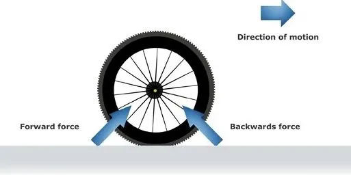
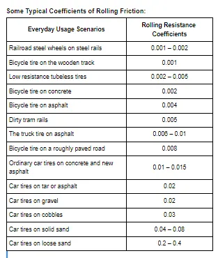
The kinetic energy of the wheels is partially converted into heat. The rolling resistance is proportional to the normal force perpendicular to the rolling wheel and is approximated by the rolling resistance coefficient urr. Hence, the Equation that can be used for the rolling resistance force of system is-
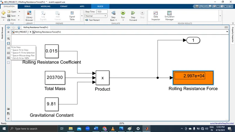
Frr = urr * m * g
where, urr= Rolling resistance co-efficient
m= Total mass of the vehicle (vehicle mass + payload) in kg
g = gravitational constant i.e 9.81 m/s^2
Here in this case for towing vehicle for aircraft taken urr= 0.015
[B]:Aerodynamic drag Force
Aerodynamic drag is a force that the oncoming air applies to a moving body. It is the resistance offered by the air to the body’s movement. So, when a car is moving, it displaces the air. However, it affects the car’s speed and performance. Technically, it is the aerodynamic drag or the friction offered by the air to a vehicle.
the aerodynamic drag force caused by the aircraft and towing vehicle can be given by Equation below
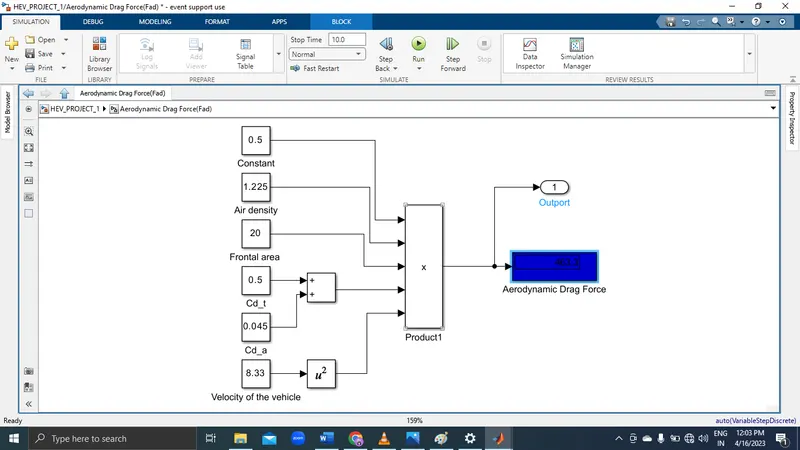
Fad = (1/2) * ρ * V^2 * A * (Cd_t + Cd_a)
where,
ρ = Air density, that is normally 1.25 kg/m^3 A = Frontal area of the vehicle in m^2 Cd_t = Air drag co-efficient of towing vehicle (It depends on frontal area, shape, protrusions, ducts, air passage etc.)
Cd_a = Air drag co-efficient of aircraft (It depends on frontal area, shape, protrusions, ducts, air passage etc.)
v = Velocity of the vehicle in m/s
With regard to the drag equation, the term A simply refers to some reference area. For airplanes, this is generally the planform area of the wing the designers design an aircraft in such a way that the reference area is optimal. So it is neglected in calculation.
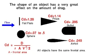
Here in this case air drag co-efficient for towing vehicle(Cd_t)= 0.5
air drag co-efficient for aircraft or payload(Cd_a)= 0.045.
[C]:-Hill climbing force is the force needed to move the vehicle in up gradient. To Hill Climbing force the expression of the equation is given below-
Fhc = m * g * sinφ
where,
m = Total mass of the vehicle(vehicle mass + payload) in kg g = Gravitational constant that is 9.8 m/s^2 φ = up gradient angle or inclination angle in radian, In this case up gradient angle(φ) = 0, as there is no inclination.
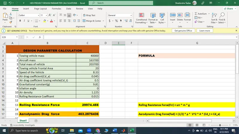
Push/Pull Power Calculation of Towing Vehicle- Let's assume, The towing vehicle mass = 40000 Kg The aircraft mass or payload on towing vehicle = 163700 Kg Total mass of the vehicle(m) = (50000+163700) = 203700 Kg Towing vehicle fontal area(A) = 20 m^2 Speed of the vehicle(V) = 30 Km/hr = 8.333 m/s
Rolling Resistance Force(Frr) = urr * m * g =0.015 * (40000+163700) * 9.81 =29974.45 N
Aerodynamic Drag Force(Fad) = (1/2) * ρ * V^2 * A * (Cd_t + Cd_a) = (1/2) * 1.225 * (8.33)^2 * 20 * (0.5+0.045) = 463.25 N
Hill Climbing Force(Fhc) = m * g * sinφ =(40000+163700) * 9.81* sin0 = 0 N
Therefore, Total Force Required to Push/Pull
the aircraft by the Towing Vehicle is: =29974.45 + 463.25 + 0 =30437.70 N
Power calculation:
= Frr * V
=30437.70*8.33
=253.54KW
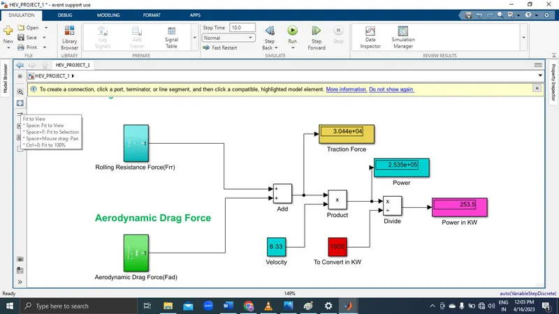
[B]: Model for the calculating force and power using Simulink.
Rolling Resistance
Aerodynamic drag Force
Q7:
SOLUTION:
Block diagram of EV powertrain
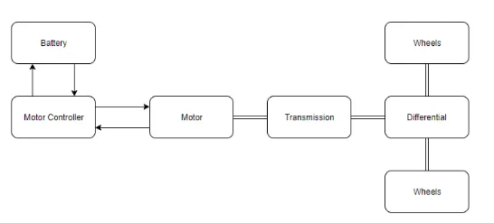
Based on the calculations done in Q. 6A
Force required to push/pull the aircraft =30.43 KN
Power required =253.54 kw
Let us assume,
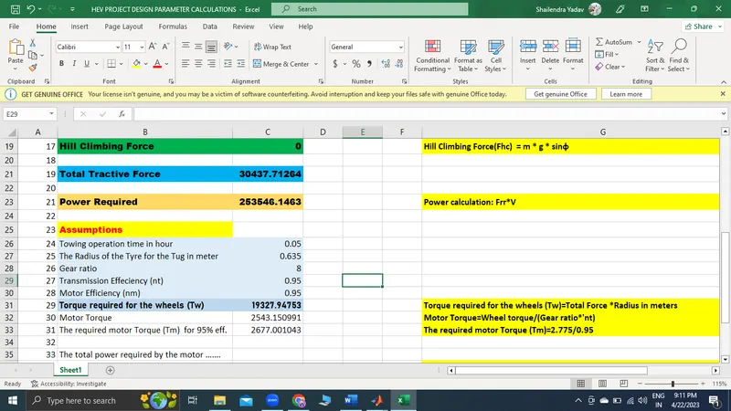
The Radius of the Tyre for the Tug - 25inches =0.635m
Gear ratio=10
Transmission Effeciency (nt) =95%
Motor Efficiency (nm)=95%
then,
Torque required for the wheels (Tw)=Total Force *Radius in meters
=30.43 *0.635
=19.32 KNm
Motor Torque=Wheel torque/(Gear ratio*'nt)
=19.32/(10*0.95)
=2.03KNm
For Motor Efficiency(nm) =95%
The required motor Torque (Tm)=2.03/0.95
=2.14 kNm
Similarly
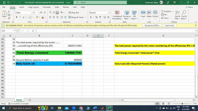
The total power required by the motor considering all the efficiencies (Pt) = 253.54/(0.95*0.95)
=280.93 Kw
Let us assume the towing operation was done for a 3 minutes (0.05Hrs) duration.
Then, Total Energy consumed = 280.93* 0.05
=14.04 KWh
If we consider the battery capacity=400 kw is used by the towing vehicle then. The duty cycle range to control the speed from O to max speed (3m/s) is given as
Duty Cycle (d)= (Required Power)/ (Rated power)
=280.93/400
=0.70
Therefore the controller will be able to provide a duty cycle ranging from 0 to 70% in order to control the towing speed.
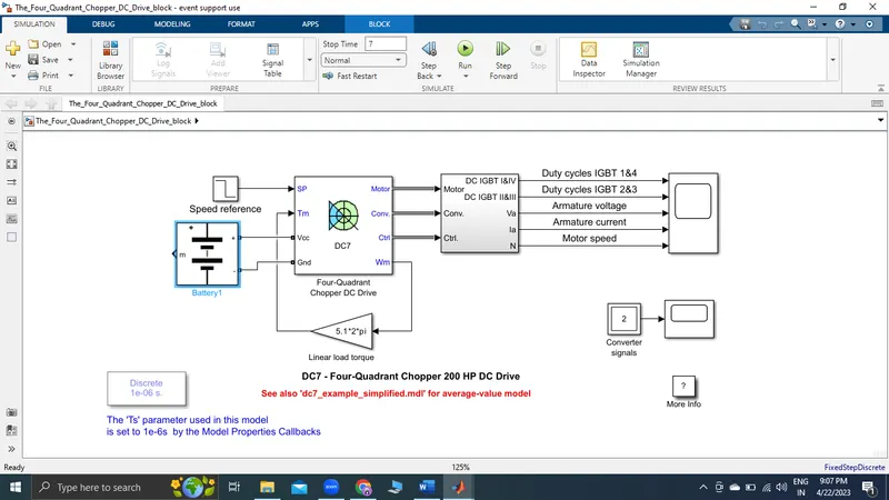
SIMULATION RESULT
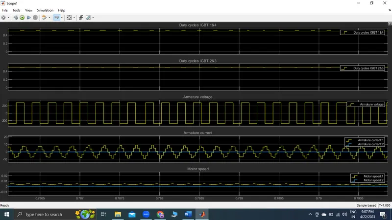
So we can say that to control the Aircraft Speed from Zero to Highest the Duty Cycle Range will be from 0 to 70% respectively.
B:Design the parameters in excel sheet.