Project-1: Powertrain for aircraft in runways
1)
|
Aircraft |
Empty Weight |
Max Fuel Weight |
Max Cargo Weight |
Max Gross Takeoff Weight |
|
Antanov AN-225 |
285,000 kg |
300,000 kg |
190,000 kg |
640,000 kg |
|
Airbus A380-800 |
277,000 kg |
254,000 kg |
84,000 kg |
575,000 kg |
|
Boeing 747-800 |
220,100 kg |
194,000 kg |
134,000 kg |
447,700 kg |
|
Airbus A340-500 |
168,000 kg |
175,000 kg |
54,000 kg |
372,000 kg |
|
Boeing 777-300ER |
168,000 kg |
145,500 kg |
67,100 kg |
352,000 kg |
|
Boeing 787-10 |
135,500 kg |
101,500 kg |
57,300 kg |
254,000 kg |
|
Boeing 737-900 |
44,700 kg |
24,000 kg |
20,200 kg |
85,000 kg |
|
Airbus A320-100 |
42,600 kg |
22,100 kg |
20,000 kg |
68,000 kg |
|
Embraer 190 |
28,800 kg |
13,000 kg |
13,100 kg |
48,000 kg |
|
Gulfstream G650 |
24,500 kg |
21900Kg |
3,000 kg |
45,200 kg |
|
Bombardier CRJ900 |
21,850 kg |
8,900 kg |
2,760 kg |
36500KG |
|
Bombardier Q400 |
17,800 kg |
5,300 kg |
8,500 kg |
28,000 kg |
|
Learjet 75 |
6,300 kg |
2,750 kg |
1,300 kg |
9,700 kg |
|
Cessna Citation CJ4 |
4,700 kg |
2,650 kg |
1,000 kg |
7,800 kg |
|
Beechcraft King Air B100 |
3,200 kg |
1,450 kg |
1,900 kg |
5,400 kg |
|
Diamond DA50 RG |
1,450 kg |
155 kg |
560 kg |
2,000 kg |
|
Beechcraft Bonanza G36 |
1,150 kg |
200 kg |
385 kg |
1,660 kg |
|
Cessna 206H |
990 kg |
235 kg |
520 kg |
1,630 kg |
|
Sirrus SR22 |
1,000 kg |
220 kg |
430 kg |
1,630 kg |
|
Cessna 172R |
770 kg |
170 kg |
255 kg |
1,100 kg |
2)
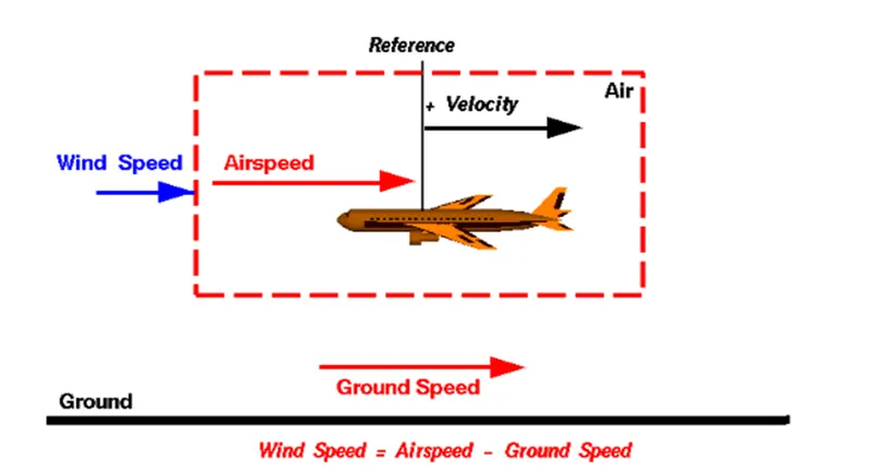
One of the most confusing concepts for young scientists is the relative velocity between objects. Aerodynamic forces are generated by an object moving through a fluid (liquid or gas). A fixed object in a static fluid does not generate aerodynamic forces. Hot air balloons "lift" because of buoyancy forces and some aircraft like the Harrier use thrust to "lift" the vehicle, but these are not examples of aerodynamic lift. To generate lift, an object must move through the air, or air must move past the object. Aerodynamic lift depends on the square of the velocity between the object and the air. Now things get confusing because not only can the object be moved through the air, but the air itself can move. To properly define the relative velocity, it is necessary to pick a fixed reference point and measure velocities relative to the fixed point. In this slide, the reference point is fixed to the ground, but it could just as easily be fixed to the aircraft itself. It is important to understand the relationships of wind speed to ground speed and airspeed.
Wind Speed :
For a reference point picked on the ground, the air moves relative to the reference point at the wind speed. Notice that the wind speed is a vector quantity and has both a magnitude and a direction. Direction is important. A 20 mph wind from the west is different from a 20 mph wind from the east. The wind has components in all three primary directions (north-south, east-west, and up-down). In this figure, we are considering only velocities along the aircraft's flight path. A positive velocity is defined to be in the direction of the aircraft's motion. We are neglecting cross winds, which occur perpendicular to the flight path but parallel to the ground, and updrafts and downdrafts, which occur perpendicular to the ground.
Ground Speed :
For a reference point picked on the ground, the aircraft moves relative to the reference point at the ground speed. Ground speed is also a vector quantity so a comparison of the ground speed to the wind speed must be done according to rules for vector comparisons.
Airspeed :
The important quantity in the generation of lift is the relative velocity between the object and the air, which is called the airspeed. Airspeed cannot be directly measured from a ground position, but must be computed from the ground speed and the wind speed. Airspeed is the vector difference between the ground speed and the wind speed.
Airspeed = Ground Speed - Wind Speed
On a perfectly still day, the airspeed is equal to the ground speed. But if the wind is blowing in the same direction that the aircraft is moving, the airspeed will be less than the ground speed.
Examples
Suppose we had an airplane that could take off on a windless day at 100 mph (liftoff airspeed is 100 mph). We are at an airport with an east-west runway that is 1 mile long. The wind is blowing 20 mph towards the west and the airplane takes off going east. The wind is blowing towards the aircraft which we call a headwind. Since we have defined a positive velocity to be in the direction of the aircraft's motion, a headwind is a negative velocity. While the plane is sitting still on the runway, it has a ground speed of 0 and an airspeed of 20 mph:
Airspeed = Ground Speed (0) - Wind Speed (-20) = 20 mph
The airplane starts its take off roll and has a constant acceleration a. From Newton's second law of motion, the ground speed V at any time t is:
V = a * t
and the distance d down the runway at any time is:
d = 1/2 * a * t^2
For a fixed length runway, this specifies the time to be used in the velocity equation. Let's assume that at 5000 feet down the runway, the velocity is 80 mph. Then the airspeed is given by
Airspeed = Ground Speed (80) - Wind Speed (-20) = 100 mph
and the airplane begins to fly. Now another pilot, with the same airplane decides to take off to the west. The wind is now in the same direction as the motion and this is called a tailwind. The sign on the wind speed is now positive, not negative as with the headwind. The acceleration along the ground is the same, so at 5000 feet down the runway, the ground speed is again 80 mph. The airspeed is then given by:
Airspeed = Ground Speed (80) - Wind Speed (20) = 60 mph
This airplane doesn't have enough airspeed to fly. It runs off the end of the runway!
Ground Speed vs Air Speed:-
As mentioned above, true airspeed is simply the speed at which an aircraft is moving relative to the air it is flying in. As such, it’s also the speed at which the air is flowing around the aircraft’s wings.
Ground speed, on the other hand, is the aircraft’s speed relative to the ground. One thing that should be noted here is that it’s its horizontal rather than vertical speed – an aircraft climbing completely vertically would have a ground speed of zero.
In other words, while airspeed is what determines whether there is enough airflow around an aircraft to make it fly, ground speed is what determines how fast an aircraft will get to its destination.
The relationship between airspeed and ground speed is simple. Ground speed is simply the sum of airspeed and wind speed.
If the aircraft is flying in the same direction as the wind is blowing, the aircraft experiences tailwind, and its ground speed is higher than its airspeed. On the other hand, if the wind is blowing against the direction the aircraft is traveling in, the aircraft experiences headwind, and its ground speed is lower than its airspeed.
3)
The term Aircraft Ground Running is usually used to describe the operation of some or all the engines of an aircraft, whilst on the ground, for the purpose of functionally checking the operation of either engines or aircraft systems. This usually takes place prior to the Release to Service of an aircraft from maintenance. Ground running may be carried out either prior to, during or after the rectification of a defect or scheduled work on an engine or an aircraft system, when this requires engines to be operating to assess its function.
The risks which may arise from engine ground running relate to the potential for loss of control of the aircraft by those persons occupying the pilot seats in the flight deck. In most cases, such persons will be maintenance personnel holding specific company-issued approval for the required tasks. The consequences of loss of control during taxi or towing are the same as apply to these operations generally and this article is concerned only with the risks arising from the static running of one or more aircraft engines. Unwanted consequences from such static running are mainly related to those arising from the unintended movement of the aircraft during engine running - effectively a loss of control especially during high power engine running. Damage can occur to the aircraft itself, other aircraft nearby or to airside structures. In addition, there is a risk of injury to ground support personnel who may be in relatively proximity to the aircraft.
The best form of overall mitigation is to ensure that all persons authorised to supervise or directly participate in engine ground running from the flight deck, who are not pilots or flight engineers currently rated on the specific aircraft type, are in receipt of suitable initial training and that there is a proper system for both initial and recurrent qualification for engine ground running duties. Both initial and recurrent qualification must include practical training and assessment of task competence using either a full flight simulator or an aircraft. Between formal competency assessments, a maximum interval between performance of the qualified task should be specified. If that interval is exceeded, the qualification would become void until remedial action has been competed. In this respect, the task of engine ground running should be seen as part of a broader group of aircraft ground movement tasks which can be carried out under the control of flight deck occupants other than type rated flight crew.
4) The aircraft is now ready for baggage to be loaded for the next flight. A so-called pushback truck reverses the aircraft into taxiing position, pushing it with a towbar attached to the nose-wheel strut. Or, in the most modern versions, by actually lifting the wheel. That speeds up coupling and decoupling. In aviation, pushback is an airport procedure during which an aircraft is pushed backwards away from an airport gate by external power. Pushbacks are carried out by special, low-profile vehicles called pushback tractors or tugs. A pushback is therefore the preferred method to move the aircraft away from the gate.
READY TO TAKE-OFF:
The pilot parks the aircraft in exactly the right place. Usually with the help of an automatic system, but occasionally guided by a marshaller waving two paddles or wands. Dozens of handling personnel are already standing by to perform a whole range of tasks simultaneously.
As soon as the aircraft is stationary and the engines are switched off, the first priority is to disembark the passengers as quickly as possible. The apron handler places chocks in front of the wheels and connects the ground power. Meanwhile, the passenger bridge manoeuvres up to the door and a belt loader rolls up to the cargo hold. Luggage is unloaded and transferred to the terminal on baggage carts.
Refuelling begins, usually from a hydrant at the stand. A hose is attached to this from a special vehicle called a dispenser, with the other side connected to the fuel tank in the wing. Read more about refuelling here.
Now it is time to service the aircraft. The caterer loads new meals and takes away the food waste and used cutlery and crockery. Other activities include draining the lavatories, replacing the headrest covers, removing rubbish and distributing fresh blankets and in-flight magazine.
A specialist team – or sometimes the crew themselves – cleans the cabin so that the new passengers board a pristine aircraft.
Meanwhile, specialists from the airline conduct a technical check to make sure that the engines, wings, control surfaces, landing gear, instruments, doors and other equipment are in full working order.
The aircraft is now ready for baggage to be loaded for the next flight. This is a quick process, on average taking only 10-15 minutes. A little later the passengers start boarding. As soon as they are all in their seats, the door is closed and the pilot informs air-traffic control that the flight is ready for departure.
The apron handler removes the chocks. A so-called pushback truck reverses the aircraft into taxiing position, pushing it with a towbar attached to the nose-wheel strut. Or, in the most modern versions, by lifting the wheel. That speeds up coupling and decoupling.
The aircraft taxis to the runway to depart at the agreed time.
The pilot waits for permission to take off from air-traffic control. This is possible once the departure route is clear. As soon as the go-ahead is received, the plane takes to the air at full power.
5)
- a) Take off power:
- Take off power can be predicted using a simple measure of the acceleration of the aircraft along the runway based on force equilibrium.
- The forces involved will be.
- T is Thrust of propulsion system pushing aircraft along the runway.
- D is Aerodynamic Drag of vehicle resisting the aircraft motion.
- F is Rolling resistance friction due to the contact of wheels or skids on the ground.
- During the take-off run, the imbalance in these forces will produce an acceleration along the runway.
- m*(dv/dt)=T-D-F
where, dv/dt is the acceleration along the runway and m is the mass of the vehicle.
- The procedure for take-off will be that the vehicle will accelerate until it reaches a safe initial flying speed.
- The pilot can then rotate the vehicle to an attitude to produce a climb lift and it will ascend from the ground The determination of this safe flying speed or rotation speed V. is a critical factor in determining take-off performance Take-off rules vary slightly depending on the aircraft category.
For Small commuter aircraft
V=1.1*VSTALL
V=1.05*V control
VSTALL =√(W/0.5CtmaxρS)
where S-Runway length
Take off power= force*displacement
(m*dv/dt)*2*s1 = (T-D-F)*S1
- b) Tyre design :
- Designing aircraft tires is a very intense undertaking The tyre is designed to withstand heavy loads while landing, take off, taxing, and parking.
- The number of wheels required for aircraft increases with the weight of the aircraft, as the weight of the aeroplane needs to be distributed more evenly.
- Aircraft tyre generates more heat during landing Aircraft drags the wheel until they match the rotational velocity of wheels.
- Due to this heat generates. Aircraft's tread pattern is designed to facilitate stability in high crosswind conditions, to channel water away to prevent hydroplaning and for braking effect.
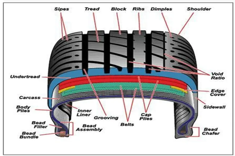
- c)Construction of tyre :
- Radial Tyre:
a ) It has fibre strands of the ply fabric oriented at 90° to the direction of rotation and the tyre sidewall.
- b) This restricts flexibility bidirectional and the flexibility of the sidewall while it strengthens the tyre to carry heavy loads.
- c) Due to their unique construction most radial tyres are resistant to penetration ad cuts. Due to stiffer tread they distribute weight evenly.
- d) Thus provide greater traction. Radial tyres have an advantage in term of reducing the heat better.
- Bias-ply Tyre:
- a) It has the fabric bias oriented with and across the direction of rotation and the sidewall.
- b) Since fabric can stretchon the bias, the tyre is flexible and can absorb loads.
- c) Tyre strength is obtained by adding plies.
- d) It is cut resistant is sidewall area.
- e) These tyres do not offer as much smoothness in terms of riding quality.
- d) Rolling Resistance:
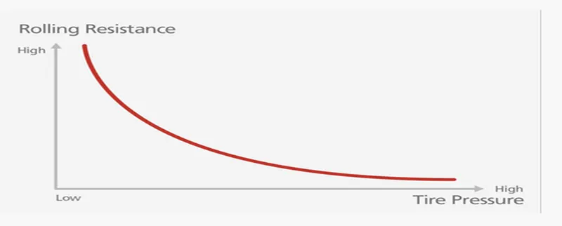
- Rolling resistance is the force resisting the motion when a body (such as ball, tyre or wheel) rolls on a surface.
- Rolling resistance can be seen in the aircraft when the aircraft takes-off from the runway & while landing at the runway with the help of their wheels
Rolling resistance can be expressed as Fm g (N).
Where
Frr the Rolling resistance(N)
μrr coefficient of rolling resistance.
m is mass(kg)
g is acceleration due to gravity= 9.81m/s^2
- e) Tyre pressure :
- Aircraft tyres operate at such high extremes of pressure, load, and speed, their care and service is critically important.
- The most important action an operator can take to prevent tyre-related events is to maintain proper tire inflation pressure.
- Failure to keep aircraft tires properly inflated can lead to very serious consequences.
- One relatively easy way to help avoid those consequences is to check tire pressures regularly and service them as necessary.
- Following these three actions is a good way to make sure you get the most value out of your tires and contribute to the safe operation of your aircraft.
- Aircraft tires are usually inflated with nitrogen to minimize expansion and contraction from extreme changes in ambient temperature and pressure experienced during flight.
- Dry nitrogen expands at the same rate as other dry atmospheric gases (normal air is about 80% nitrogen), but common compressed air sources may contain moisture, which increases the expansion rate with temperature, Also, the use of an inert gas for tire inflation eliminates the possibility of tire explosion.
Relation to Rolling Resistance and Tire Pressure :
Braking Forces during Landing :
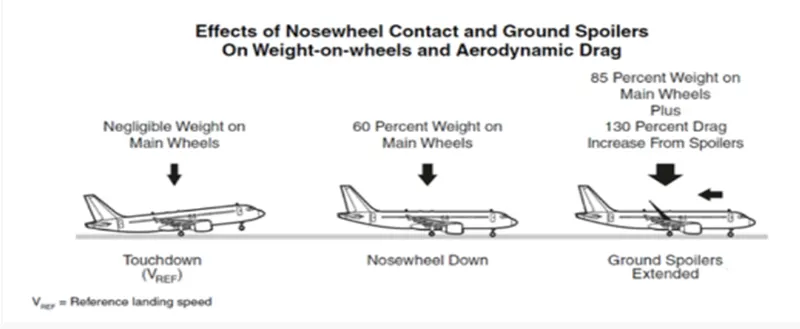
Following braking devices are used to decelerate the aircraft -
- Spoilers.
- Wheel Brakes (Including Anti-Skid systems & Auto-Brake systems)
- Reverse Thrust
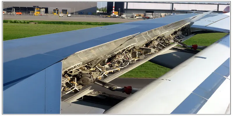
- f) Spoilers :
- The mechanical deflection of parts of the wing upper surface by increasing aerodynamic drag on the moving aircraft.
- This can be achieved by raising upper wing surface panels called ground spoilers or by operation of a tail cone 'clamshell type air brake and also by increasing the effective downward load on the landing gear and thereby increasing the efficiency of wheel braking .
6) Wheel Brakes :
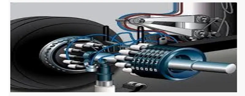
- To be effective, braking action at any speed depends upon sufficient friction existing between the tires and the runway surface achieved through freely rotating wheels.
- Anti skid system :
When landing on slippery runways, there's a chance that the wheels may start to skid as the brakes are applied. To stop this from happening and to maintain maximum effective braking, each wheel has anti-skid protection.
Using a variety of sources to determine the aircraft speed, the brake units know how fast the wheels should be spinning. If that speed drops significantly, it's because the current brake pressure on that wheel is too great and the wheel is just skidding over the surface.
In this situation, the anti-skid system automatically reduces the braking on that wheel to a point where the skid stops before reapplying the pressure.
8) Reverse Thrust :
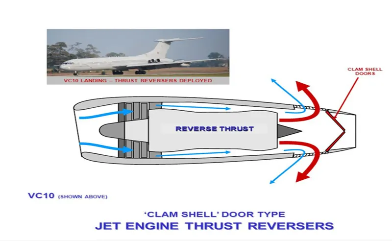
- Thrust reversers provide a deceleration force that is independent of runway condition.
- Thrust reverser efficiency is higher at high airspeed therefore.
- Treversers must be selected as early as possible after touchdown.
- Thrust reversers should be returned after reverse idle at low airspeed to prevent engine stall or foreign object damage.
7) The different forces involved when the plane is moved by a tow vehicle:
To proceed for calculating the force and power required to push or pull an aircraft by a towing vehicle, we will assume the following parameters:
Here we will consider aircraft and towing vehicle as separate units. We will also consider acting on aircraft as well as towing vehicle which are;
Rolling Friction Force
Acceleration Force
Aerodynamic drag force
We will neglect the all the losses for calculations.
The total mass of the aircraft including payload for aibus a 380 is 575,000kg
Aircraft Calculations:
Mass of aircraft, mA = 575,000kg
Mass of pushback is 1000kg(assume)
Coefficient of rolling resistance (Crr) = 0.002
Rolling resistance (Frr) = Crr * m * g
For the Aircraft, Frr = 0.002*575,000*9.81
Frr = 11.2815kN
For the Towing Vehicle, Frrt = 0.002*1000*9.81
Frrt = 19.61N
As the towing vehicle resistance is very less compared to aircraft, since it is a heavy vehicle this resistance can be neglected.
Aerodynamic resistance, (Far)
Given
Drag coefficient Cd = 0.025
Air density ρ = 1.125kg/m^2
Fronatal Area A = 150 m^2
Velocity v = 14.5kmph or 4m/s
Far = (1/2)*Cd*ρ*V^2
Far = (1/2)*0.025*1.125*150*(4)^2
Far = 33.75N
Total Force = 11281.5 + 33.75
= 11315.25 N
As the tow vehicle and plane moving at a low speed this force can be neglected
Hill Climbing resistance:
Runways are constructed flat so gradient force or hill climbing force is neglected.
Total Traction Force:
Fte = Frr
= 11281.5
Power required.
P = Ft*v
= 11315.25*4
= 45.26kW
Since the minimum power required at the tow vehicle is 45.126kW to taxi a heavy aircraft at 4m/s.
b)
7)
a)
The power required by the aircraft is 45.26kW. Consider a motor with following specifications
Voltage 400-800V
Peak Power 60-70kW
RPM 1500-4000
Torque 300Nm
Transmission
consider 60kW as peak power therefore voltage will be 400V.
Assume battery power to be 550V.
Now we can calculate the duty cycle
d=Vo/Vs
= 400/550 = 0.7272
Duty cycle is the 0.7272
Assume parameterss
Parameter value
Aircraft Mass (mA) = 575,000kg
Towing vehicle Mass =50,000kg(assume)
Rolling Resistance Co-efficient (Crr) = 0.002
Air density ρ = 1.125kg/m^2
Towing vehicle Drag coefficient Cd = 0.5
Aircraft Drag co-efficient =0.09
Fronatal Area A = 150 m^2
Inclination angle = 0 rad
Tyre Pressure = 203PSI/14 bar
Towing Velocity (V) = 14.5kmph or 4m/s
Towing Time(t) = 2 min
Radius of the towing vehicle wheel = 0.38