Project-1: Powertrain for aircraft in runways
AIM - To design the powertrain for aircraft in runways.
OBJECTIVES - 1) To list out the total weight of various types of aircrafts.
2) To describe the difference between ground speed and air speed.
3) To give the reason for why is it not recommended to use aircraft engine power to move it on the ground at Airport.
4) To describe How an aircraft is pushed to runway when its ready to take off.
5) To learn about Learn about take off power, tyre design, rolling resistance, tyre pressure, brake forces when landing.
6) To calculate the force and power required to push / pull an aircraft by a towing vehicle.
7) To Design an electric powertrain with type of motor, it’s power rating, and energy requirement to fulfill aircraft towing application. And to estimate the duty cycle range to control the aircraft speed from zero to highest.
INTRODUCTION - An aircraft is vehicle that is able to fly by gaining support from the air. It counters the force of gravity by using either static lift or by using the dynamic lift of an airfoil or in a few cases the downward thrust from jet engines. Common examples of aircraft include airplanes, helicopters, airships (including blimps),gliders etc.
An airplane is a , fixed wing aircraft that is propelled forward by thrust from a jet engine, propeller or rocket engin. Airplanes come in a variety of sizes, shapes, and wing cinfigurations. The broad spectrum of uses for airplanes includes recreation, transportation of goods and people, military, and research. Worldwide, commercial aviation transports more than four billion passengers annually on airliners and transports more than 200 billion tonne kilometers of cargo annually, which is less than 1% of the world's cargo movement. Most airplanes are flown by a pilot on board the aircraft, but some are designed to be remotely controlled or computer controlled such as drones.
some of the types of Engines or propeller in aircrafts are:
1) Reciprocating engines - Reciprocating engines in in aircraft have three main variants, radial,inline and flat or horizontally opposed. The radial engine is a reciprocating type internal combustion engine configuration in which the cylinders "radiate" outward from a central crankcase like the spokes of a wheel and was commonly used for aircraft engines before gas turbine engines became predominant. An inline engine is a reciprocating engine with banks of cylinders, one behind another, rather than rows of cylinders, with each bank having any number of cylinders, but rarely more than six, and may be water-cooled. A flat engine is an internal combustion engine with horizontally-opposed cylinders.
2) Gas turbine - A turboprop gas turbine engine consists of an intake, compressor, combustor, turbine, and a propelling nozzle, which provide power from a shaft through a reduction gearing to the propeller. The propelling nozzle provides a relatively small proportion of the thrust generated by a turboprop.
3) Electric motor - An electric air craft runs on electric motors rather than internal combustion engine, with electricity coming from fuel cells, solar cells, ultracapacitor, power beaming, or batteries. Currently, flying electric aircraft are mostly experimental prototypes, including manned and unmanned areal vehile, but there are some production models on the market already.
4) Jet - Jet aircraft are propelled by jet engine which are used because the aerodynamic limitations of propellers do not apply to jet propulsion. These engines are much more powerful than a reciprocating engine for a given size or weight and are comparatively quiet and work well at higher altitude.
PROCEDURE - For the first part - The aircraft gross weight (also known as the all-up weight and abbreviated AUW) is the total aircraft weight at any moment during the flight or ground operation. An aircraft's gross weight will decrease during a flight due to fuel and oil consumption. An aircraft's gross weight may also vary during a flight due to payload dropping or in flight refueling.
The weights are classified as following:
Maximum design taxi weight (MDTW) - The maximum design taxi weight (also known as the maximum design ramp weight (MDRW)) is the maximum weight certificated for aircraft manoeuvring on the ground (taxiing or towing) as limited by aircraft strength and airworthiness requirements.
Maximum design takeoff weight (MDTOW) - It is the maximum certificated design weight when the brakes are released for takeoff and is the greatest weight for which compliance with the relevant structural and engineering requirements has been demonstrated by the manufacturer.
Maximum design landing weight (MDLW) - The maximum certificated design weight at which the aircraft meets the appropriate landing certification requirements. It generally depends on the landing gear strength or the landing impact loads on certain parts of the wing structure. The maximum landing weight is typically designed for 10 feet per second (600 feet per minute) sink rate at touch down with no structural damage.
Maximum design zero fuel weight (MDZFW) - The maximum certificated design weight of the aircraft less all usable fuel and other specified usable agents (engine injection fluid, and other consumable propulsion agents). It is the maximum weight permitted before usable fuel and other specified usable fluids are loaded in specified sections of the airplane. The MDZFW is limited by strength and airworthiness requirements. At this weight, the subsequent addition of fuel will not result in the aircraft design strength being exceeded.
Manufacuturer's empty weight (MEW) - It is the weight of the aircraft "as built" and includes the weight of the structure, power plant, furnishings, installations, systems and other equipment that are considered an integral part of an aircraft. This excludes any baggage, passengers, or usable fuel.
Pay load - It is the carrying capacity of an aircraft. It includes cargo, people, extra fuel. In the case of a commercial airliner, it may refer only to revenue-generating cargo or paying passengers.
Operating empty weight (OEW) - It is the basic weight of an aircraft including the crew, all fluids necessary for operation such as engine oil, engine coolant, water, unusable fuel and all operator items and equipment required for flight but excluding usable fuel and the payload.
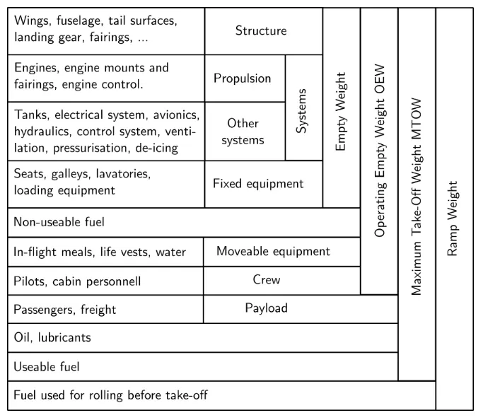
In the above fig. Boxes on the right sum up the separate items which they run across. To simply this :
- Dry Operating Wieght (DOW) OEW + Weight of Crew (Pilot + Cabin including their bags) + Pantry
- Operating Weight (OW) DOW + Takeoff fuel (i.e. Ramp Fuel - Taxi fuel)
- Maximum Zero Fuel Weight (MZFW) DOW + Payload (anything put on the aircraft that generates revenue to the company, e.g. passenger, baggage, cargo, mail and fret)
- Maximum Taxi Weight (MTW) MZFW + Ramp fuel
- Maximum Takeoff Weight (MTOW) MZFW + Takeoff fuel, or MTW - Taxi fuel
- Maximum Landing Weight (MLW) MTOW - Trip Fuel
The total weights of various types of aircraft are shown below:
- Airbus A330-800F – 1,117,882 pounds (507,063 kg)
- Boeing 747-400 – 875,014 pounds (396,900 kg)
- Lockheed C-5 Galaxy – 839,961 pounds (381,000 kg)
- McDonnel Douglas MD-11 – 602,523 pounds (273,300 kg)
- Boeing 767-400ER – 449,743 pounds (204,000 kg)
- Concorde – 407,855 pounds (185,000 kg)
- Boeing 727-100 – 159,835 pounds (72,500 kg)
some more examples are shown below:
| Type | MTOW [kg] | MLW [tonnes] | TOR [m] | LR [m] |
|---|---|---|---|---|
| Airbus A220-100 | 59,000 | 50.80 | 1463 | 1356 |
| Airbus A220-300 | 65,000 | 57.61 | 1890 | 1494 |
| Airbus A300-600 | 163,000 | 138 | 2324 | 1536 |
| Airbus A300-600R | 192,000 | 140 | 2385 | 1555 |
| Airbus A310-200 | 142,000 | 123 | 1860 | 1480 |
| Airbus A310-300 | 157,000 | 124 | 2290 | 1490 |
| Airbus A318 | 59,000 | 57.5 | 1375 | 1340 |
| Airbus A319 | 64,000 | 62.5 | 1850 | 1470 |
| Airbus A320-100 | 68,000 | 66 | 1955 | 1490 |
| Airbus A321-100 | 83,000 | 77.8 | 2200 | 1540 |
| Airbus A330-200 | 242,000 | 180 | 2220 | 1750 |
| Airbus A330-300 | 242,000 | 185 | 2500 | 1750 |
| Airbus A340-200 | 253,500 | 181 | 2990 | |
| Airbus A340-300 | 276,700 | 190 | 3000 | 1926 |
| Airbus A340-500 | 371,950 | 240 | 3050 | 2010 |
| Airbus A340-600 | 367,400 | 256 | 3100 | 2100 |
| Airbus A350-900 | 270,000 | 175 | 2670 | 1860 |
| Airbus A350-1000 | 308,000 | 233.5 | ||
| Airbus A380-800 | 575,000 | 394 | 3100 | 1930 |
| Airbus A400M | 141,000 | 122 | 980 | 770 |
Here MTOW is Maximum Take Off Weight
MLW is Maximum Landing Weight
TOR is Take Off Run
LR is Landing Run
For the second part - when we talk about speeds of aircraft there are two types of speed in aircraft One is the ground speed and other is the air speed
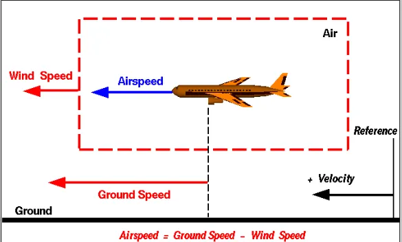
Ground speed - It is the airplane's speed relative to earth's surface. One thing that should be noted here is that it’s its horizontal rather than vertical speed – an aircraft climbing completely vertically would have a ground speed of zero.
Air speed - It is the airplane's speed relative to the air it is flying in. Air speed is what determines whether there is enough airflow around an aircraft to make it fly.
There are three types of air speed:
Indicated air speed - It is an air speed that is calculated directly off an aircraft’s pitot-static system. It’s the calculated off the aircraft’s dynamic pressure – the difference between its total pressure and static pressure. The dynamic pressure depends not only on the aircraft’s speed, but also on the density of the air it is flying in. As such, the higher the aircraft flies – and the lower the air density as a result – the bigger the difference between indicated and true air speed.
Caliberated air speed - It is indicated air speed adjusted for a variety of errors.Just as an example, one of the things it’s adjusted for is the flap position. The reason for that is that at different flap positions, air flows differently around the pitot-static system and affects the indicated airspeed readings.
True air speed - It is the actual speed at which an aircraft is moving relative to the air it is traveling in. It’s calibrated airspeed adjusted for the the exact conditions (altitude, air temperature, etc.) that the aircraft is flying in.
The relationship between airspeed and ground speed is fairly simple. Ground speed is simply the sum of airspeed and wind speed. If the aircraft is flying in the same direction as the wind is blowing, the aircraft experiences tailwind, and its ground speed is higher than its airspeed. On the other hand, if the wind is blowing against the direction the aircraft is traveling in, the aircraft experiences headwind, and its ground speed is lower than its airspeed.
To give you an actual example, imagine an aircraft that cruises at an airspeed of 500 miles per hour that has to cover a ground distance of 2,000 miles.If there is no wind at all, then both the aircraft’s airspeed and ground speed would be the same 500 miles per hour, and the aircraft would reach its destination in four hours.
If there was a 100 miles per hour headwind – wind blowing against the aircraft’s direction of travel – the aircraft would still be traveling at an airspeed of 500 miles per hour. However, its ground speed would be just 400 miles per hour (100 miles per hour slower than its airspeed). And as such, it would take the aircraft five hours to reach its destinations.
Finally, if there was a 100 miles per hour tailwind – wind blowing in the same direction as the aircraft’s travel – the aircraft would still be traveling at an airspeed of 500 miles per hour, but its ground speed would be 100 miles faster.And, at 600 miles an hour, the aircraft would reach its destination in just three hours and twenty minutes.
The above is the reason why some flights go “out of their way” to avoid headwinds or catch tailwinds. And, why some flights might appear to be traveling at “supersonic speeds,” even though their airspeed – the speed that would actually matter in determining whether or not the flight truly is supersonic – is subsonic.
For pilots, both airspeed and ground speed are very important. While the first of those helps them make sure they are flying fast enough to take off, not to stall, and so on, the second one helps them figure out how long it will take them to get from one place to another. On the other hand, if you are a passenger, you will only need to be concerned about the ground speed as that will tell you how fast are you flying from your origin to your destination – how fast you will be able to get to your meeting, meet your relatives, or do whatever else the reason for your travel might be.
For the third part -
There are number of reasons that to not use aircraft's engine to move it on the ground and they are:
1) Aircraft's engine creates a huge noise around which is not good for surrounding's around the airport.
2) Huge amount of fuel is consumed by the engine which is again is a disadvantage. so by taxiing fuel can be saved for the aircraft's flight.
3) If engine power is used by the aircraft for its travel to runway it will cause wear and tear to the engine and we don't want that before a flight cause it will create unnecessary problems to both the passangers and airport staff.
4) It will cause various injuries and damage to the near by population and property if a pilot losses control of the airplane traveling on the ground using engine power
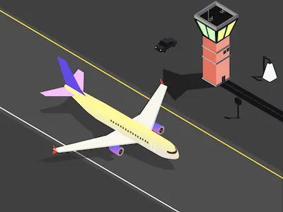
For the fourth part - The term that is used when the aircraft is moved from the hanger to the runway is "TAXIING" which is defined as the movement of an aircraft on the ground, under its own power, in contrast to towing or pushback where the aircraft is moved by a tugAn airplane uses taxiways to taxi from one place on an airport to another. The term "taxiing" is not used for the accelerating run along a runway prior to takeoff, or the decelerating run immediately after landing, which are called the takeoff roll and landing rollout, respectively.
Taxiways, too, can vary in width and load-bearing strength depending on the airfield. Depending on these factors, they are categorized so that pilots know which taxiways they are able to use for their aircraft type. The taxiways at some airports can be particularly tight, especially for bigger aircraft. With a wingspan of more than 60 meters, pilots on the 787 Dreamliner always have to be mindful of their wingtips. Given below is an image of airplane taxiing on its own.
Another way to move the aircraft on the ground that is "TOWING" which is defined as coupling two or more objects together so that they may be pulled by a designated power source or sources. The towing source may be a motorized land vehicle, vessel, animal, or human, and the load being anything that can be pulled. These may be joined by a chain, rope, bar, hitch, three-point, fifth-wheel, coupling, drawbar, integrated platform, or other means of keeping the objects together while in motion.
The most familiar form is the transport of disabled or otherwise indisposed vehicles by a tow truck or "wrecker." Other familiar forms are the tractor-trailer combination, and cargo or leisure vehicles coupled via ball or pintle and gudgeon trailer hitches to smaller trucks and cars. In the opposite extreme are extremely heavy duty tank recovery vehicles, and enormous ballast-tractors involved in heavy howling towing loads stretching into the millions of pounds.
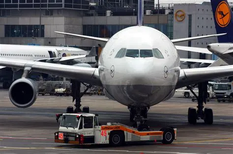
Due to the reasons mentioned above in the above section towing of aircarft is necessary. here towing vehicle is operated by a driver which will pull the airplane from tha hanger to the runway when it is ready to takeoff or it will take the airplane from runway to the parking area(hanger) after landing. An example of towing is shown below in which an towing vehicle is pulling the aircraft to the runway.
Most of the aircraft use pushback tug because airplanes unlike cars does not have a reverse gear. For smaller aircraft, the pushback tug doesn’t require a massive amount of power. They utilize the weight of the tug, sometimes up to 60 tons, to ensure that the wheels don’t just spin on the tarmac.
Getting around some airports can be quite challenging. Taxiways seem to go all over the place, with some ending in dead ends and others leading onto runways. As a result, pilots have to keep their wits about them. To help us, taxiways are given an alphanumeric name to help differentiate them from one another. These are then depicted on a map of the airport, which is provided to the pilots.
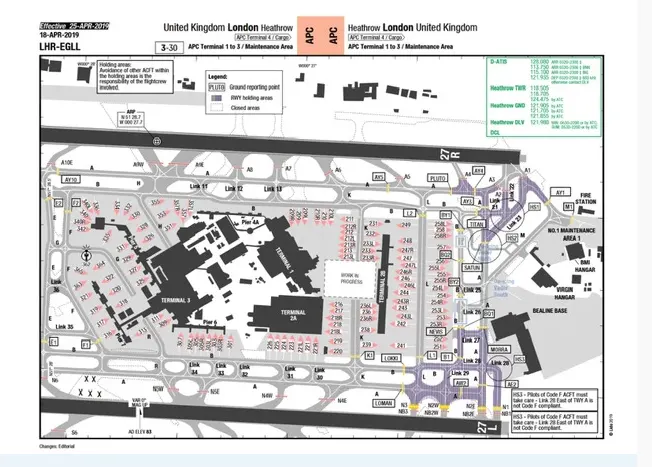
The above shown is a navigation chart which pilots use and it is very much like the navigation system in your car. Pilots are able to see exactly where the aircraft is in relation to the runways and taxiways around it. This is particularly useful at night or when the weather is bad, giving pilots greater spatial awareness and reducing errors as a result.
Rules ragarding Taxiing - As a general rule, only rated pilots and qualified airframe and powerplant (A&P) technicians are authorized to start, run up, and taxi aircraft. All taxiing operations are performed in accordance with applicable local regulations.
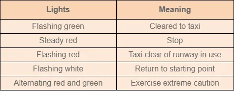
The above fig. contains the standard taxi light signals used by control towers to control and expedite the taxiing of aircraft. Here a signal man will be there to direct the towing aircraft and pilot to properly execute the operation that is taxiing.
The standard position for a signalman is slightly ahead of and in line with the aircraft’s left wingtip. As the signalman faces the aircraft, the nose of the aircraft is on the left. The signalman must stay far enough ahead of the wingtip to remain in the pilot’s field of vision. It is a good practice to perform a foolproof test to be sure the pilot can see all signals. If the signalman can see the pilot’s eyes, the pilot can see the signals.some of the sognals are shown which is executed by the signaman.
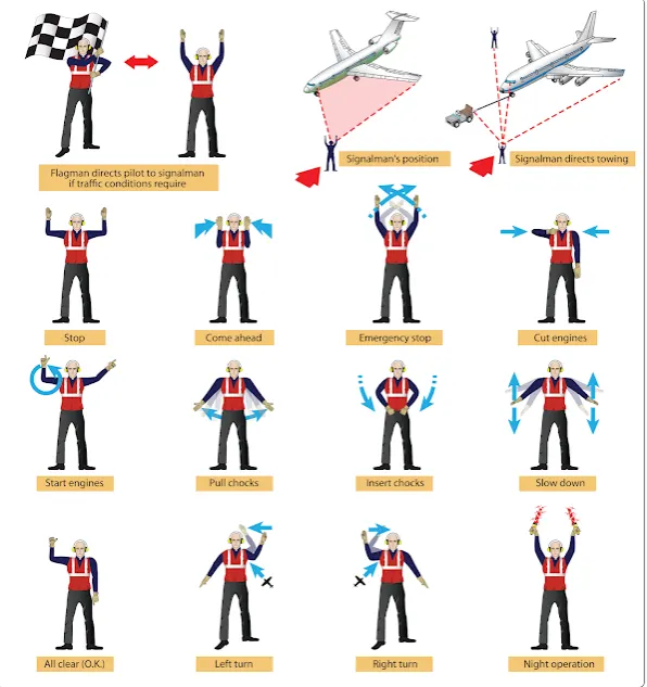
The taxi signals to be used must be studied until the taxi signalman can execute them clearly and precisely. The signals are to be given in such a way that the pilot cannot confuse their meaning. The signalman is to always try to give the pilot an indication of the approximate area that the aircraft is to be parked. The signalman must glance behind himself or herself often when walking backward to prevent backing into a propeller or tripping over a chock, fire bottle, tie-down line, or other obstruction.
For the fifth part - Take off power - Take off is a phase of flight in which an aerospace vehicle leaves the ground and becomes airborne. For light aircarft, usually full power is used during takeoff. Large transport catagory (airliner) aircraft may use a reduced power for takeoff, where less than full power is applied in order to prolong engine life, reduce maintenance costs and reduce noise emissions. In some emergency cases, the power used can then be increased to increase the aircraft's performance. Before takeoff, the engines, particularly piston engine, are routinely run up at high power to check for engine-related problems.
Fixed-wing aircraft designed for high-speed operation (such as commercial jet aircraft) have difficulty generating enough lift at the low speeds encountered during takeoff. These are therefore fitted with high-lift devices, often including slats and usually flaps, which increase the camber and often area of the wing, making it more effective at low speed, thus creating more lift. These are deployed from the wing before takeoff, and retracted during the climb. They can also be deployed at other times, such as before landing.
Power by the definition we know that it is aproduct of force and velocity. So the force required or the forces considered during the take off are mention below:
Thrust - Thrust is the force generated by the engine of aircraft to move it through the air. To maintain level flight at constant speed, constant thrust is required; to climb or descend the aircraft whilst maintaining constant speed, the thrust must be increased or decreased; to increase or reduce the speed of the aircraft whilst maintaining level flight, the thrust must be increased or decreased.
Drag - Drag is a force that that oppose the relative motion of an object through the air. Drag always opposes the motion of the object. so in aircraft the force that acts opposite to thrust is called drag.
weight - The force that acts due to gravity. It includes the total weight of the aircraft.
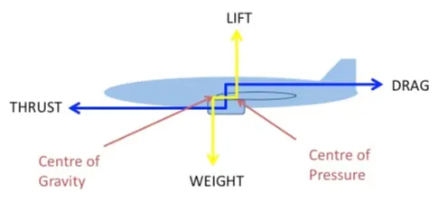
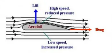
Lift - Air flow past an airplane exerts a force on the surface. The component of this force perpendicular to the air flow is called the lift. The airflow over the wing increases its speed causing a reduction in pressure; this generates a force (lift) perpendicular to the chord of the aerofoil. The airflow below the wing moves much more slowly generating greater pressure and less or negative lift.
Total power will be the addition of all the forces.
Total force = (Thrust) + (Weight) + (Drag) + (Lift) + (rolling resistance)
power required = (Total force)*(velocity of aircraft)
Tyre design - An aircraft tyre is designed to withstand extremely heavy loads while landing, take off, taxing and parking. The number of wheels required for aircraft increases with the weight of the aircraft, as the weight of the aeroplane needs to be distributed more evenly. Engineers are challenged with designing tires with cool running, heat-resistant materials while simultaneously exceeding tire service requirements. Tire prototypes are put through rigorous tests that simulate cycles of landings, take-offs, and taxi operations. It is only after the tires pass all mandatory tests and meet the requirements of the aircraft manufacturer and airworthiness authorities that the tires are put into production.

Two types of tyre are used in aircraft application, and those are bias-ply tyre and radial tyre.
1) Bias-ply tyre - Bias-ply tires are popular choices for aircraft tires because of their durability and retreadability. The tire construction consists of the following components: The cross section of bias tyre is shown below:
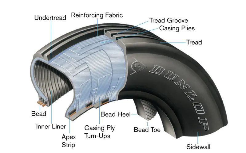
Tread: The tread is made of rubber mixed with other additives to obtain the desired level of toughness, durability, and resistance to wear.
Sidewall: The sidewall is a protective layer of rubber that covers the outer casing ply. It extends from the tread edge to the bead area.
Buff Line Cushion: The buff line cushion is made of rubber compound to enhance the adhesion between the tread reinforcing ply and the breakers or casing plies.
Breakers: Breakers are reinforcing plies of rubber-coated fabric placed under the buff line cushion to protect casing plies and strengthen and stabilize the tread area.
Casing Plies: Alternate layers of rubber-coated fabric (running at opposite angles to one another) provide the strength of the tire.
Wire Beads: Hoops of high tensile strength steel wire that anchor the casing plies and provide a firm mounting surface on the wheel. The outer edge of the bead that fits against the wheel flange is called the bead heel. The inner bead edge is called the bead toe.
Apex Strip: A wedge of rubber affixed to the top of the bead bundle.
Flippers: Layers of rubberized fabric that help anchor the bead wires to the casing and improve the durability of the tire.
Ply Turnups: The casing plies are anchored by wrapping them around the wire beads, thus forming the ply turnups.
Chafer: A protective layer of rubber and/or fabric located between the casing plies and wheel to minimize chafing.
Liner: In tubeless tires, the liner is a layer of low permeability rubber that acts as a built-in tube and restricts gas from diffusing into the casing plies. In tube-type tires, a thinner liner is used to prevent tube chafing against the inside ply.
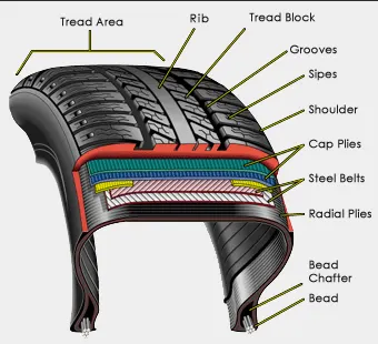
2) Radial type - A typical radial tyre With their rigid belt, they provide increased landings and reduced rolling resistance. They have fewer components in their construction and are lighter than similarly sized bias ply tires. Components that differ from bias-ply construction as follows:
Overlay: A layer of reinforcing rubber coated fabric placed on top of the belts to aid in high speed operation.
Belt Plies: A composite structure that stiffens the tread area for increased landings. The belt plies increase the tire strength in the tread area.
Casing Plies: As in bias-ply tires, the casing plies are layers of rubber-coated fabric. However, unlike those in bias plies that run at opposite angles to one another, radial plies run radially from bead to bead.
Chippers: The chippers are layers of rubber-coated fabric applied at diagonal angles that improve the durability of the tire in the bead area.
Rolling resistance - Rolling resistance sometimes called rolling friction or rolling drag, is the force resisting the motion when a body (such as a ball, tyre, or wheel) rolls on a surface. It is mainly caused by non-elastic effects; that is, not all the energy needed for deformation (or movement) of the wheel, roadbed, etc., is recovered when the pressure is removed. Another cause of rolling resistance lies in the slippage between the wheel and the surface, which dissipates energy.
In aircraft the friction between aircraft and runway will be proportional to the normal force exerted by the aircraft on the runway. so rolling resistance force is given by
F = crr*(W-L)
The normal force will be the difference between Weight of aircraft and Lift, the friction coefficient or the coefficient of rolling resistance(crr) will be typically of a magnitude of 0.02 for a standard tarmac runway.
Tyre pressure - An aircraft tyre or tyre is designed to withstand extremely heavy loads for short durations. The number of tires required for aircraft increases with the weight of the aircraft, as the weight of the airplane needs to be distributed more evenly. Aircraft tire tread patterns are designed to facilitate stability in high crosswind conditions, to channel water away to prevent hydroplaning, and for braking effect.
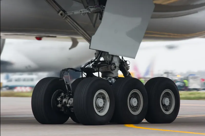
The above shown image is of Boeing 777-300ER plane. This plane has twelve main tyres and each is inflated to 220 psi (15 bar; 1,500 kPa), weighs 120 kg (260 lb), has a diameter of 134 cm (53 in) and is changed every 300 cycles while the brake are changed every 2000 cycles.
Aircraft tires generally operate at high pressures, up to 200 psi (14 bar; 1,400 kpa) for airliners, and even higher for business jets. The main landing gear on the concorde was typically inflated to 232 psi (16.0 bar), whilst its tail bumper gear tires were as high as 294 psi (20.3 bar). The high pressure and weight load on the Concorde tyres were a significant factor in the loss of Air France flight.
Tests of airliner aircraft tires have shown that they are able to sustain pressures of maximum 800 psi (55 bar; 5,500 kPa) before bursting. During the tests the tires have to be filled with water, to prevent the test room being blown apart by the energy that would be released by a gas when the tire bursts. Aircraft tires are usually inflated with nitrogen to minimize expansion and contraction from extreme changes in ambient temperature and pressure experienced during flight. Dry nitrogen expands at the same rate as other dry atmospheric gases (normal air is about 80% nitrogen), but common compressed air sources may contain moisture, which increases the expansion rate with temperature. The use of inert gas in tyre inflation eliminates the chances of explosion.
Brake force when landing - Aircraft brakes stop a moving aircraft by converting its kinetic energy to heat energy by means of friction between rotating and stationary discs located in brake assemblies in the wheels. Brakes provide this critical stopping function during landings to enable airplanes to stop within the length of the runway. They also stop aircraft during rejected takeoff events, in which an attempted takeoff is canceled as the airplane is rolling down the runway before it lifts off from the ground due to engine failure, tire blowout, other system failure or direction from air traffic control.
Aircraft brakes also prevent motion of the aircraft when it is parked, limit its speed during taxiing and can even help steer the aircraft on the ground by applying different levels of braking force to the left- and right-side brakes.
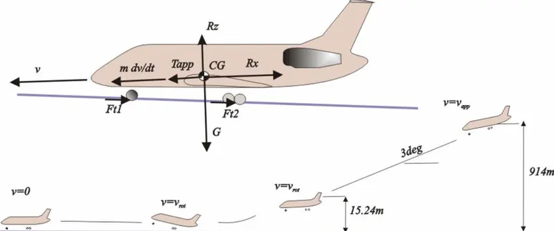
The touch down velocity should be approximately the stall speed of the aircraft in landing configuration. This will be achieved by increasing the drag and decelerate the aircraft to minimum flying speed.The deceleration on the landing roll will be accomplished by braking and reverse thrust.
The brake force required will be calculated by following equation:
dvdt=-(T+F+D)m">dvdt=−(T+F+D)mdvdt=-(T+F+D)m
here T is the thrust force
D is the aerodynamic drag force
F is the rolling resistance force
m is the mass of the aircraft
and this -(dv/dt) will be deceleration
so brake force required will be mass*deceleration
For the sixth part - The forces that will act on the towing vehicle while pushing/pulling an aircraft are as follows:
Here iam assuming the towing vehicle and craft is moving with a constant speed so acceleration forces wii be 0 and also the hill climbing force is also 0 because the towing vehicle is traveling on flat surface.
1) Rolling resistance force
2) Aeradynamic drag force
1) Rolling resistance force - Rolling resistance sometimes called rolling friction or rolling drag, is the force resisting the motion when a body (such as a ball, tyre, or wheel) rolls on a surface. It is mainly caused by non-elastic effects; that is, not all the energy needed for deformation (or movement) of the wheel, roadbed, etc., is recovered when the pressure is removed. Another cause of rolling resistance lies in the slippage between the wheel and the surface, which dissipates energy.
the magnitude of Rolling resistance force is fiven by Fr = crr*m*g
where crr is the coefficient of rolling resistance
m is the total mass of the vehicle, Total mass (vehicle mass + pay load)
g is the acceleration due to gravity
2) Aerodynamic drag force - drag (sometimes called air resistance, a type of friction, or fluid resistance, another type of friction or fluid friction) is a force acting opposite to the relative motion of any object moving with respect to a surrounding fluid. This can exist between two fluid layers (or surfaces) or a fluid and a solid surface. Unlike other resistive forces, such as dry friction, which are nearly independent of velocity, drag force depends on velocity. so basically the darg force will resist the motion of an object.\
The magnitude of drag force is given by Fd = 12⋅e⋅A⋅cd⋅V2">12⋅e⋅A⋅cd⋅V212⋅e⋅A⋅cd⋅V2
here e is the density of air in kg/m^3
A is the frontal area
Cd is the drag coefficient
V is the velocity of vehicle in m/s
so for calculating the forces and power i have created an excel sheet of the towing vehicle and it is shown below:

Here i have assumed the weight of towing vehicle as 40000kg and i have taken the Airbus A350 aircraft as my airplane which is being towed by the towing vehicle. The weight of Airbus A350 is 270000 kg.
The other parameters i have assumed are
Coefficient for rolling resistance for towing vehicle =0.13
coefficient of rolling resistance for aircraft = 0.2
Coefficient of drag for towing vehicle = 0.3
coefficient of drag for aircraft = 0.05 (here it is low because first the effect of air will be on the vehicle and then it will affect the aircraft)
speed i have assumed here is 2.5m/s it will be low because the towing vehicle will not run at high speed while pushing/pulling the aircraft
Then i have simply calculated rolling resistance force and drag force for both towing vehicle and aircraft and i have summed up both to get the total force. So here the total force i got was 580818.7969 N or 580.18 KN
The total power in kW i got was 1452.046 KW by multiplying Total force and velocity.
For the seventh part - For this purpose i have to design an electric powertrain for the towing vehicle.
Power train - The power tarin provides power to vehicle. Power train refers to the set of components that generate the power required to move the vehicle and deliver it to the wheels.
An electric powertrain has 60% fewer components than the powertrain of the IC engine vehicle. The components that forms an electric power train are
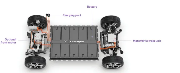
1) Battery - The battery is a component which will give power to the electric motor. The batteries generally used in electic vehicles are Lithium ion type. Battery also stores the energy.
2) power electronics converter - Power electronic technology deals with processing and controlling the flow of electrical energy in order to supply voltages and currents in a form that optimally suited for end user’s requirements. A power electronic converter uses power electronic components such as SCRs, TRIACs, IGBTs, etc. to control and convert the electric power. The main aim of the converter is to produce conditioning power with respect to a certain application.
The types of power converters used in electic vehicles are :
- AC to DC converter - converts AC input signal into DC.
- DC to DC converter - converts DC input siganl into DC. Also called chopper beacuse the output we get here is chopped.
- DC to AC converter - converts DC iinput signal into AC.
3) Electric motor - The electric motor converts electrical energy into mechanical that is delivered to the wheels via transmission system.
4) Motor controller - Motor controller is used to control the output of the motor as per the drivers requirement.
5) Transmission system - Transmission system is a system consisting of gears which will transmit the power to the wheels.
Here for designing the elecric power train i have assumed that my towing vehicle is going to pull an 'Airbus A319' so here again i will calculate all the forces that will be exerted on both the vehicle and aircraft.
Here i am neglecting the aceleration forces because there is no change in speed of the vehicle and aircraft as it moving with a constant speed. Also iam neglecting the hill climbing force because the vehicle is moving on a flat surface.
so two forces will be acting on both vehicle and aircraft. The first is the Rolling resistance force and second is the Aerodynamic drag force.
The parameters i have assumed for calculations are shown below in table:
| S.NO | PARAMETERS | VALUES |
| 1 | Weight of Towing vehicle | 40000 kg |
| 2 | Weight of Airbus A319 | 64000kg |
| 3 | Coefficient of Rolling resistance (Towing vehicle) | 0.06 |
| 4 | Coefficient of Rolling resistance (Airbus A319) | 0.08 |
| 5 | Fontal area (Towing vehicle) | 15 m2">m2m2 |
| 6 | Frontal area (Airbus A319) | 32 m2">m2m2 |
| 7 | Coefficient of drag(Towing vehicle) | 0.3 |
| 8 | Coefficient of drag(Airbus A319) | 0.1 |
| 9 | Density of air | 1.25 kgm3">kgm3kgm3 |
| 10 | speed | 5 m/s |
| 11 | Motor efficiency | 0.90 |
| 12 | Transmission efficiency | 0.80 |
| 13 | Gear ratio | 5 |
| 14 | Tyre radius of towing vehicle | 20 inches |
First calculating the rolling resistance force by formulae Fr = crr⋅m⋅g">crr⋅m⋅gcrr⋅m⋅g
Rolling resistance force (fr1) for vehicle = 0.06⋅9.81⋅40000">0.06⋅9.81⋅400000.06⋅9.81⋅40000 = 23544 N or 23.544 KN
Rolling resistance force(fr2) for aircraft = 0.08⋅9.81⋅64000">0.08⋅9.81⋅640000.08⋅9.81⋅64000= 50227 N or 50.227 KN
Total rolling resistance force (fr1 + fr2) = 73771 N or 73.771 KN
Now calculating drag force by the formulae Fd = 12⋅e⋅cd⋅A⋅v2">12⋅e⋅cd⋅A⋅v212⋅e⋅cd⋅A⋅v2
Drag force (fd1) for Towing vehicle = 12⋅1.25⋅0.3⋅15⋅52">12⋅1.25⋅0.3⋅15⋅5212⋅1.25⋅0.3⋅15⋅52 = 70.132 N
Drag force (fd2) for aircraft = 12⋅1.25⋅32⋅0.1⋅52">12⋅1.25⋅32⋅0.1⋅5212⋅1.25⋅32⋅0.1⋅52 = 50 N
Total drag force (fd1 + fd2) = 120.132 N
Total force ( total rolling resistance + total drag force) = (73771 + 120.132) = 73891.132 N or 73.891 KN
Total power required = (Total force * velocity)
Total power required in KW = ( 73891.132⋅5">73891.132⋅573891.132⋅5) = 369.455 KW
Here i have assumed the gear ratio (G) as 5 and efficiency of gear system i have assumed is 0.8, and motor efficiency i have assumed is 0.9
so calculating the actual power considering all the efficiencies
power required (KW) = 369.4550.8⋅0.9">369.4550.8⋅0.9369.4550.8⋅0.9 = 513.13 KW
Tyre radius for the towing vehicle i have assumed here is 20 inches or 0.508 m
Now i will calculate the Torque required at the wheels by the Torque formuale wich is given by the product of Total force and tyre radius
(Torque) = (Total force)*(Tyre radius)
(Torque) = (73891.132)*(0.508)
(Torque) = 37.536 KN m
Now i will calculate the motor torque by the following formulae
Motor torque = (T)wheelG⋅n">(T)wheelG⋅n(T)wheelG⋅n
Here T is the wheel torque
G is the gear ratio
n is the efficiency of the gear system
Motor Torque = 37.5365⋅0.8">37.5365⋅0.837.5365⋅0.8
Motor Torque = 9.384 KN m
Now considering the motor efficiency is well so actual Motor torque will be
(T)motor = 9.3840.9">9.3840.99.3840.9 = 10.426 KN m
Now i am assuming that the towing time is 20 minutes meaning the towing vehicle is taking 20 minutes to pull the aircraft from the hanger to the runway.
Actual power required is 513.13 KW
Total energy consumed in that process is given by
converting 20 minutes in hours that is 0.33 hours
Total energy = 513.13*0.33 = 169.33
Total energy consumed is 169.33 KWh
so a battery of higher capacity than 169.33 KWh should be selected to perform the operation.
So if i use a battery capacity of 180 KWh which if runs for 20 mins will produce 545.45 or approx 546 KW power which is higher than my actual power so it will be able to run my towing vehicle.
For duty cycle range lets see first what is duty cycle
Duty cycle - Duty cycle is a parameter that is measured in percentage which shows the amount of time the switch is on.
Duty cycle = (Time)onTotaltime">(Time)onTotaltime(Time)onTotaltime
Total time = (Time)on + (Time)off
Duty cycle basically controls the output voltage.
Duty cycle = 513546">513546513546 = 0.93
this means that if i want to my towing vehicle for 20 minutes with a speed of 5 m/s i have to set the duty cycle range as (0 to 0.93)
0 shows the starting condition that the vehicle is starting and 0.93 shows that vehicle has reached the highest speed which in my case is 5m/s.
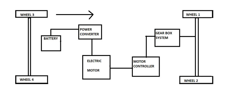
The above fig shows the block diagram for the electric power train of towing vehicle. here you can see that all the components are connected in series the power train starts with battery which will give power to the electric motor through power converter. The electric motor is further connected with motor controller to control the output as per drivers requirement and finally the motor controller is connected to transmission system which will transmit the power to the wheels.
RESULT - 1) The total weight of various aircarft was menioned in the above section.
2) The difference between the ground speed and air speed was mentioned in the above section
3) The reason for not using aircraft engine power to move it on the ground was also mentioned in the above section.
4) The description of how an aircraft is pushed to runway when it is ready to take off was mentioned in the above section.
6) The force required in my case with my assumed values to push/pull an aircraft by towing vehicle was found out as 580.18 KN
The power required in my case with my assumed values to push/pull an aircraft by towing vehicle was found out as 14520.46 KW
7) For electric power train for Towing vehicle following ratings of the components should be used:
The battery capacity should be above 169.33 KWh so as to run the vehicle for 20 minutes at 5m/s speed.
The motor should be selected which is capable of producing power over 513 Kw
The duty cycle range if I select battery capacity of 180 KWh was found out as ( 0 to 0.93)
CONCLUSION - The designing of electric power train for aircraft in runways has been completed successfully and the results are shown above.