Project-1: Powertrain for aircraft in runways
Project 1: Power Train for Aircraft Engines:
AIM:To search and list out various types of Aircraft along with its gross weight respectively.
-Solution:
-Aircraft Gross Weight:
-As per federal aviation department, aircraft gross weight is defined as the total weight at any moment during flight or ground operation.
-The aircraft gross weight dicreases during flight due and oil consumption.In some case gross weight (aircraft) may vary due to drop in payload or inflight refueling,where as on the other hand when the brakes are released the gross weight will be equal to take off weight.
-During flight an aircraft gross weight will be refered as inflight weight.
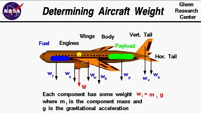
Types of aircraft weights are the following:
1)Manufatures empty weight:
-It includes the weight of aircraft of the entire flight with its intergal working parts,but excludes baggage ,passenger and fuels.
2)zero fuel weight:
-It includes total weight of aeroplanes including unuseable fuels but excludes total weight of useable fuel at board.
3)Payload:
-It is load carrying capacity of an aircraft which includes passenger ,cargo and fuels,But if it is in the case of cargo flight it determines the total load of logistics weight of the container which it needs to transport.
4)Maximum take off weight:
-This is the maximum weight at which the aircraft would be made to takeoff .
5)Regulated take off weight:
-Depending on different factors (flap setting,altitude,lenght of runway),RTOW varies for each take off,but can never be high for MTOW.
6)Maximum landing weight:
-It is maximum weight at which an aircraft is permitted to land.
7)Maximum Ramp weight:
-It is the maximum weight used for manuevering (towing) aircraft on the ground.
-Listed below are the types of aircraft with its weight:
Category MTOW(kg) MLW(tons)
Boeing 747-8F 447,700 346.091
Airbus A380-800 575,000 394
Concorde 185,000 111.1
Antonov An225 640,000 91.7
Vickers VC10 152,000 151.9
Fokker 100 46,000 39.95
Embraer 175(19) 37,500 32.8
Avro RJ-85 42,000 36.47
Tupolev Tu-154M 104,000 80
Boeing 777-300 299,370 237.683
--------------------------------------------------------------------------------------------------------------------
2)Difference between ground speed and Air speed:
*Ground speed:
-They are the airplane speed which is related to the ground.
-They are the speed which determines how fast the airplane will reach the detination.
-They are the calculated by summing up the airspeed and windspeed.
*Air speed:
-It refers to the speed which is relative to air it is flying in.
-They determine whether there is enough airflow around an aircraft to make it lift.
-They are independent of ground speed.
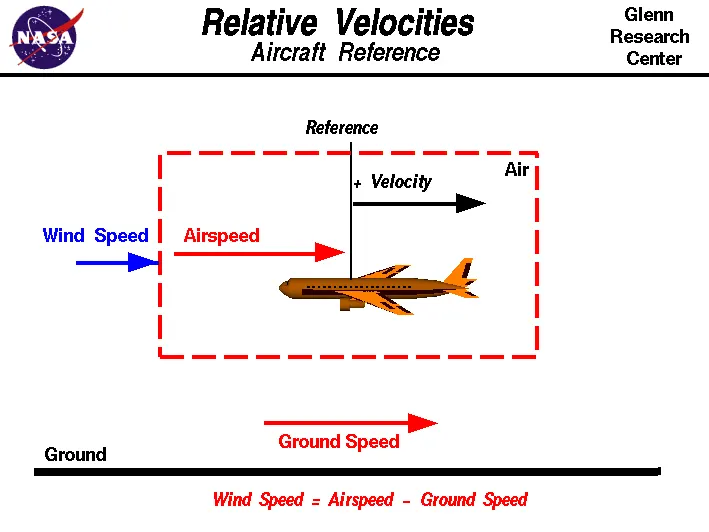
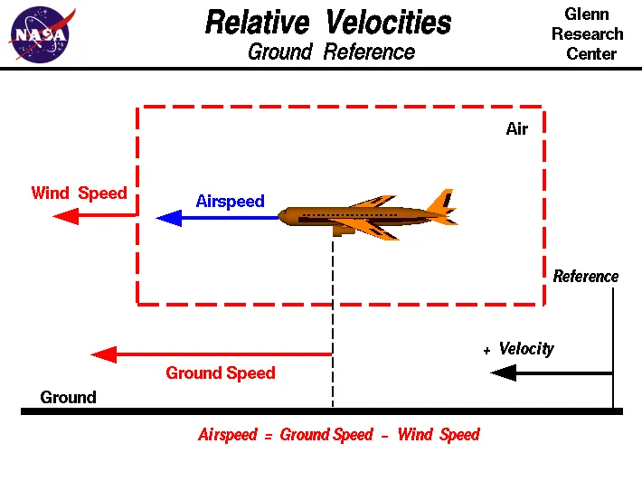
-The above two daigram relative velocity with respect to aircraft reference and ground reference.
-Here wind speed is the vector difference between ground and air speed.On a perfect still day the wind speed is zero and it is equal to the ground speed.
-If the measured air speed is greater than the observed ground speed the wind speed becomes positive.
--------------------------------------------------------------------------------------------------------------------
3)Why it is not recommended to use aircraft engines to move it on the gorund at airport:
-Generally most of the airplane can move itself in reverse manner by making use of reverse thrust technology.But in most of the practical it is not possible because when airplanes start using reverse thrust it will consume lot of fuels as well as causes lot of noise and also hazardous for the people working near by.
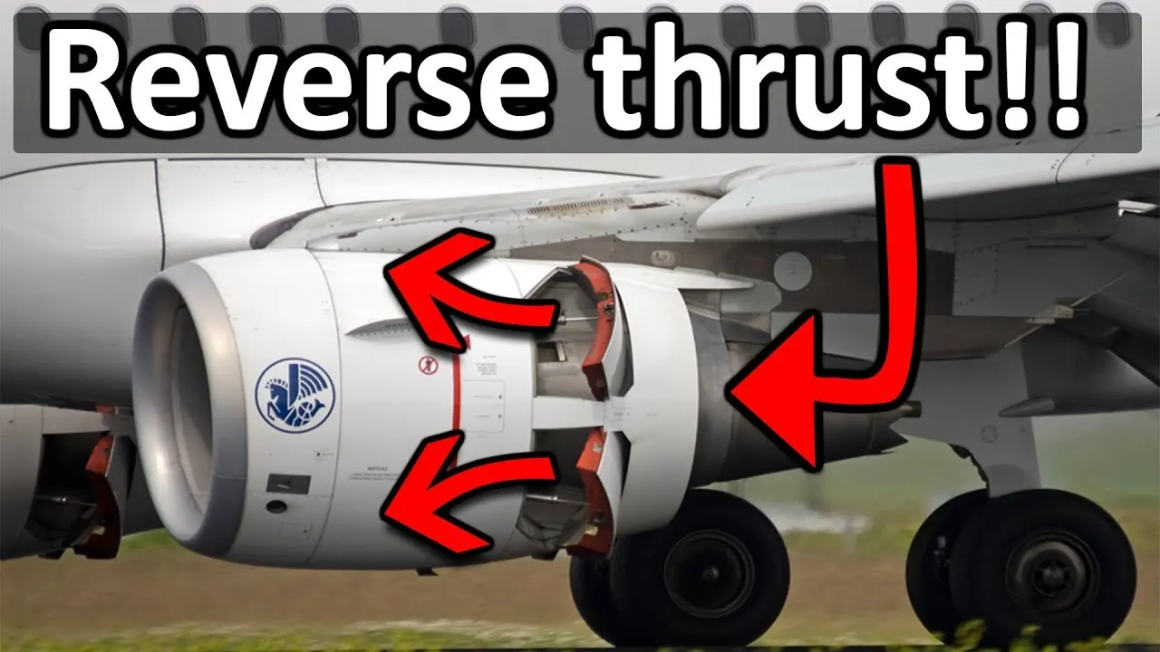
-The another for not using reverse thrust is that the jet blast can cause damage to terminal buildings or its equipments.Since the engine is also close to the ground it will blow off the sand and debreis forward and sucks it to the engine and causes damage to it.
-To solve this kind of issue we use a towing vehicle which helps to tow the vehicle in reverse dierection and it eill be tugged until it reaches a safe place and from there onwards airplane will move by itself for further take off.
4):- How an aircraft is pushed to runway when its ready to take off?
ANS:
Large aircraft cannot be moved by hand and must have a tractor or tug. Pushback tractors use a low profile design to fit under the aircraft nose. For sufficient traction the tractor must be heavy, and most models can have extra ballast added. A typical tractor for large aircraft weighs up to 54 tonnes (59.5 short tons; 53.1 long tons; 119,000 pounds) and has a drawbar pull of 334 kN (75,000 lbf). Often the driver's cabin can be raised for increased visibility when reversing and lowered to fit under aircraft. There are two types of pushback tractors: conventional and towbarless (TBL).
Conventional tugs use a tow bar to connect the tug to the nose landing gear of the aircraft. The tow bar is fixed laterally at the nose landing gear, but may move slightly vertically for height adjustment. At the end that attaches to the tug, the tow bar may pivot freely laterally and vertically. In this manner the tow bar acts as a large lever to rotate the nose landing gear. Each aircraft type has a unique tow fitting so the towbar also acts as an adapter between the standard-sized tow pin on the tug and the type-specific fitting on the aircraft's landing gear. The tow bar must be long enough to place the tug far away enough to avoid hitting the aircraft and to provide sufficient leverage to facilitate turns. On heavy tow bars for large aircraft the towbar rides on its own wheels when not connected to an aircraft. The wheels are attached to a hydraulic jacking mechanism which can lift the towbar to the correct height to mate to both the airplane and the tug, and once this is accomplished the same mechanism is used in reverse to raise the tow bar wheels from the ground during the pushback process. The tow bar can be connected at the front or the rear of the tractor, depending on whether the aircraft will be pushed or pulled. The towbar has a shear pin which prevents the aircraft from being mishandled by the tug; when overstressed the shear pin will snap, disconnecting the bar from the nose gear to prevent damage to the aircraft and tug.
5)To learn about take off power,tyre design,rolling resistance,tyre pressure,brake froce when landing?
-Take off is the phase of the flight in which an aeroplane leaves ground and becomes airbone.For lighter aircraft full power is given durong take off where as on the other hand large cargo carriers aircraft make use of less power during take off inorder to inrease the life span of engine,reduce maintenance cost ,reduce engine heat and also for a smooth take off flight.
-The forces involved during take off are the following:
T=Thrust froce pushes the aircraft in forward dierection on the runway.
D=Drag force resist the forward motion of the aircraft.
F=Rolling resistance force when wheel comes in contact with the gorund during landing and take off.
-During take off on the runway the imbalance froce will cause an acceleration along the runway and it is given by the formula:
dv/dt=T-D-F/m
-Now when the pilot is ready to take off the aircraft will accelerated to a speed which would be given by aircraft controlling department.Then after take off the flight will be elevated to a certain angle and hieght.then it will be made to stabilies in an equilibrium manner.
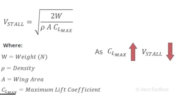
-Here safe speed or rotational speed is defined as Vr which act as a critical factor for determining take off performance.For safety reasons Vr is usually determined as 1.1*Vstall(lowest speed that aircraft can be flown before the air starts to seperate from the wings when the angle of attract becomes too great.
-Vstall can be calculated by using a formula given:
*Tyre design of an aircraft:
-An aircraft tyre are deisgned to withstand extreme heavy loads by absording shocks during and there by providing cushioning effect.
-The number of tires required for an aircraft depends on the total weight of aircraft as the weight needs to be distributed evenly.
-Aircraft tyre are designed to facillitate stability in high crosswind condition,to chanalize the water away for preventing skidding and helps to give a good braking effect.
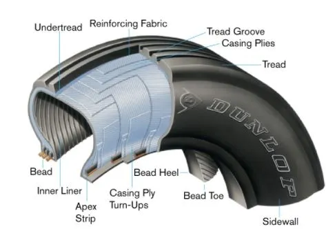
-Aircraft tires are usually inflated by nitrogen air inorder to reduce expansion and contraction from extrerme changes in ambient pressure and tempurature.This type of inert gases will eliminate the possibilty of tire explosion.
-Aircraft tire design are set into an aircraft based on its application and also suffeicient clearance with the ground for allowing tyre growth which happens when centrifugal force is at high speed.
*Rolling Resistance:
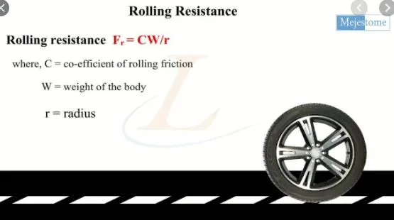
-Rolling resistance or rolling drag is the force resisting the motion when the body rolls on a surface and it is mainly caused by non elasticity that is not all the energy needed for deformation of wheel is recovered when the pressure is removed.
-The rolling resistance equation can be defined by the folowing equation:
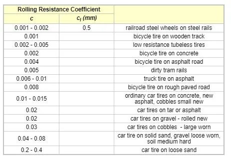
-Usually aircrafts have a very low rolling resistance coeffiecient of 0.06. Some other examples are as follows:
*Tyre Pressure:
-Aircraft tyres are designed to withstand heavy loads and shocks durong landing and take off and also needs to distribute weight evenly.
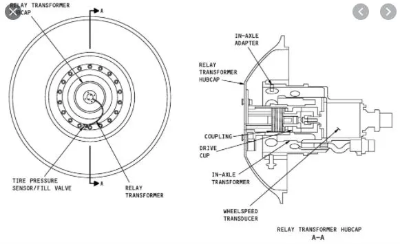
-As per research and testing it is found that aircraft tyres are able to sustain pressure upto 800 psi.Generally to note the tyre pressure of an aircraft a special type of sensors are used,its daigram is given below:
-There are 2 primary parameters which is hazardous to the aircraft tires:
I)Deflation:
Here the tire deflates in a controlled ma-nner with minimum dierect consequence to other system.
II)Explosive breakup:
In this case the tire deflates or bursts in an uncontrolled manner with a probablity of causing damage to other secondary system,which further can cause a major crash landing incidents.
*Brake forces:
-Braking an aircraft is a challenging job for most of the pilots especially during landing in a rainy and cross wind environment.
-Inorder to encounter this kinds of problem pilots usually make use of spoilers and reverse thust method inorder to have a safe landing so that the energy required to apply brakes on tires can be reduced and henceforth they do not skid.
-Now there is method which determines the brake force for aircrafts and they are as follows:
k=1/2mv^2,where m= mass of aircraft and v=velocity of aircraft.A typical commercial landing speed will range between 150 to 165 MPH.And for passenger flight it is about 166 to 172mph.
6. A. calculating the force and power required to push / pull an aircraft by a towing vehicle:
ANS:
The forces required to push/ pull an aircraft by a towing are rolling resistance force and areodynamic drag force. 1) Rolling resistance force:- As we have discussed in part-A 5c. It is the force resisting the motion when a body (such as a ball, tire, or wheel) rolls on a surface. Its governing equation is given as
F = CN
F=C*m*g
where,
Crr= Rolling resistance coefficient m=Mass of the body g= acceleration due to gravity
2)Aerodynamic Drag Force:
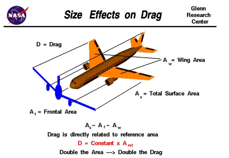
It is the force opposing the motion of the body. The drag coefficient is a common measure in automotive design as it pertains to aerodynamics, Drag is a force that acts parallel to and in the same direction as the airflow. The drag coefficient of an automobile measures the way the automobile passes through the surrounding air. When automobile companies design a new vehicle, they take into consideration the automobile drag coefficient in addition to the other performance characteristics. Aerodynamic drag increases with the square of speed; therefore, it becomes critically important at higher speeds. Reducing the drag coefficient in an automobile improves the performance of the vehicle as it pertains to speed and fuel efficiency. The governing equation of these force is given as following:
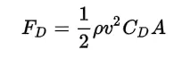
where.
F{D} = dra force
rho = r density of the air
น = flow velocity relative to the object
C{D} = drag coefficient
A = reference area
Calculation:
let us assume that,
Mass of Towing Vehicle= 40,000kg
Mass of aircraft = 155,000kg
Total mass (m)= 40,000+155,000 =195,000kg
Frontal Area of the aircraft (A) =18 m²
Speed of the vehicle (2)=25Kmph
converting it into m/sec
u=25*(1000/3600)=6.9445m/sec
Drag coefficient (Cd) =0.75
Air density (P)=1.225Kg/m³
Calculating Rolling resistance Force (Frr) =Crr*m*g
=0.01*195.000*9.8
= 19.11ON
Calculating Aerodynamic Drag Force (Fd)=0.5*p Cd*A* v^2
=0.5 *1.225 *18* 0.75* (6.9445)2
=398.769N
Therefore the total Force required to push/pull the aircrcraft by the towing vehicle (F) Frr+Fd
=19,110+398.769
=19,508.769 N
Calculating the power (p) =Force*Velocity
= 19508.769* 6.9445
=135.478kW
B. Developing the model for the calculated force and power using Simulink:
Blocks Used:
1) Constant
2) Sum
3) Product
4)Square
5)Display
Model: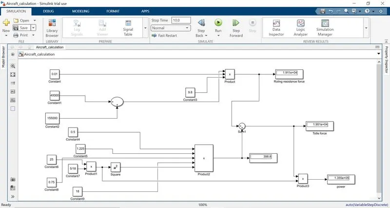
Explaination:
In order to understand the above simulink model we do reverse engineering
• For calculating power we have to multiply both total force(F) and velocity in m/sec for this we have used 'product' block (P-FV).
• For calculating the Total Force(F) we have added both Frr & Fd by using 'Surn' block as shown in the above figure
• To find the value of rolling resistance (Frr) we used product to multiply the values Crr., Total mass(m) & gravity (g) which are to be entered in the 'Constant block.
. Similarly for calculating Drag force(Fd) we have to multiply the velocity in m/sec.Drag coefficient, Frontal area of aircraft(A) and a constant value 0.5 which are to be entered in constant block.
• In order to convert velocity in Kmph to m/sec we have multiplied it with 5/18.
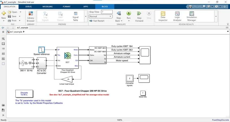
7) A. Design an electric powertrain with type of motor, it’s power rating, and energy requirement to fulfill aircraft towing application in Simulink. Estimate the duty cycle range to control the aircraft speed from zero to highest. Make all required assumptions. Prepare a table of assumed parameters. Draw a block diagram of powertrain.
ANS:
powertrain block diagram:
Based on the calculations done in 6A.
Force required to push/pull the aircraft =19.508 KN
Power required =135.478 kw
Let us assume,
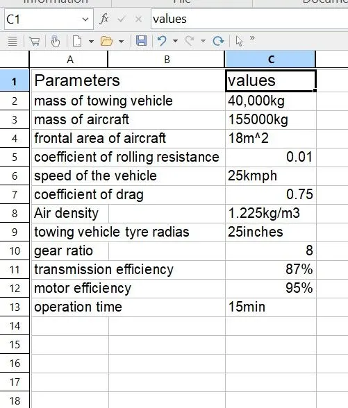
The Radius of the Tyre for the Tug - 25inches =0.635m
Gear ratio=8
Transmission Effeciency (nt) =87%
Motor Efficiency (nm)=95%
then,
Torque required for the wheels (Tw)=Total Force *Radius in meters
=19.508 *0.635
=12.387KNm
Motor Torque-Wheel torque/(Gear ratio'nt)
=12.387/(8 0.87)
=1.778KNm
For nm =95%. The required motor Torque (Tm)= 1.778/0.95 =1.871 kNm
Similarly. The total power required by the motor considering all the efficiencies (Pt) = 135.478/(0.87*0.95)=163.917Kw
Let us assume the towing operation was done for a 15 minutes (0.25Hrs) duration.
Then, Total Energy consumed = 163.917* 0.25=40.98 KWh
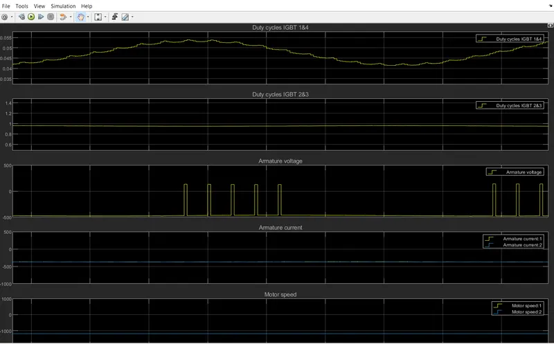
If we consider the battery capacity=220 kw is used by the towing vehicle then. The duty cycle range to control the speed from O to max speed (3m/s) is given as
Duty Cycle (d)= (Required Power)/ (Rated power)= 163.917/220 =0.75
Therefore the controller will be able to provide a duty cycle ranging from 0 to 75% in order to control the towing speed.
DC7 model:
Scope:
B. Also, Design the parameters in excel sheet.
ANS:
Conclusion:
Part:A
1.The total weight of various types of aircrafts.
2.Difference between ground speed and air speed.
3.Aircraft engine power to move it on the ground at Airport.
4.Aircraft is pushed to runway when its ready to take off.
5.Take off power, tyre design, rolling resistance, tyre pressure, brake forces when landing.
Part:B
1.Calculate the force and power required to push / pull an aircraft by a towing vehicle.
2.Design an electric powertrain with type of motor, it’s power rating, and energy requirement to fulfill aircraft towing application in Simulink
B. Also, Design the parameters in excel sheet.
Reference: Google,wikipidia,matlab help.
note: All files is uploaded.