Project-1: Powertrain for aircraft in runways
PART A:
1.
A brief description about these is below:
Manufacturer's empty weight (MEW)
Also called Manufacturer's Weight Empty (MWE) or Licensed Empty Weight
It is the weight of the aircraft "as built" and includes the weight of the structure, power plant, furnishings, installations, systems and other equipment that are considered an integral part of an aircraft.
This excludes any baggage, passengers, or usable fuel2.
Zero-fuel weight (ZFW)
This is the total weight of the airplane and all its contents (including unusable fuel), but excluding the total weight of the usable fuel on board.
As a flight progresses and fuel is consumed, the total weight of the airplane reduces, but the ZFW remains constant.
Maximum zero fuel weight (MZFW) is the maximum weight allowed before usable fuel and other specified usable agents (engine injection fluid, and other consumable propulsion agents) are loaded.
Operating empty weight (OEW) (Roughly equivalent to basic empty weight on light aircraft)
It is the basic weight of an aircraft including the crew, all fluids necessary for operation such as engine oil, engine coolant, water, unusable fuel and all operator items and equipment required for flight but excluding usable fuel and the payload.
It is the carrying capacity of an aircraft. It includes cargo, people, extra fuel. In the case of a commercial airliner, it may refer only to revenue-generating cargo or paying passengers.
Maximum takeoff weight (MTOW)
This is the maximum weight at which the pilot of the aircraft is allowed to attempt to take off3.
Regulated takeoff weight (RTOW)
Depending on different factors (e.g. flap setting, altitude, air temperature, length of runway), RTOW or maximum permissible takeoff weight varies for each takeoff. It can never be higher than MTOW. More information is on this answer.
Maximum landing weight (MLW)
This maximum weight at which an aircraft is permitted to land3.
The following image depicts takeoff weight components.
Maximum ramp weight (MRW)
also called maximum taxi weight (MTW)
the chart for various aircraft weights is guvcen below
| Type | MTOW [kg] | MLW [tonnes] | TOR [m] | LR [m] | ICAO category | FAA category |
|---|---|---|---|---|---|---|
| Airbus A220-100 | 59,000 | 50.80 | 1463 | 1356 | Medium | Large |
| Airbus A220-300 | 65,000 | 57.61 | 1890 | 1494 | Medium | Large |
| Airbus A300-600[14] | 163,000 | 138 | 2324 | 1536 | Heavy | Heavy |
| Airbus A300-600R[14] | 192,000 | 140 | 2385 | 1555 | Heavy | Heavy |
| Airbus A310-200[14] | 142,000 | 123 | 1860 | 1480 | Heavy | Heavy |
| Airbus A310-300[14] | 157,000 | 124 | 2290 | 1490 | Heavy | Heavy |
| Airbus A318[18] | 59,000 | 57.5 | 1375 | 1340 | Medium | Large |
| Airbus A319[18] | 64,000 | 62.5 | 1850 | 1470 | Medium | Large |
| Airbus A320-100[18] | 68,000 | 66 | 1955 | 1490 | Medium | Large |
| Airbus A321-100[18] | 83,000 | 77.8 | 2200 | 1540 | Medium | Large |
| Airbus A330-200[12][13] | 242,000 | 180 | 2220 | 1750 | Heavy | Heavy |
| Airbus A330-300[12][13] | 242,000 | 185 | 2500 | 1750 | Heavy | Heavy |
| Airbus A330-900 | 251,000 | 191 | 3100 | Heavy | Heavy | |
| Airbus A340-200[8][11] | 253,500 | 181 | 2990 | Heavy | Heavy | |
| Airbus A340-300[8][9] | 276,700 | 190 | 3000 | 1926 | Heavy | Heavy |
| Airbus A340-500[8] | 371,950 | 240 | 3050 | 2010 | Heavy | Heavy |
| Airbus A340-600[8] | 367,400 | 256 | 3100 | 2100 | Heavy | Heavy |
| Airbus A350-900 | 270,000 | 175 | 2670 | 1860 | Heavy | Heavy |
| Airbus A350-1000 | 308,000 | 233.5 | Heavy | Heavy | ||
| Airbus A380-800[1][2][3] | 575,000 | 394 | 3100 | 1930 | Heavy | Super |
| Airbus A400M | 141,000 | 122 | 980 | 770 | Heavy | Heavy |
| Antonov An-124-100M | 405,060 | 330 | 2520 | 900 | Heavy | Heavy |
| Antonov An-225 | 640,000 | 591.7 | 3500 | Heavy | Super | |
| ATR 42-500 | 18,600 | 18.3 | 1165 | 1126 | Medium | Small |
| ATR 72-600 | 22,800 | 22.35 | 1333 | 914 | Medium | Large |
| Avro RJ-85 | 42,000 | 36.74 | Medium | Large | ||
| BAe Jetstream 41 | 10,890 | 10.570 | 1493 | 826 | Medium | Small |
| Beechcraft 1900D | 7,765 | 7.605 | 1036 | 853 | Medium | Small |
| Boeing 377 | 67,000 | Medium | Large | |||
| Boeing 707-120B[15] | 117,000 | 86.3 | Medium | Large | ||
| Boeing 707-320B[15] | 151,000 | 97.5 | Heavy | Heavy | ||
| Boeing 707-320C[15] | 151,000 | 112.1 | Heavy | Heavy | ||
| Boeing 717-200BGW | 50,000 | 46.265 | 1950 | Medium | Large | |
| Boeing 717-200HGW | 55,000 | 47.174 | 1950 | Medium | Large | |
| Boeing 720[16] | 104,000 | 79.5 | Medium | Large | ||
| Boeing 720B[16] | 106,000 | 79.5 | Medium | Large | ||
| Boeing 727-100[17] | 72,500 | 62.4 | Medium | Large | ||
| Boeing 727-100C[17] | 72,500 | 62.4 | Medium | Large | ||
| Boeing 727-200[17] | 78,000 | 68.1 | Medium | Large | ||
| Boeing 727-200 Advanced[17] | 84,000 | 70.1 | Medium | Large | ||
| Boeing 737-300 | 63,000 | 51.7 | 1939 | 1396 | Medium | Large |
| Boeing 737-400 | 68,000 | 54.9 | 2540 | 1540 | Medium | Large |
| Boeing 737-500 | 60,000 | 49.9 | 1832 | 1360 | Medium | Large |
| Boeing 737-600 | 66,000 | 54.66 | 1796 | 1340 | Medium | Large |
| Boeing 737-700 | 70,000 | 58.06 | 1921 | 1415 | Medium | Large |
| Boeing 737-800 | 79,000 | 65.32 | 2308 | 1634 | Medium | Large |
| Boeing 737-900 | 85,000 | 66.36 | 2500 | 1704 | Medium | Large |
| Boeing 737-900ER | 85,000 | 71.35 | 2804 | 1829 | Medium | Large |
| Boeing 747-8 | 443,613 | 306.175 | 3100 | Heavy | Heavy | |
| Boeing 747-8F | 447,700 | 346.091 | 3100 | 1800 | Heavy | Heavy |
| Boeing 747-100[7] | 340,200 | 265.300 | Heavy | Heavy | ||
| Boeing 747-200[7] | 377,840 | 285.700 | 3338 | 2109 | Heavy | Heavy |
| Boeing 747-300[7] | 377,840 | 260.320 | 3222 | 1905 | Heavy | Heavy |
| Boeing 747-400 | 396,900 | 295.742 | 3018 | 2179 | Heavy | Heavy |
| Boeing 747-400ER | 412,770 | 295.742 | 3090 | Heavy | Heavy | |
| Boeing 757-200 | 116,000 | 89.9 | 2347 | 1555 | Medium | Large |
| Boeing 757-300 | 124,000 | 101.6 | 2550 | 1750 | Medium | Large |
| Boeing 767-300 | 159,000 | 136.078 | 2713 | 1676 | Heavy | Heavy |
| Boeing 767-300ER | 187,000 | 136.08 | 2713 | 1676 | Heavy | Heavy |
| Boeing 767-400ER | 204,000 | 158.758 | 3414 | Heavy | Heavy | |
| Boeing 777-200ER | 297,550 | 213.00 | 3380 | 1550 | Heavy | Heavy |
| Boeing 777-200LR | 347,450 | 223.168 | 3000 | Heavy | Heavy | |
| Boeing 777-300 | 299,370 | 237.683 | 3380 | Heavy | Heavy | |
| Boeing 777-300ER | 351,800 | 251.29 | 3100 | Heavy | Heavy | |
| Boeing 777F | 347,800 | 260.816 | 2830 | Heavy | Heavy | |
| Boeing 787-8[10] | 228,000 | 172.365 | 3300 | 1695 | Heavy | Heavy |
| Boeing 787-9[10] | 254,000 | 192.777 | 2900 | Heavy | Heavy | |
| Boeing 787-10[10] | 254,000 | 201.849 | Heavy | Heavy | ||
| Bombardier CRJ200 | 23,000 | 21.319 | 1918 | 1479 | Medium | Large |
| Bombardier CRJ700 | 33,000 | 30.39 | 1564 | 1478 | Medium | Large |
| Bombardier CRJ900[21] | 36,500 | 33.345 | 1778 | 1596 | Medium | Large |
| Bombardier Q400 | 28,000 | 28.01 | 1219 | 1295 | Medium | Large |
| Caravelle III | 46,000 | Medium | Large | |||
| Cessna Citation CJ4[26] | 7,761 | 7.103 | 1039 | 896 | Medium | Small |
| Concorde | 185,000 | 111.1 | 3440 | 2220 | Heavy | Heavy |
| Convair 880 | 87,500 | Medium | Large | |||
| de Havilland Comet 1 | 50,000 | Medium | Large | |||
| de Havilland Comet 2 | 54,000 | Medium | Large | |||
| de Havilland Comet 3 | 68,000 | Medium | Large | |||
| de Havilland Comet 4 | 70,700 | Medium | Large | |||
| de Havilland Hercules | 7,000 | Medium | Small | |||
| Douglas DC-4 | 33,000 | Medium | Large | |||
| Douglas DC-6 | 44,000 | Medium | Large | |||
| Douglas DC-6A | 48,600 | Medium | Large | |||
| Douglas DC-6B | 48,500 | Medium | Large | |||
| Douglas DC-7 | 55,000 | Medium | Large | |||
| Douglas DC-8-32 | 140,000 | Heavy | Heavy | |||
| Douglas DC-8-51 | 125,000 | Medium | Large | |||
| Douglas DC-8-61 | 147,000 | Heavy | Heavy | |||
| Embraer 120 Brasilia | 11,500 | 11.25 | 1560 | 1380 | Medium | Small |
| Embraer 170[22] | 36,000 | 32.8 | 1644 | 1274 | Medium | Large |
| Embraer 175[20] | 37,500 | 32.8 | 2244 | 1304 | Medium | Large |
| Embraer 190[19] | 48,000 | 43 | 2056 | 1323 | Medium | Large |
| Embraer ERJ 145 | 22,000 | 19.3 | 2270 | 1380 | Medium | Large |
| Embraer Phenom 100 | 4,800 | 4.43 | 975 | 741 | Light | Small |
| Embraer Phenom 300[25] | 8,150 | 7.65 | 956 | 677 | Medium | Small |
| Fokker 100 | 46,000 | 39.95 | 1621 | 1350 | Medium | Large |
| Handley Page Hermes | 39,000 | Medium | Large | |||
| Hawker Siddeley Trident 2E | 65,000 | Medium | Large | |||
| Ilyushin IL-86 | 208,000 | 175 | Heavy | Heavy | ||
| Ilyushin IL-96-300 | 250,000 | 175 | 2600 | 1980 | Heavy | Heavy |
| Ilyushin Il-96M | 270,000 | 195.04 | 3115 | 2118 | Heavy | Heavy |
| Learjet 75[23] | 9,752 | 8.709 | 1353 | 811 | Medium | Small |
| Lockheed C-5 Galaxy[4][5][6] | 381,000 | 288.417 | 2530 | 1494 | Heavy | Heavy |
| Lockheed L-1011-200 | 211,400 | Heavy | Heavy | |||
| Lockheed L-1011-500 | 231,300 | 166.92 | 2636 | Heavy | Heavy | |
| McDonnell Douglas DC-10 | 256,280 | 183 | 2990 | 1890 | Heavy | Heavy |
| McDonnell Douglas MD-11 | 273,300 | 185 | 2990 | 1890 | Heavy | Heavy |
| McDonnell-Douglas MD-83 | 73,000 | 63.28 | Medium | Large | ||
| McDonnell-Douglas MD-90-30 | 71,000 | 64.41 | 2165 | 1520 | Medium | Large |
| Pilatus PC-24[24] | 8,300 | 7.665 | 893 | 724 | Medium | Small |
| Saab 340 | 13,150 | 12.930 | 1300 | 1030 | Medium | Small |
| Saab 2000 | 22,800 | 21.5 | 1300 | Medium | Large | |
| Scaled Composites Model 351 Stratolaunch | 589,670 | 3660 | Heavy | Super | ||
| Tupolev Tu-154M | 104,000 | 80 | Medium | Large | ||
| Tupolev Tu-204SM | 104,000 | 87.5 | 2250 | Medium | Large | |
| Vickers VC10 | 152,000 | 151.9 | Heavy | Heavy | ||
| Vickers Viscount 800 | 30,400 | Medium | Large |
2. AIR SPEED:
True airspeed is the speed of your aircraft relative to the air it's flying through. As you climb, true airspeed is higher than your indicated airspeed. Pressure decreases with higher altitudes, so for any given true airspeed, as you climb, fewer and fewer air molecules will enter the pitot tube. Because of that, indicated airspeed will be less than true airspeed. In fact, for every thousand feet above sea level, true airspeed is about 2% higher than indicated airspeed. So at 10,000 feet, true airspeed is roughly 20% faster than what you read off your airspeed indicator.
GROUND SPEED:
The movement of your airplane relative to the ground is called groundspeed. It's true airspeed corrected for wind. With a true airspeed of 100 knots and a tailwind of 20 knots, you'd be flying a groundspeed of 120 knots.
If you shot a police radar gun at a plane flying by, you'd be measuring groundspeed of the airplane, assuming the officer was stationary.
3. Why is it not recommended to use aircraft engine power to move it on the ground at Airport
When modern jet engines are operated at rated thrust levels, the exhaust wake can exceed 375 mi/h (325 kn or 603 km/h) immediately aft of the engine exhaust nozzle. This exhaust flow field extends aft in a rapidly expanding cone, with portions of the flow field contacting and extending aft along the pavement surface (fig. 1). Exhaust velocity components are attenuated with increasing distance from the engine exhaust nozzle. However, an airflow of 300 mi/h (260 kn or 483 km/h) can still be present at the empennage, and significant people and equipment hazards will persist hundreds of feet beyond this area. At full power, the exhaust wake speed can typically be 150 mi/h (130 kn or 240 km/h) at 200 ft (61 m) beyond the airplane and 50 to 100 mi/h (43 to 88 kn or 80 to 161 km/h) well beyond this point.
4. How an aircraft is pushed to runway when its ready to take off?
Ready for take-off in ten steps…
- The pilot parks the aircraft in exactly the right place. Usually with the help of an automatic system, but occasionally guided by a marshaller waving two paddles or wands. Dozens of handling personnel are already standing by to perform a whole range of tasks simultaneously.
- As soon as the aircraft is stationary and the engines are switched off, the first priority is to disembark the passengers as quickly as possible. The apron handler places chocks in front of the wheels and connects the ground power. Meanwhile, the passenger bridge manoeuvres up to the door and a belt loader rolls up to the cargo hold. Luggage is unloaded and transferred to the terminal on baggage carts.
- Refuelling begins, usually from a hydrant at the stand. A hose is attached to this from a special vehicle called a dispenser, with the other side connected to the fuel tank in the wing. Read more about refuelling here.
- Now it is time to service the aircraft. The caterer loads new meals and takes away the food waste and used cutlery and crockery. Other activities include draining the lavatories, replacing the headrest covers, removing rubbish and distributing fresh blankets and in-flight magazine.
- A specialist team – or sometimes the crew themselves – cleans the cabin so that the new passengers board a pristine aircraft.
- Meanwhile, specialists from the airline conduct a technical check to make sure that the engines, wings, control surfaces, landing gear, instruments, doors and other equipment are in full working order.
- The aircraft is now ready for baggage to be loaded for the next flight. This is a quick process, on average taking only 10-15 minutes. A little later the passengers start boarding. As soon as they are all in their seats, the door is closed and the pilot informs air-traffic control that the flight is ready for departure.
- The apron handler removes the chocks. A so-called pushback truck reverses the aircraft into taxiing position, pushing it with a towbar attached to the nose-wheel strut. Or, in the most modern versions, by actually lifting the wheel. That speeds up coupling and decoupling.
- The aircraft taxis to the runway to depart at the agreed time.
- The pilot waits for permission to take off from air-traffic control. This is possible once the departure route is clear. As soon as the go-ahead is received, the plane takes to the air at full power
5. TAKE OFF POWER: The amount of power that an engine is allowed to produce for a limited period of time for takeoff. The use of takeoff power is usually limited to 5 min for reciprocating engines and up to 2½ min for gas turbine engines. This may not always be the case. Specifically, with respect to reciprocating engines, it is the brake horsepower developed under standard, sea-level conditions and under the maximum conditions of the crankshaft rotational speed and the engine manifold pressure approved for the normal take-off. It is limited in continuous use to the period of time shown in the approved engine specifications. With respect to gas turbine engines, it is the thrust developed under static conditions at a specified altitude and atmospheric conditions of the rotor shaft rotational speed and gas temperature approved for the normal takeoff. It is limited in continuous use to the period of time shown in the approved engine specifications.
TYRE DESIGN OF AN AIRCRAFT:
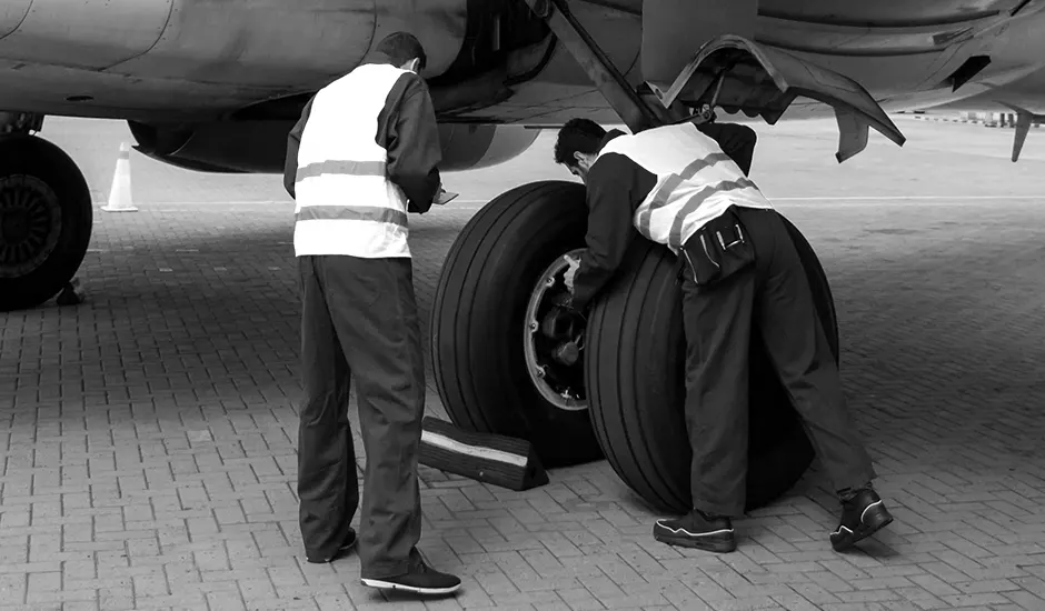
An aircraft tyre is designed to withstand extremely heavy loads while landing, take off, taxing, and parking. The number of wheels required for aircraft increases with the weight of the aircraft, as the weight of the aeroplane needs to be distributed more evenly.
Design and Construction of Aircraft tyre
Carcass plies are used to form the tire. They are sometimes called casing plies. An aircraft tyre is constructed for the purpose it serves.
- They support the weight of an aircraft while it is on the ground.
- It also provides the necessary traction for braking and stopping of an aeroplane.
- Tyre also helps to absorb the shock of landing and provide cushioning the roughness of takeoff, roll-out, and taxi operations.
Unlike an automobile or truck tyre, it does not have to carry a load for a long period of continuous operation. However, an aircraft tyre absorbs the high impact loads of landing, and also it’s operating at high speeds for a short time when required.
Rolling resistance
Rolling resistance is the opposing force a rolling body in motion experiences when it comes in contact with a surface. The energy required for the motion is not fully recoverable and some of it is lost when the pressure is removed [47]. The rolling friction opposes the motion of the car, increasing the energy consumption of the EV. A rubber tire will thereby experience higher rolling resistance on an unpaved road than on a smoother road. Also, sand provides more resistance than a concrete floor. The rolling resistance of a vehicle has a significant impact on its motion and thereby its energy consumption [48]. The coefficient of rolling friction can be expressed
F==Crr N
where F is the rolling resistance force,Crr is the coefficient of rolling resistance, and N is the normal force perpendicular to the surface on which the tire is rolling. Rolling resistance losses are associated with the force necessary to overcome the friction of EV tires.
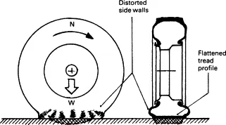
he secondary causes of rolling resistance are air circulation inside the tyre, fan effect of the rotating tyre by the air on the outside and the friction between the tyre and road caused by tread slippage. A typical analysis of tyre rolling resistance losses at high speed can be taken as 90–95% due to internal hysteresis, 2–10% due to friction between the tread and ground, and 1.5–3.5% due to air resistance.
Rolling resistance is influenced by a number of factors as follows:
- a)
-
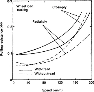
cross-ply tyres have higher rolling resistance than radial ply (Fig. 8.11),
 TYRE PRESSURE OF AN AIRCRAFT
An aircraft tire or tyre is designed to withstand extremely heavy loads for short durations.[1] The number of tires required for aircraft increases with the weight of the aircraft, as the weight of the airplane needs to be distributed more evenly. Aircraft tire tread patterns are designed to facilitate stability in high crosswind conditions, to channel water away to prevent hydroplaning, and for braking effect.
Aircraft tires also include fusible plugs (which are assembled on the inside of the wheels), designed to melt at a certain temperature. Tires often overheat if maximum braking is applied during an aborted takeoff or an emergency landing. The fuses provide a safer failure mode that prevents tire explosions by deflating in a controlled manner, thus minimizing damage to aircraft and objects in the surrounding environment.
Inflation
Each of the twelve Boeing 777-300ER main tires is inflated to 220 psi (15 bar; 1,500 kPa), weighs 120 kg (260 lb), has a diameter of 134 cm (53 in) and is changed every 300 cycles while the brakes are changed every 2000 cycles.[2] Each tire is worth about $5,000.[3] Aircraft tires generally operate at high pressures, up to 200 psi (14 bar; 1,400 kPa) for airliners,[4] and even higher for business jets[citation needed]. The main landing gear on the Concorde was typically inflated to 232 psi (16.0 bar), whilst its tail bumper gear tires were as high as 294 psi (20.3 bar).[5] The high pressure and weight load on the Concorde tyres were a significant factor in the loss of Air France Flight 4590.
Tests of airliner aircraft tires have shown that they are able to sustain pressures of maximum 800 psi (55 bar; 5,500 kPa) before bursting.[citation needed] During the tests the tires have to be filled with water, to prevent the test room being blown apart by the energy that would be released by a gas when the tire bursts.
Aircraft Braking Systems
All modern aircraft are fitted with a braking system to assist in slowing and stopping when on the ground. Brakes are used not only to decelerate during a landing run, but also to hold the aircraft during an engine run-up, and in some cases to steer the aircraft through differential braking. Brakes are fitted to the main landing gear but not generally to the nose or tail wheel.
Brakes work by dissipating energy as heat through the action of friction. An aircraft wheel rotating at speed possesses a large amount of kinetic energy. By contacting the wheel with a semi-metallic or ceramic brake pad, an enormous amount of heat is generated as a result of the friction between the two contacting surfaces.
The large frictional forces generated during braking cause the pads to wear and so careful inspection and maintenance of the system is required to ensure the brakes continue to operate as designed.
Brake Application
Traditionally, brakes are fitted to the upper half of the rudder pedals and are actuated through the pilot applying pressure to the top of each pedal. This toe-brake configuration is widely used and allows the pilot to apply differential braking by varying the pressure applied on each toe brake.
Many smaller light sport aircraft do not make use of toe brakes, preferring to use a simpler single lever mechanism. This lever is usually situated in the cockpit centre console and applies equal braking to all main wheels when engaged. The advantages of a single braking system include reduced complexity and lower part count when compared to toe-brakes. However, differential braking is clearly not possible with a single lever mechanism.
Types of Brakes
Disc Brakes
Disc brakes are the most common braking system in use today and consist of a disc which rotates with the wheel and a stationary brake calliper which actuates onto the disc to affect a braking force. The calliper is the name given to the assembly that contains the brake pads and piston(s). The pads are connected to the piston which actuates under hydraulic pressure applied either through a toe brake or a brake lever in the cockpit.
SINGLE DISC BRAKES
Smaller aircraft typically make use of a single disc sandwiched between two pads and attached to each main landing gear leg. The disc is fixed to the wheel so that it rotates as the wheel rotates. As the pilot applies the brakes, the calliper presses the pads against the disc braking the aircraft.
It is important that the frictional force applied by the callipers is uniform and evenly distributed. A typical braking system is designed with two callipers per disc; one calliper located on either side of the disc. The disc rotates with the wheel but is free to move laterally between the two sets of callipers. As the brakes are applied, the outer calliper moves inward towards the disc, contacting the disc and pushing it onto the inboard stationary calliper. In this way friction is applied evenly on both sides of the disc. When the brakes are released, a spring forces the piston to retract away from the disc, removing the braking action so that the disc is once again free to rotate. This disc brake configuration is called a floating disc brake as the disc is free to “float” laterally between the two callipers.
Figure 2: The disc in a floating disc brake is free to move laterally under braking. An alternate single disc arrangement used on light aircraft is the fixed disc brake arrangement. This works by fixing the disc rigidly to the wheel and allowing the callipers to move laterally as the brake is applied. Similar to the floating arrangement, this ensures that the brake pads apply an even braking force to the disc throughout the braking operation.
MULTIPLE DISC BRAKES
Larger, heavier aircraft with higher landing speeds are unable to extract sufficient braking force out of a single disc and calliper setup. The braking systems for these aircraft are designed with multiple sets of stationary steel discs (stators) sandwiched between copper or bronze rotors which rotate with the wheel. Hydraulic pressure applied to the stack of stators and rotors compresses the plates together, creating a large frictional force which brakes the aircraft.
PART B:
6.
A. With necessary assumptions, calculate the force and power required to push / pull an aircraft by a towing vehicle.
the total force is calaculated by using the formulas as given below
1.Frr=rolling resistance force
Fad=aerodynamic drag force
so ,
condition1:
weight of the aircraft(M)=447700kg
rolling resistance co-eff of tire is=0.004
g=9.8m/s
conddition 2 :
weight of the tug tractor(M)=50000kg
rolling resistance co-eff of towing vehicle is=0.0035
g=9.8m/s
therefor
Frr1=0.004*447700*9.8
Frr1=17549.84N
Frr2=0.0035*50000*9.8
Frr2=1715N
Frr=Frr1+Frr2
Frr=19.26KN = the toatal rolling resistance force
we have to calculate the aerodyanmaic drag force
Fad=1/2rhoACdV^2
velocity of the aircraft towing vehicle=25kmph
air density =1.25kg/m3
frontal area of aircraft=1.8m2
drag co-eff of aircraft=0.025
drag co-eff of tugs tractors=1.15
air drag force of the aircraft=0.5*1.25*20*(6.944^2)*0.25=15.07N
air drag force of tug tractor=0.5*1.25*1.8*(6.944^2)*1.15=62.38N
total aerodyanmic drag force=15.07+62.38 (N) =77.45N
Fad=77.45N
the total force of the aircraft is calculated by
Fte=Frr+Fad
Fte= 19.26+77.45
Fte= 96.71N
the total power of the aircraft is calculated by
P=Fte*V (velocity = from kmph to m/s (25kmph = 6.9m/s)
P= 96.71*6.9
P= 667W
7A :
refering to the values of 6A
tjhe radius of trhe tyre for tug=0.635m
gear ratio=8
transmission n=87%
motor n=95%
torque required by the wheel= total force*radius
= 96.17*0.635
torque=61Nm
motor torque = wheel torque/gear ratio
=61/8
motor torque=7.625Nm
motor torque = 8.026Nm
total powerr required by the motor by consedreding the efficiencies
pt=(667/0.8*0.95)
pt=807W
total energyconsumed=powewr8time
=807*0.25hrs
=201kwh
duty cycle= required powe/rated power
807/220kw
duty cuycle=3.6%
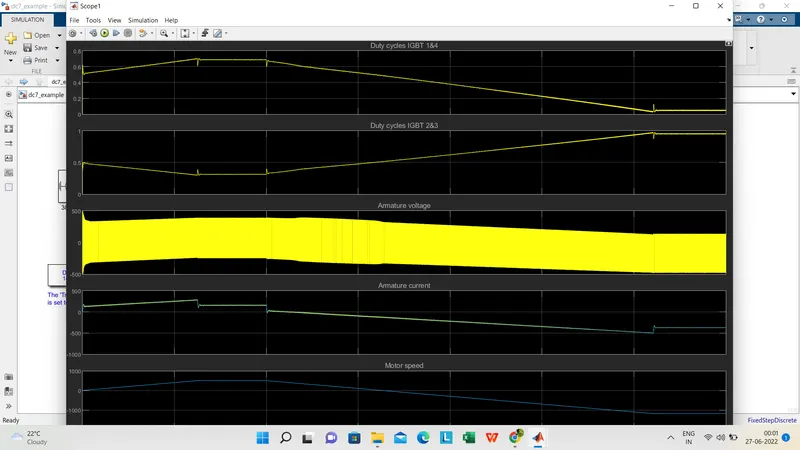
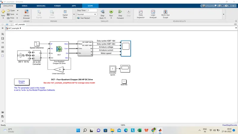
the simulink model of dc_7 has been simulayted