Project-1: Powertrain for aircraft in runways
Part A:
1. Search and list out the total weight of various types of aircraft.
2. Is there any difference between ground speed and airspeed?
3. Why is it not recommended to use aircraft engine power to move it on the ground at Airport?
4. How an aircraft is pushed to runway when its ready to take off?
5. Learn about take off power, tyre design, rolling resistance, tyre pressure, brake forces when landing.
Part B:
6. A. With necessary assumptions, calculate the force and power required to push / pull an aircraft by a towing vehicle.
B. Develop the model for the calculated force and power using Simulink.
7. A. Design an electric powertrain with type of motor, it’s power rating, and energy requirement to fulfill aircraft towing application in Simulink. Estimate the duty cycle range to control the aircraft speed from zero to highest. Make all required assumptions. Prepare a table of assumed parameters. Draw a block diagram of powertrain.
(Hint :DC7 Block)
B. Also, Design the parameters in excel sheet.
Part A:
1. Search and list out the total weight of various types of aircraft.
Maximum Taxi Weight (MTW) means the maximum weight for ground maneuver as limited and/or authorized by airplane strength and airworthiness requirements. (This includes the weight of fuel for taxiing to the takeoff position.).
Maximum Takeoff Weight (MTOW) (also referred to as Brake Release Gross Weight) means the maximum weight for takeoff as limited and/or authorized by airplane strength and airworthiness requirements. This is the maximum weight at the start of the takeoff.
Maximum Landing Weights (MLW) means the maximum weight for landing as limited and/or authorized by airplane strength and airworthiness requirements
Maximum Zero-fuel Weight (MZFW) means the maximum weight permitted before usable fuel and other specified usable fluids are loaded. The MZFW is limited and/or authorized by strength and airworthiness requirements.
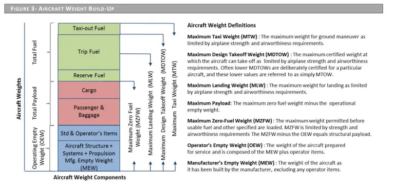
The Operating Empty Weight (OEW) is the sum of the Manufacturer's Empty Weight (MEW), Standard Items (SI), and Operator Items (OI): OEW = MEW + SI + OI
For any aircraft with a defined MZFW, the maximum payload can be calculated as the MZFW minus the OEW (operational empty weight): Max Payload = MZFW – OEW
For any aircraft with a defined MTOW, the maximum MTOW can be calculated as the MZFW plus the reserve & Trip Fuel Capacity: MTOW = MZFW + Reserve Fuel + Trip Fuel
For any aircraft with a defined MTW, the maximum MTW can be calculated as the MTOW plus the
Taxi-out Fuel : MTW = MTOW + Taxi-out Fuel
2. Is there any difference between ground speed and airspeed?
Ground Speed:-
Ground speed is the horizontal speed of an aircraft relative to the ground. An aircraft heading vertically would have a ground speed of zero.
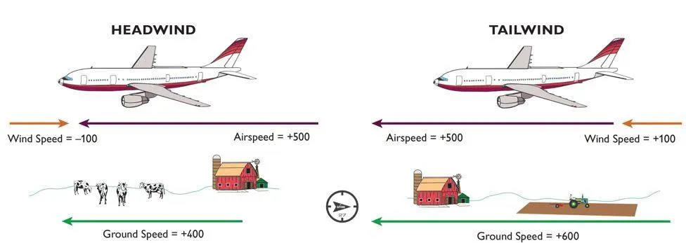
Ground speed can be determined by the vector sum of the aircraft’s true airspeed and the current wind speed and direction a headwind subtracts from the ground speed, while a tailwind adds to it. Winds at other angles to the heading will have components of either headwind as well as a crosswind component.
Wind Speed:-
For a reference point picked on the ground, the air moves relative to the reference point at the wind speed. A positive velocity is defined to be in the direction of the aircraft’s motion. we are neglecting cross winds, which occur perpendicular to the flight path but parallel to the ground, and down crafts, which occur perpendicular to the ground.
Air Speed:-
The important quantity in the generation of lift is the relative velocity between the object and the air, which is called the airspeed. Air Speed cannot be directly measured from a ground position but must be computed from the ground speed and the wind speed. Airspeed is the vector difference between the ground speed and the wind speed.
Air Speed =Ground Speed – Wind speed
- The aircraft usually operates on land as well as in the air and so we need to study the speed difference between in-ground and in the air.
- The ground speed and the air speed usually change based on the wind component.
- If we consider that is no wind component then, ground speed =air speed
- If the wind is blowing in the tail direction of the aircraft then,(air speed>ground speed)so air speed= ground speed+wind component.
- If the wind is blowing in the head direction of the aircraft then,(air speed
- Also, gravity plays a major role in increasing the air crafts speed while it is descending.
- Here the wind speed is the vector difference between ground and airspeed. On a particular day, the wind speed may be zero and it's equal to the ground speed.
- If the measured airspeed is greater than the observed ground speed the wind speed becomes positive.
3)Why is it not recommended to use aircraft engine power to move it on the ground at the Airport?
Aircraft can move using their own engine power all the time on the airport apron and taxiways under their own power to go to words run away and after landing taxi to their assigned gate. But the thrust produced resulting in jet blast might cause damage to the terminal building or equipment Engines close to the ground may also blow sand and debris forward and then suck them into the engine, causing damage to the engine. A pushback is therefore the preferred method to move the aircraft away from the gate. and also it can reduce the cost of fuel. Taxing can save money.
- Effectively a loss of control can happen, especially during high-power engine running. Damage can occur to the aircraft itself, other aircraft nearby, or to airside structures.
- There is a risk of injury to ground support personnel who may be in relatively close proximity to the aircraft.
- It is easier for the truck drivers to see the surroundings better than the pilot sitting in the cockpit with a limited window. The pushback driver knows the airport better than the pilot.
4) How an aircraft is pushed to runway when its ready to take off?
Taxing:
Taxiing is an important process for nearly all airplanes. From small and medium-sized airliners to large wide-body airliners, most airplanes require taxiing while on the runway. Before taking off and after landing, for example, airplanes must taxied
Taxing
Taxiing is simply the process of moving an airplane while it’s on the runway. It occurs after an airplane has landed, and it occurs before an airplane takes off. Airplanes don’t actually fly while on the ground. As a result, the process by which they move on the runway isn’t known as flying; it’s known as taxiing.
How Taxiing Works
There are different ways that airplanes can be taxied. Taxiing is most commonly performed using an airplane’s own propulsion system. For propulsion, most airplanes have either jet engines or propellers. Engaging the propulsion system allows airplanes to move while on the runway.
Some airplanes also have thrust reversers. Thrust reversers live up to their namesake by changing the direction of an airplane’s thrust. In jet-engine airplanes, thrust reversers can assist with taxiing. It essentially allows airplanes to back up while on the runway.
Pilots must still steer airplanes when taxiing them on. Steering is performed using the same control systems as flying an airplane. Pilots can turn the nose wheel or rudder to change the direction in which their airplanes travel while on the runway.
Towing:-
The forward movement of an aircraft, usually with engines off, using the power of a specialised ground vehicle attached to or supporting the nose landing gear. It may occur for the movement of both in service and out of service aircraft. This will affect the promulgation of procedures and the required qualification for those occupying the flight crew seats on the aircraft during the manoeuvre. As part of out of service repositioning of aircraft supervised by maintenance personnel, it may follow the Pushback from a nose-in gate of an empty aircraft with engines off.
PushBack:-
Pushback means the movement of an aircraft from a nose-in parking stand using the power of a specialised ground vehicle attached to or supporting the nose landing gear. It is commonly the second part of a ‘Taxi In Push Out’ (TIPO) procedure at airport terminal gates and will be necessary to depart from all except self manoeuvring parking stands unless the aircraft type is capable of power back and local procedures allow this. Occasionally, a pushback may need to be followed by an engines-running pull forward to a position where local procedures allow aircraft to move forward under their own power, but usually, ground vehicle disconnection will occur after the completion of a pushback.
5)Take off Power:-
The amount of power that an engine is allowed to produce for a limited period of time for takeoff. The use of takeoff power is usually limited to 5 min for reciprocating engines and up to 2½ min for gas turbine engines. This may not always be the case. Specifically, with respect to reciprocating engines, it is the brake horsepower developed under standard, sea-level conditions and under the maximum conditions of the crankshaft rotational speed and the engine manifold pressure approved for the normal take-off. It is limited in continuous use to the period of time shown in the approved engine specifications. With respect to gas turbine engines, it is the thrust developed under static conditions at a specified altitude and atmospheric conditions of the rotor shaft rotational speed and gas temperature approved for the normal takeoff. It is limited in continuous use to the period of time shown in the approved engine specifications.
Tyre Design:-
Design and Construction of Aircraft tyre
Carcass plies are used to form the tire. They are sometimes called casing plies. An aircraft tyre is constructed for the purpose it serves.
They support the weight of an aircraft while it is on the ground.
It also provides the necessary traction for braking and stopping of an aeroplane.
Tyre also helps to absorb the shock of landing and provide cushioning the roughness of takeoff, roll-out, and taxi operations.
Unlike an automobile or truck tyre, it does not have to carry a load for a long period of continuous operation. However, an aircraft tyre absorbs the high impact loads of landing, and also it’s operating at high speeds for a short time when required.
Aircraft Tyre Construction
Let’s go through some technical aspects of the tyre.
Retreading – Retreading is methods of restoring a worn tyre by renewing the tread area or by renewing the tread area plus one or both sidewalls. Repairs are included in the tyre retreading process.
Load Rating – Load rating is the maximum permissible load at a specified inflation pressure.
Ply Rating – Ply Rating is used to identify the maximum recommended load rating and inflation pressure for a specified tyre. It is an index of tyre strength.
Speed Rating – The speed rating is the maximum takeoff speed to which the tyre has been tested.
Skid Depth – Skid depth is the distance between the tread surface and the deepest groove as measured in the mould.
Aircraft tyres must have an approved speed and load rating and have sufficient clearance when retracted through landing gear to allow for tyre growth. Tyre growth is the increase in the size of the tyre due to centrifugal forces at high speed.
Tyre Pressure:-
All the things that operators can do to improve the life of the aviation tire, maintaining good pressure maintenance is right at the top of every list. This article briefly explains why pressure maintenance is so important. For more information check out our useful guide! No other tire has to deal with such high load and extreme speed as an airplane tire. So they need a bit more care than the tires on your car or motorcycle.
Think of the role of the tire as holding the air at a pressure that is able to support the load of the airplane. (Nitrogen is normally used in commercial operations instead of air.)
Like all things aviation, the tire is one part of an assembly which can only work as intended when the parts are used as defined by the airframe and component manufacturers.
Under-inflating the tire or allowing the tire to operate when it is under-inflated will prevent the parts working together as intended.
And it will be the tire that will take the strain. It will deflect more and it will wear more. Harsh operating environments will only make it worse.
Some of the wear will be visible – on the tread and some of the wear will be invisible – inside the structure of the aviation tire.
Visible Wear
Under-inflation will increase the footprint of the aviation tire as it rolls on the ground and will increase the build-up of heat. Heat is no friend to tires on airplanes and the tread will wear out more quickly than it should. On multi-tire landing gear the under-inflated tire will force the other, maybe correctly inflated tires, to take a little bit more of the strain. This will wear those other tires a little more.
Invisible Wear
As extra heat caused by under-inflation builds up in the airplane tire the internal components of the tire might start to separate from each other. A catastrophic failure might result. Component separation in the casing of the tyre will prevent retreading and will increase operating costs. All for a bit of pressure maintenance!
24 Hour Pressure Checks
A carefully thought out pressure maintenance routine will increase the life of the tyre and will reduce the number of wheel changes required.
As all tires can allow a small pressure decrease during normal operations (due to the intense nature of their service life) airplane operators should check tire pressure every 24 hours.
Because putting the right pressure in the tires will always take pressure off the airplane operation
Rolling Resistance:-
The Rolling Friction of Several Airplane Wheels and Tires and the Effect of Rolling Friction on Take-Off
This report presents the results of test made to determine the rolling friction of airplane wheels and tires under various conditions of wheel loading, tire inflation pressure, and ground surface. The effect of wheel-bearing type was also investigated. Six pairs of wheels and tires were tested including two sizes of each of the types designated as standard (high pressure), low pressure, and extra low pressure. The results of calculations intended to show the effect of variations in rolling friction on take-off are also presented.
Part B:
6. A. With necessary assumptions, calculate the force and power required to push/pull an aircraft by a towing vehicle.
B. Develop the model for the calculated force and power using Simulink.
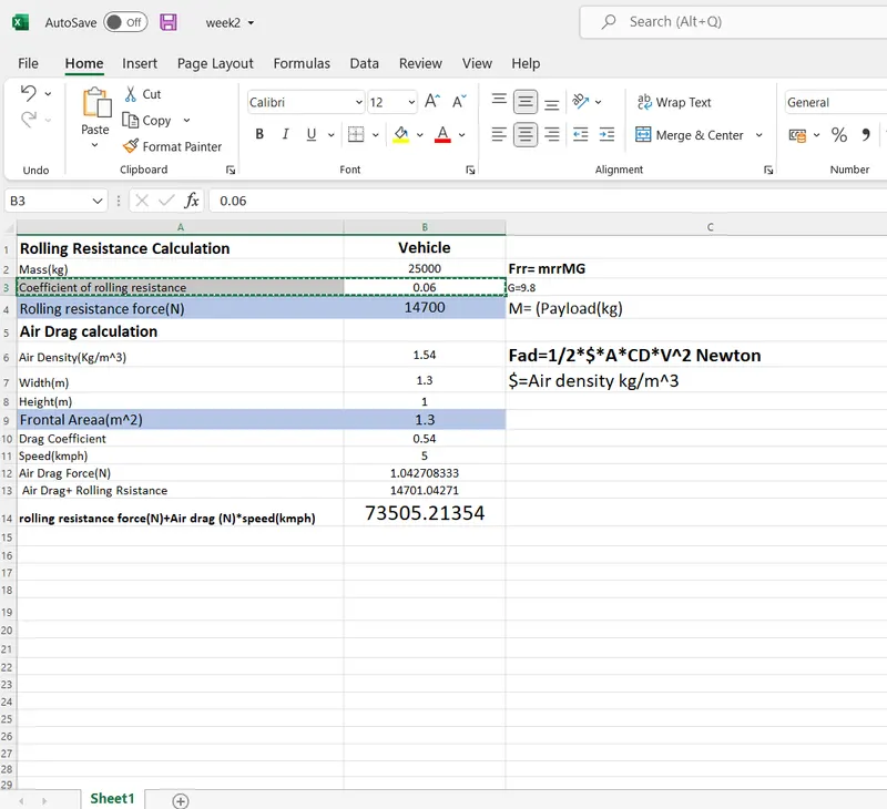
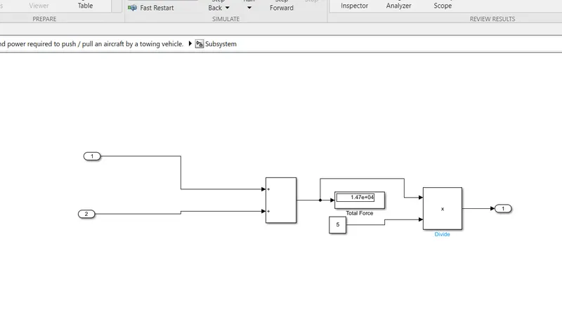
the force and power required to push/pull an aircraft by a towing vehicle. 73kw
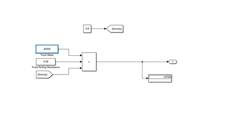
mass = 25000 kg
| Rolling Resistance Calculation |
| Frr= mrrMG | |
| G=9.8 | |
| M= (Payload(kg) | |
|
|
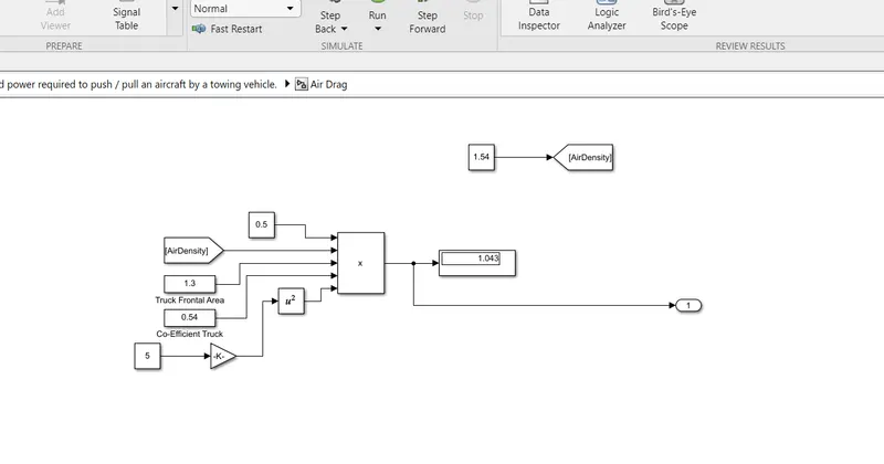
| Fad=1/2*$*A*CD*V^2 Newton | |
| $=Air density kg/m^3 |
B. Develop the model for the calculated force and power using Simulink.
Aim:- The calculated force and power using Simulink
Parameters:-
Constant
Add
Product
From, Goto
Divide
Display
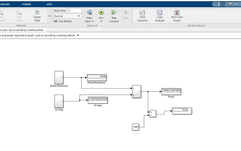
| Rolling Resistance Calculation |
7. A. Design an electric powertrain with type of motor, it’s power rating, and energy requirement to fulfill aircraft towing application in Simulink. Estimate the duty cycle range to control the aircraft speed from zero to highest. Make all required assumptions. Prepare a table of assumed parameters. Draw a block diagram of powertrain.
(Hint :DC7 Block)
B. Also, Design the parameters in excel sheet.
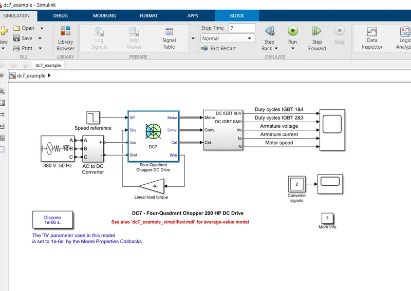
Description
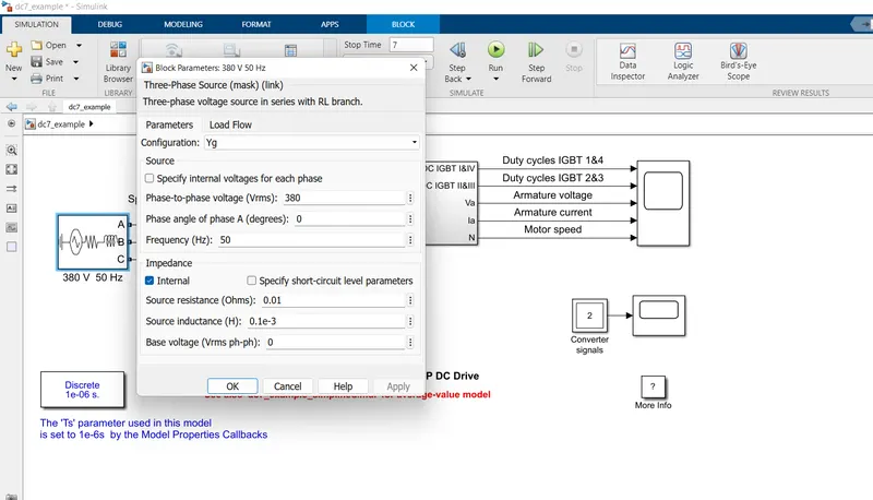
The 200 HP DC motor is separately excited with a constant 150 V DC field voltage source. The armature voltage is provided by an IGBT converter controlled by two PI regulators. The converter is fed by a 515 V DC bus obtained by rectification of a 380 V AC 50 Hz voltage source. In order to limit the DC bus voltage during dynamic braking mode, a braking chopper has been added between the diode rectifier and the DC7 block.
The first regulator is a speed regulator, followed by a current regulator. The speed regulator outputs the armature current reference (in p.u.) used by the current controller in order to obtain the electromagnetic torque needed to reach the desired speed. The speed reference change rate follows acceleration and deceleration ramps in order to avoid sudden reference changes that could cause armature over-current and destabilize the system. The current regulator controls the armature current by computing the appropriate duty ratios of the 5 kHz pulses of the four IGBT devices (Pulse Width Modulation). For proper system behaviour, the instantaneous pulse values of IGBT devices 1 and 4 are opposite to those of IGBT devices 2 and 3. This generates the average armature voltage needed to obtain the desired armature current. In order to limit the amplitude of the current oscillations, a smoothing inductance is placed in series with the armature circuit.
Simulation
Before starting the simulation, set the initial bus voltage to 515 V via the GUI block ('Initial States Setting' button and 'Cbus' variable).
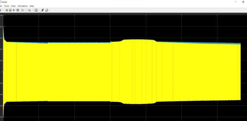
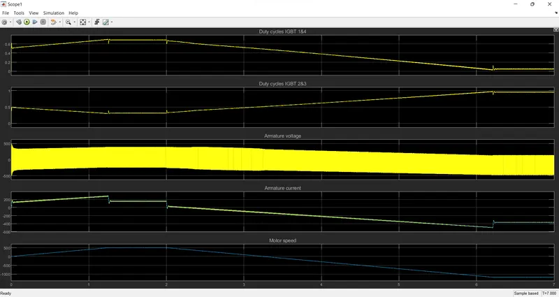
Start the simulation. You can observe the motor armature voltage and current, the four IGBT pulses and the motor speed on the scope. The current and speed references are also shown.
The motor is coupled to a linear load, which means that the mechanical torque of the load is proportional to the speed.
The speed reference is set at 500 rpm at t = 0 s. Observe that the motor speed follows the reference ramp accurately (+400 rpm/s) and reaches steady state around t = 1.3 s.
The armature current follows the current reference very well, with fast response time and small ripples. Notice that the current ripple frequency is 5 kHz.
At t = 2 s, speed reference drops to -1184 rpm. The current reference decreases to reduce the electromagnetic torque and causes the motor to decelerate with the help of the load torque.
At t = 2.2 s, the current reverses in order to produce a braking electromagnetic torque (dynamic braking mode). This causes the DC bus voltage to increase.
At t = 3.25 s, the motor reaches 0 rpm and the load torque reverses and becomes negative. The negative current now produces an accelerating electromagnetic torque to allow the motor to follow the negative speed ramp (-400 rpm/s). At t = 6.3 s, the speed reaches -1184 rpm and stabilizes around its reference.