Week -2
1 Make a Simulink model of Doorbell using solenoid block
Parameter:
Signal builder, Battery, Electrical switch, Solenoid block, Ideal Translational Motion Sensor, solver, scope, Electrical Reference, Mechanical Translational Reference
Connection:
Battery positive (+) is connected to positive of solenoid electrical side and negative (-) is connected to negative of solenoid electrical side and switch is connected in between battery, solenoid positive terminal and solver is connected in between battery, solenoid negative terminal and switch pulse is connected to signal builder by using Simulink-PS
Converter and Ideal Translational Motion Sensor (R) and (C) is connected to solenoid (R) and (C) and Ideal Translational Motion Sensor (P) is connected to scope by using PS-Simulink Converter
Working:
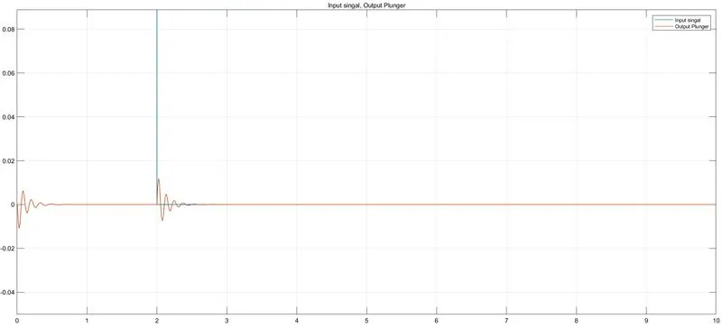
Signal builder is given signal to switch pulse for two seconds after running the simulation for 10 sec and output of plunger see in the scope
Result:
signal starts from 0 to negative still point -0.01 and signal starts going positive direction point 0.01 and signal goes again negative direction and positive directions after slightly it becomes 0 after 2-sec output signal going in positive direction O.O1 and after signal starts going in negative direction -0.01 and it will become zero finally.
2. Use a thermistor to sense the temperature of a heater & turn on or turn off the fan
Parameter:
Thermistor, Controlled Temperature Source, DC Voltage Source, Signal Builder, Current Sensor, solver, Electrical Reference.
Connection:
signal builder is connected to source of the control temperature source by using Simulink-PS Converter and control signal temperature source is connected to the thermistor sensing terminal and thermistor positive and negative terminal is connected to DC source and current sensing is connected in between DC voltage source and thermistor and solver configuration is connected in electrical terminals. and ammeter sensing terminal is connected to the switch by PS-Simulink Converter and switches connected to a scope..
working principal:
given three condition [Temperature source: 20 °C from 0 to 10 seconds, 27 °C from 10 to 30 seconds, 23 °C from 30 to 50 seconds]the signal has been created by using signal builder connect to the control temperature source it is used to convert the signal to the thermal signal given sensing to the thermistor and thermistor changed according to the signal builder inputs so thermistor changes current also changes so current sensor is an sence the current according to the given input of the signal builder through the thermistor.
ammeter sensing terminal is connected to switch. now three given Temperature source[20.c,27.c,23.c] having three different current sensed by an ammeter. before connecting the ammeter sensing terminal to switch
switch use to ON the fan when temperature 25.c OFF otherwise
we have to find what exact current following on the 25.c .so to change the input signal to the signal builder as 25.c now ammeter sensing terminal is connected to scope to find the what exact current flow on the 25.c and that current value given to switch has an threshold value. after finding the threshold value. go back to the normal conditions what we done on first.
now ammeter is connected to switch and switch out is connected to scope to find output.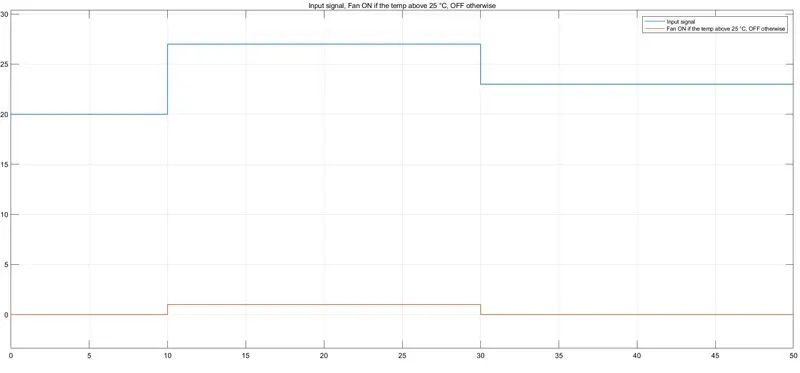
output of the given condication:
Temperature source: 20 °C from 0 to 10 seconds, 27 °C from 10 to 30 seconds, 23 °C from 30 to 50 seconds
Fan conditions: ON if the temperature above 25 °C, OFF otherwise