Project
BAJA ATV model with Continuously Variable Transmission(CVT):
connection:
signal builder is build the throttle input signal for Generic Engine (T) and engine (F) is connected to simple gear used to speed reduction B/W generic engine and CVT( Continuously Variable Transmission) and CVT is connected to the vehicle body
block description:
generic engine:
generic engine for spark-ignition and diesel. Speed-power and speed-torque parameterizations are provided. A throttle physical signal input specifies the normalized engine torque
engine input is a torque given by the signal builder crankshaft is connected to the engine sensor for sensing the RPM of the engine. the engine block is connected to solver
speed threshold is 100rpm and initial velocity 1750rpm
speed vector and torque vector separately created by workspace by using
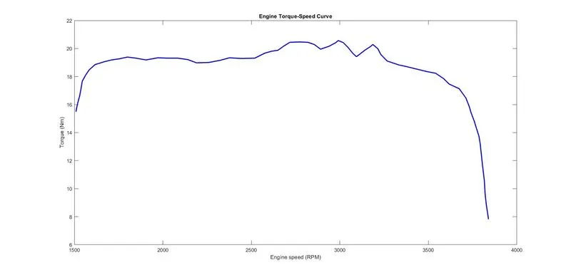
The input of speed and torque is an image file by converting image to date by using file exchange feed to input of engine
Engine maximum 3840 RPM at torque is 7.81nm
the speed sensor is used for sensing for RPM of the engine.
Simple Gear:
Represents a fixed-ratio gear or gearbox and Connections B (base) and F (follower) are mechanical rotational conserving ports simple gear connected B/W CVT and engine
B (base) is an input of gear and F (follower) is an output of gear Base is connected to RPM sensor and follower is an output of CVT.
Follower (F) to base (B) teeth ratio (NF/NB): 12
Continuously Variable Transmission(CVT):
Parameters:
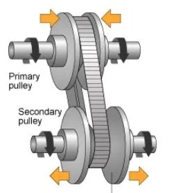
CVT is consists of a primary pulley and the secondary pulley, belt, and variator.
description:
variator which is connected to the primary pulley goes outward and variator of the secondary pulley moves inward is called the speed reduction (Rp<Rs)
variator which is connected to the Secondary pulley goes outward and the variator of the Primary pulley moves inward is called the speed Overdrive (Rp>Rs)
modeling in simscape:
input shaft inertia and output shaft inertia represent a primary pulley and secondary pulley
specify the gear ratio using the variable-ratio gear block. and two sensors are connected to B/W primary pulley and secondary pulley for sensing the RPM of the primary and secondary pulley.
variable-ratio gear is connected to signal builder
Continuously Variable Transmission(CVT) is connected to Vehicle Body.
Vehicle Body:
Parameters:
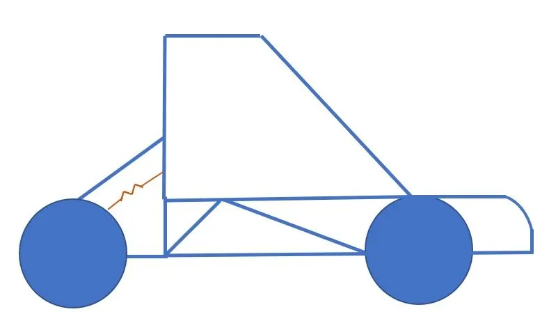
Vehicle Body, Inclination, Double-Shoe Brake, Wind Velocity, four Wheel and Axle blocks.
connection:
Two-wheel and axle(N) of the left rear and right rear are connected to the (Nr) Rear axle normal force of the vehicle body
Two-wheel and axle(N) of the left front and right Front are connected to the (Nf) front axle normal force of the vehicle body
vehicle body of Horizontal motion (H) is connected to all four-wheel of the Hub(H)
vehicle body W is connected to wind velocity and vehicle body of V is connected to the scope
vehicle body mass is 250KG and Gravitational acceleration:9.81m/s^2
Wheel and Axle blocks are Rated vertical load:2060N and Peak longitudinal force at rated load:1260N and Slip at peak force at rated load (percent): 5 and Velocity threshold:0.1m/s.
CVT model Result:
Engine speed output of RPM sensor:
speed threshold is 100rpm and initial velocity 1750rpm
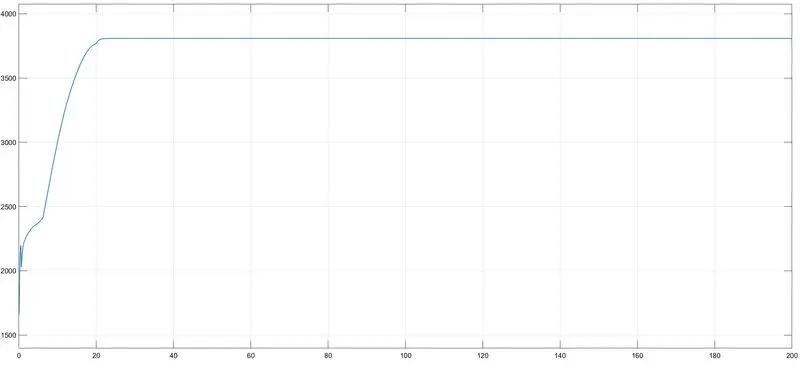
Initial start at 1750rpm and gradually increase at certain point it goes constant RPM because of maximum RPM of the engine is 3840 rpm that why it goes constant
initial torque will be high. because of that starting Rpm will be increasing suddenly and it will increase gradually.
Velocity,distance, throttle and brake output result:
Simple gear = Follower (F) to base (B) teeth ratio (NF/NB): 12
Throttle input (0 to 20) is 0.5 and after 20sec 0.5 to 0.6 .
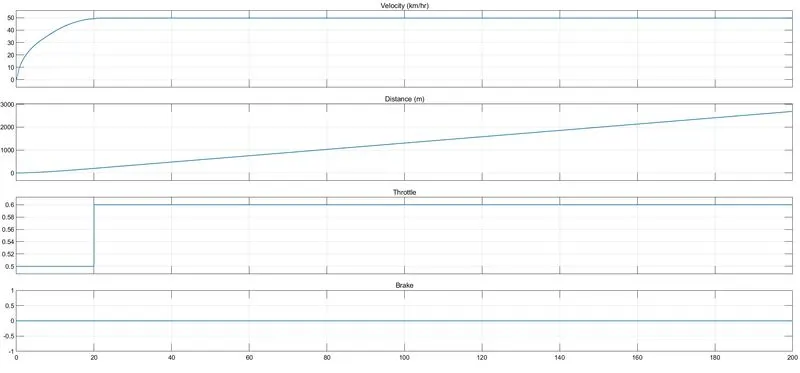
when throttle input is given to the engine 0.5 to 0.6 after 20 sec when throttle input is increased 0.5 to 0.6 and velocity also gradually increases at a certain value
throttle input is increased velocity also increases.
CVT Shaft Speed output result:
Follower (F) to base (B) teeth ratio (NF/NB): 12
Throttle input (0 to 20) is 0.5 and after 20sec 0.5 to 0.6
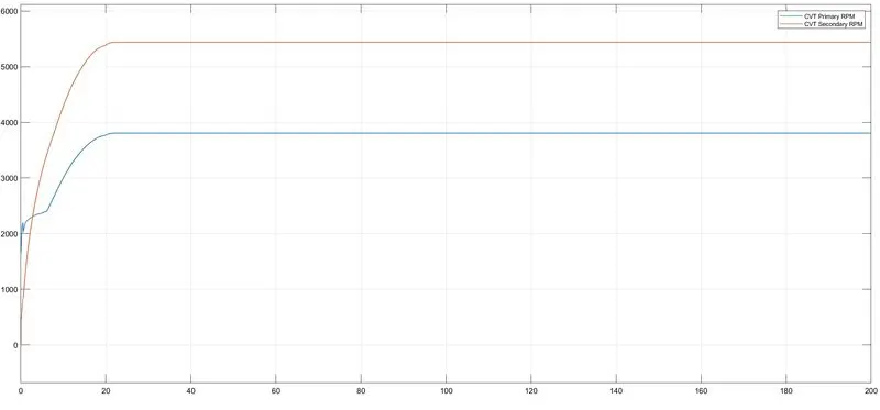
primary and secondary rpm sensing output are connected to the primary and secondary pulley of CVT and output of two signal are the speed of the CVT
primary RPM is always greater than secondary RPM and primary RPM is maximum output of the engine
Primary RPM is 3806.01 and output to the secandry RPM is 5446.92
CVT model_dashboard:
Note:
Initial condition to run the simulation
Brake input=0
Throttle input=0.6
throttle input is given to Generic Engine. velocity and engine RPM is increased by throttle input is increase gradually
when simple gear ratio is increase (10-12) speed of engine and velocity of the engine is decrease.
Output of the engine RPM in scope:
Brake input=0
Throttle input=0.6
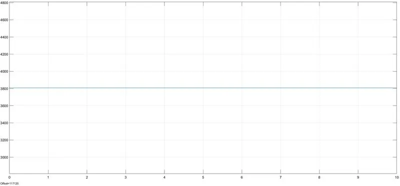
the output of engine RPM =3807.93
Simple gear= Follower (F) to base (B) teeth ratio (NF/NB): 12.
Velocity, distance, throttle, and brake output result:
Input is throttle and brake
output is velocity(km/hr)
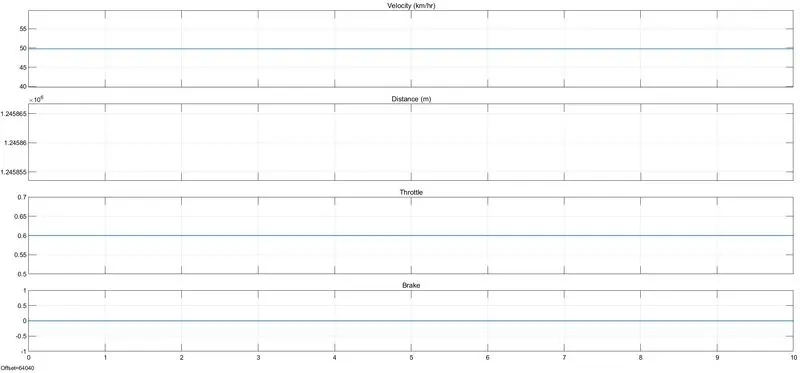
throttle input is increase and velocity also increased and distance also same and brake input is zero
throttle input= 0.6 and the velocity (km/hr)=50.
CVT Shaft Speed output result:
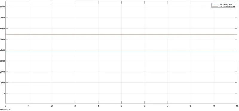
primary RPM is always greater than secondary RPM and primary RPM is maximum output of the engine power
primary RPM=3806.07 and secondary RPM=5446.92
CVT RATIO_RPM:
1-D Lookup Table is connected between engine sensor and CVT and plotted a speed vector and torque vector
in input
given data is a speed vector and torque vector saved in the workspace as an excel file
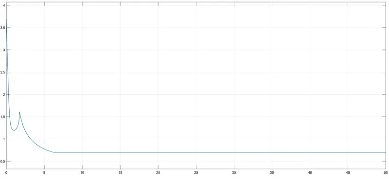
speed vector is plotted on X and torque vector is plotted on Y.
Velocity, distance, throttle, and brake output result:
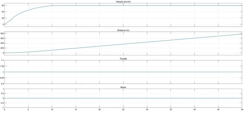
throttle input is a 1 and brake input is =0 and distance is gradually increasing
when run the model as per the lookup table when velocity is gradually increasing a certain point after 10 sec
it goes a constant value of 60km/hr at 10 sec.
comparison of engine RPM and primary RPM, secondary RPM:
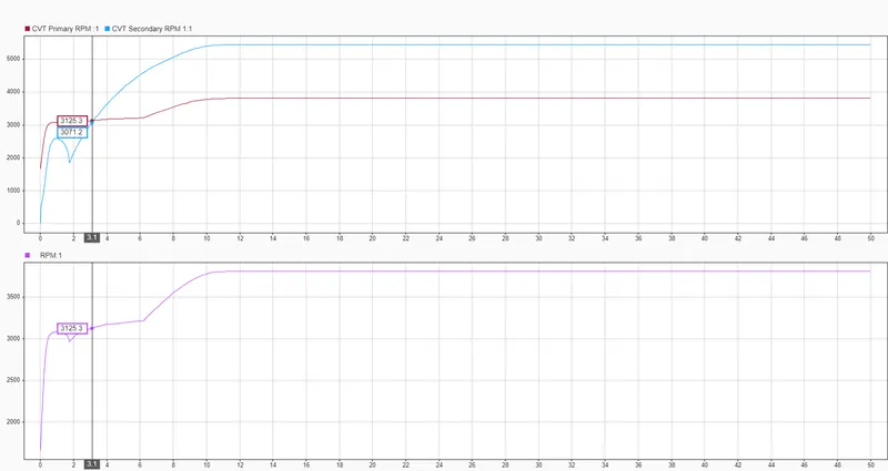
Engine RPM and CVT primary RPM are equal values. at certain points, engine RPM and primary RPM, and secondary RPM reached maximum
CVT MODEL DASHBOARD _MAPPED
CLOSED-LOOP
The closed-loop of the vehicle body velocity is connected to the feedback of the ps lookup table and connected to CVT variable gear ratio as input for the vehicle performances
run the model as INF.changing the throttle input velocity also changes.
Throttle input and velocity :
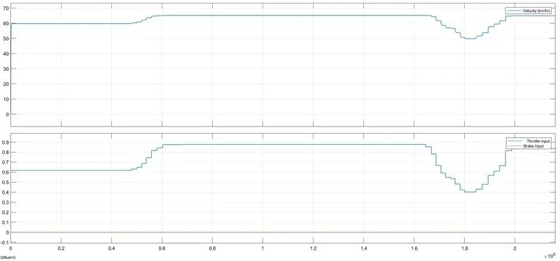
velocity is increasing suddenly from 0 to 60 in throttle input is 0.6. after increasing the throttle different values and speed also changes as per throttle responses.