Project-1: Powertrain for aircraft in runways
1.Search and list out the total weight of various types of aircrafts.
MTOW = Maximum take-off weight, MLW = Maximum landing weight, TOR = Take-off run
|
Type |
MTOW [kg] |
MLW [tonnes] |
TOR [m] |
LR [m] |
|
640,000 |
591.7 |
3500 |
||
|
589,670 |
3660 |
|||
|
575,000 |
394 |
3100 |
1930 |
|
|
447,700 |
346.091 |
3100 |
1800 |
|
|
443,613 |
306.175 |
3100 |
||
|
412,770 |
295.742 |
3090 |
||
|
Antonov An-124-100M |
405,060 |
330 |
2520 |
900 |
|
396,900 |
295.742 |
3018 |
2179 |
|
|
381,000 |
288.417 |
2530 |
1494 |
|
|
377,840 |
285.700 |
3338 |
2109 |
|
|
377,840 |
260.320 |
3222 |
1905 |
|
|
371,950 |
240 |
3050 |
2010 |
|
|
367,400 |
256 |
3100 |
2100 |
|
|
347,800 |
260.816 |
2830 |
||
|
351,800 |
251.29 |
3100 |
||
|
347,450 |
223.168 |
3000 |
||
|
340,200 |
265.300 |
|||
|
308,000 |
233.5 |
|||
|
299,370 |
237.683 |
3380 |
||
|
297,550 |
213.00 |
3380 |
1550 |
|
|
276,700 |
190 |
3000 |
1926 |
|
|
273,300 |
185 |
2990 |
1890 |
|
|
270,000 |
175 |
2670 |
1860 |
|
|
270,000 |
195.04 |
3115 |
2118 |
|
|
256,280 |
183 |
2990 |
1890 |
|
|
254,000 |
192.777 |
2900 |
||
|
254,000 |
201.849 |
|||
|
253,500 |
181 |
2990 |
||
|
251,000 |
191 |
3100 |
||
|
250,000 |
175 |
2600 |
1980 |
|
|
242,000 |
185 |
2500 |
1750 |
|
|
242,000 |
180 |
2220 |
1750 |
|
|
231,300 |
166.92 |
2636 |
||
|
228,000 |
172.365 |
3300 |
1695 |
|
|
211,400 |
||||
|
208,000 |
175 |
|||
|
204,000 |
158.758 |
3414 |
||
|
192,000 |
140 |
2385 |
1555 |
|
|
187,000 |
136.08 |
2713 |
1676 |
|
|
185,000 |
111.1 |
3440 |
2220 |
|
|
163,000 |
138 |
2324 |
1536 |
|
|
159,000 |
136.078 |
2713 |
1676 |
|
|
157,000 |
124 |
2290 |
1490 |
|
|
152,000 |
151.9 |
|||
|
151,000 |
97.5 |
|||
|
151,000 |
112.1 |
|||
|
147,000 |
||||
|
142,000 |
123 |
1860 |
1480 |
|
|
141,000 |
122 |
980 |
770 |
|
|
140,000 |
||||
|
125,000 |
||||
|
124,000 |
101.6 |
2550 |
1750 |
|
|
117,000 |
86.3 |
|||
|
116,000 |
89.9 |
2347 |
1555 |
|
|
106,000 |
79.5 |
|||
|
104,000 |
79.5 |
|||
|
104,000 |
80 |
|||
|
104,000 |
87.5 |
2250 |
||
|
87,500 |
||||
|
85,000 |
66.36 |
2500 |
1704 |
|
|
85,000 |
71.35 |
2804 |
1829 |
|
|
84,000 |
70.1 |
|||
|
Airbus A321-100[18] |
83,000 |
77.8 |
2200 |
1540 |
|
79,000 |
65.32 |
2308 |
1634 |
|
|
78,000 |
68.1 |
|||
|
73,000 |
63.28 |
|||
|
72,500 |
62.4 |
|||
|
72,500 |
62.4 |
|||
|
71,000 |
64.41 |
2165 |
1520 |
|
|
70,700 |
||||
|
70,000 |
58.06 |
1921 |
1415 |
|
|
Airbus A320-100[18] |
68,000 |
66 |
1955 |
1490 |
|
68,000 |
54.9 |
2540 |
1540 |
|
|
68,000 |
||||
|
67,000 |
||||
|
66,000 |
54.66 |
1796 |
1340 |
|
|
65,000 |
57.61 |
1890 |
1494 |
|
|
65,000 |
||||
|
64,000 |
62.5 |
1850 |
1470 |
|
|
63,000 |
51.7 |
1939 |
1396 |
|
|
60,000 |
49.9 |
1832 |
1360 |
|
|
59,000 |
50.80 |
1463 |
1356 |
|
|
59,000 |
57.5 |
1375 |
1340 |
|
|
55,000 |
47.174 |
1950 |
||
|
55,000 |
||||
|
54,000 |
||||
|
50,000 |
46.265 |
1950 |
||
|
50,000 |
||||
|
48,600 |
||||
|
48,500 |
||||
|
48,000 |
43 |
2056 |
1323 |
|
|
46,000 |
||||
|
46,000 |
39.95 |
1621 |
1350 |
|
|
44,000 |
||||
|
42,000 |
36.74 |
|||
|
39,000 |
||||
|
37,500 |
32.8 |
2244 |
1304 |
|
|
36,500 |
33.345 |
1778 |
1596 |
|
|
36,000 |
32.8 |
1644 |
1274 |
|
|
33,000 |
30.39 |
1564 |
1478 |
|
|
33,000 |
||||
|
30,400 |
||||
|
28,000 |
28.01 |
1219 |
1295 |
|
|
23,000 |
21.319 |
1918 |
1479 |
|
|
22,800 |
22.35 |
1333 |
914 |
|
|
22,800 |
21.5 |
1300 |
||
|
22,000 |
19.3 |
2270 |
1380 |
|
|
18,600 |
18.3 |
1165 |
1126 |
|
|
13,150 |
12.930 |
1300 |
1030 |
|
|
11,500 |
11.25 |
1560 |
1380 |
|
|
10,890 |
10.570 |
1493 |
826 |
|
|
9,752 |
8.709 |
1353 |
811 |
|
|
8,300 |
7.665 |
893 |
724 |
|
|
8,150 |
7.65 |
956 |
677 |
|
|
7,765 |
7.605 |
1036 |
853 |
|
|
7,761 |
7.103 |
1039 |
896 |
|
|
7,000 |
||||
|
4,800 |
4.43 |
975 |
741 |
2.Is there any difference between ground speed and air speed?
Airspeed vs. Ground Speed
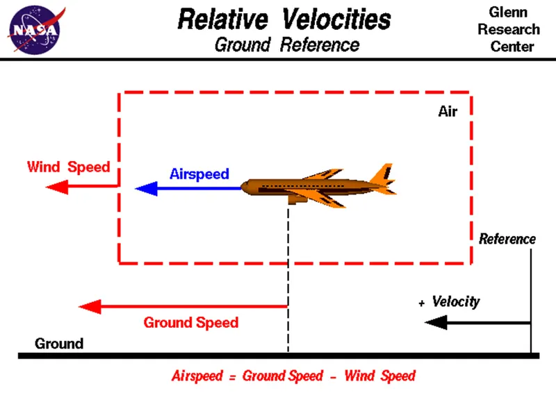
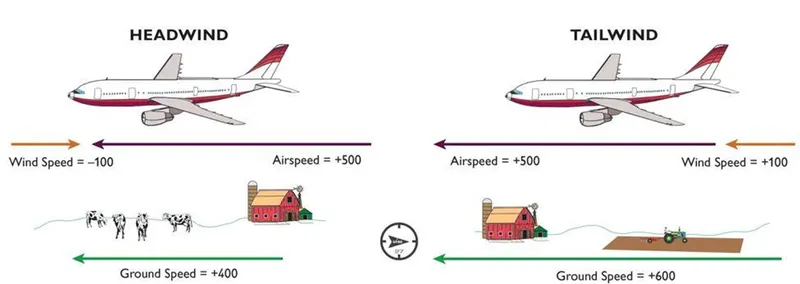
As mentioned above, true airspeed is simply the speed at which an aircraft is moving relative to the air it is flying in. As such, it’s also the speed at which the air is flowing around the aircraft’s wings.
Ground speed, on the other hand, is the aircraft’s speed relative to the ground. One thing that should be noted here is that it’s its horizontal rather than vertical speed – an aircraft climbing completely vertically would have a ground speed of zero.
In other words, while airspeed is what determines whether there is enough airflow around an aircraft to make it fly, ground speed is what determines how fast an aircraft will get to its destination.
DIFFERENCE BETWEEN GROUND SPEED AND AIR SPEED
GROUND SPEED AIR SPEED
Ground speed is the airplanes speed relative to the surface of the earth Air speed is the speed relative to the air it is flying in
Ground speed is what determines how fast an aircraft will get to it destination Airspeed is what determines whether there is enough airflow around an aircraft to make it fly
3.Why is it not recommended to use aircraft engine power to move it on the ground at Airport
Large international airports can be massive places. Denver, Colorado’s main airport, for example, takes up an area of 53 square miles. By comparison, the area of Manhattan is 34 square miles, San Francisco is 47 square miles and Miami is 36 square miles. At some airports like Amsterdam, once you’ve landed you can still have several miles left to taxi until you reach the terminal building. Conversely, some busy airports are so restricted for space that it poses real issues for aircraft getting around on the ground. New York’s JFK is a prime example of this.
he area on which aircraft move on the airfield can broadly be separated into three separate categories. The ramp, or apron, is where the stands are located for aircraft to park. The runways are what the aircraft use to takeoff and land. And the taxiways, which they use to get between the two.
Stands, Taxiways and Runways
At most international airports, the runways are either 45 meters or 60 meters wide and can vary in length. London Heathrow has one of the longest runways in the UK at just under 4 kilometers, or around 2.5 miles. At around 380 tons on landing, runways have to be able to withstand repeated impact from aircraft such as the Airbus A380. They also need to ensure that water drains off quickly when it rains so that it doesn’t become too slippery.
Taxiways, too, can vary in width and load-bearing strength depending on the airfield. Depending on these factors, they are categorized so that pilots know which taxiways they are able to use for their aircraft type. The taxiways at some airports can be particularly tight, especially for bigger aircraft. With a wingspan of more than 60 meters, pilots on the 787 Dreamliner always have to be mindful of their wingtips.
Parking stands can also vary in width and length, depending on the aircraft type they are to accommodate. It is on these stands where aircraft park and are unloaded and loaded between flights. They have to provide electrical power for the aircraft whilst the engines are shut down and also enough area around the aircraft to give the multitude of servicing vehicles space to access the aircraft. At some big airports, when not in use by a bigger aircraft, one stand can be used by two smaller aircraft.
Most Aircraft Can’t Reverse
When you arrive at the gate for your flight, more often than not you’ll get a great view of the nose of the aircraft through the terminal window. If you look closely, you’ll be able to see us pilots preparing the aircraft for departure. Funny enough, we can see you peering out at us too, so if we wave, don’t be embarrassed to wave back.
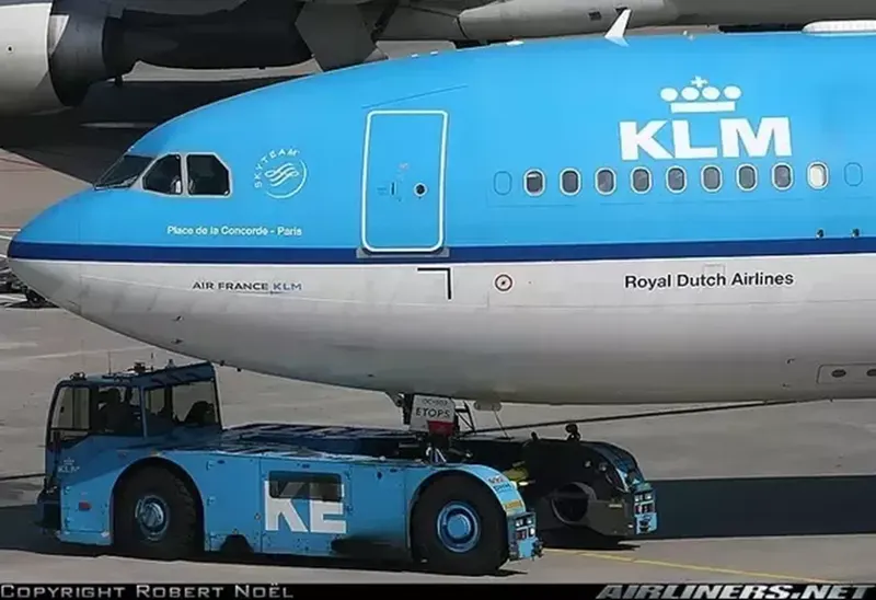
However, the obvious problem with parking facing the terminal is that in order to get to the runway, we need to move backward off the stand first. If this was on your drive at home, you’d just pop your car into reverse, back out onto the street and off you go. Unfortunately, aircraft are unable to do this as they don’t have a reverse gear. In order to get round this problem, we use the assistance of a pushback tug.
ushback Tugs: The Little Engines That Could
For smaller aircraft, the pushback tug doesn’t require a massive amount of power. They utilize the weight of the tug, sometimes up to 60 tons, to ensure that the wheels don’t just spin on the tarmac. “The small ones have enough power to push and tow an aircraft up to a 757,” says Airside MUC, a pushback driver at Munich International Airport. “The functionality is pretty simple. We connect a tow-bar at the aircraft first, then at the tug.”
It takes skill to push an aircraft back using these types of tug. “You have two steering axis here at the nose gear and at the tug where the tow-bar is connected,” he said. “So when you steer right, the nose of the aircraft goes opposite.”
However, with bigger aircraft, tug designers ran into a problem. Even with a 60-ton tug, there isn’t enough weight to stop the tug wheels spinning. To get round this problem, they needed something to weigh the tug down. Something like the weight of a 560-ton A380.
Tow-barless tugs clamp around the nose wheel of the aircraft and lift it up, thus utilizing the weight of the aircraft to provide the traction for its wheels. “We need between 40 and 90 seconds to connect the tug with the aircraft and lift it up,” he added. “The Goldhofer AST-1X is the Godfather of all tugs because at 32 tons, its 16-liter 700 HP engine is enough to push all heavies easily. We use that tug for 767 up to A380.”
Engines Provide the Thrust
Once the tug has disconnected and the engines are running, the pilots call ATC for their clearance to taxi to the departure runway. They will then be issued with a series of taxiways, which will eventually take them to the departure point. At smaller airports, this may just be one taxiway. At larger airfields it could be a number of taxiways, broken up into segments to give way to other aircraft. It’s worth noting that aircraft don’t ‘taxi down the runway’. They taxi on taxiways, hence the name, taxiway. (Sometimes aircraft do have to taxi on the runway, but this is relatively infrequent. So, for the case of this article, I decided to keep it simple.)
If this was your car, you’d put the gear into drive or first gear and press the accelerator. This would inject fuel into the engine and provide power to turn the wheels and off you’d go. However, aircraft wheels aren’t connected to the engines in any way. When the pilots squeeze the thrust levers forwards, the thrust generated from the engines pushes the aircraft forwards. The wheels merely turn under this forward power allowing the aircraft to move.
Steering System
Once moving, pilots need to be able to steer the aircraft around corners. With a wingspan of 60.1 meters, the 787-8 is wider than it is long. The pilot’s eye level is 5.5 meters above the ground, and this creates a 14-meter blind spot ahead of the aircraft. So, accurate taxiing is essential.
This is done through two different sets of controls. Limited steering is possible using the rudder pedals, which sit underneath the pilot’s feet. Unlike in your car, the pedals under our feet have very little to do with acceleration and a lot to do with braking and steering. These primarily control the rudder on the tail (mainly used in crosswind landings) and also control the brakes. However, the main source of steering comes from the nosewheel steering tiller, which can turn the nose wheel up to 70 degrees.
4.How an aircraft is pushed to runway when its ready to take off?
Ready for take-off in ten steps…
The pilot parks the aircraft in exactly the right place. Usually with the help of an automatic system, but occasionally guided by a marshaller waving two paddles or wands. Dozens of handling personnel are already standing by to perform a whole range of tasks simultaneously.
As soon as the aircraft is stationary and the engines are switched off, the first priority is to disembark the passengers as quickly as possible. The apron handler places chocks in front of the wheels and connects the ground power. Meanwhile, the passenger bridge manoeuvres up to the door and a belt loader rolls up to the cargo hold. Luggage is unloaded and transferred to the terminal on baggage carts.
Refuelling begins, usually from a hydrant at the stand. A hose is attached to this from a special vehicle called a dispenser, with the other side connected to the fuel tank in the wing. Read more about refuelling here.
Now it is time to service the aircraft. The caterer loads new meals and takes away the food waste and used cutlery and crockery. Other activities include draining the lavatories, replacing the headrest covers, removing rubbish and distributing fresh blankets and in-flight magazine.
A specialist team – or sometimes the crew themselves – cleans the cabin so that the new passengers board a pristine aircraft.
Meanwhile, specialists from the airline conduct a technical check to make sure that the engines, wings, control surfaces, landing gear, instruments, doors and other equipment are in full working order.
The aircraft is now ready for baggage to be loaded for the next flight. This is a quick process, on average taking only 10-15 minutes. A little later the passengers start boarding. As soon as they are all in their seats, the door is closed and the pilot informs air-traffic control that the flight is ready for departure.
The apron handler removes the chocks. A so-called pushback truck reverses the aircraft into taxiing position, pushing it with a towbar attached to the nose-wheel strut. Or, in the most modern versions, by actually lifting the wheel. That speeds up coupling and decoupling.
The aircraft taxis to the runway to depart at the agreed time.
The pilot waits for permission to take off from air-traffic control. This is possible once the departure route is clear. As soon as the go-ahead is received, the plane takes to the air at full power.
5.Learn about take off power, tyre design, rolling resistance, tyre pressure, brake forces when landing
Why are tyres important in Aircraft?
When it comes to safety, tyres are one of the most important components of aircraft. They help to absorb the shock of landing and provide cushioning. It also provides the necessary traction for braking and stopping of an aircraft.
An aircraft tyre is designed to withstand extremely heavy loads while landing, take off, taxing, and parking. The number of wheels required for aircraft increases with the weight of the aircraft, as the weight of the aeroplane needs to be distributed more evenly.
A Boeing 737NG & 737MAX uses 6 wheels, Boeing 787 uses 10 wheels, Boeing 777 uses 14 wheels and Airbus A380 uses 22 wheels. Aircraft tyres work under extreme conditions, carrying up to 340 tons and accelerating at over 250 km/hour at takeoff, in addition to enduring varied environmental stress when in flight and taxiing.
Design and Construction of Aircraft tyre
Carcass plies are used to form the tire. They are sometimes called casing plies. An aircraft tyre is constructed for the purpose it serves.
- They support the weight of an aircraft while it is on the ground.
- It also provides the necessary traction for braking and stopping of an aeroplane.
- Tyre also helps to absorb the shock of landing and provide cushioning the roughness of takeoff, roll-out, and taxi operations.
Unlike an automobile or truck tyre, it does not have to carry a load for a long period of continuous operation. However, an aircraft tyre absorbs the high impact loads of landing, and also it’s operating at high speeds for a short time when required.
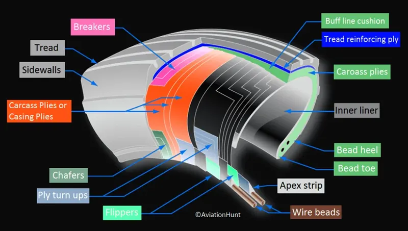
Retreading – Retreading is methods of restoring a worn tyre by renewing the tread area or by renewing the tread area plus one or both sidewalls. Repairs are included in the tyre retreading process.
Load Rating – Load rating is the maximum permissible load at a specified inflation pressure.
Ply Rating – Ply Rating is used to identify the maximum recommended load rating and inflation pressure for a specified tyre. It is an index of tyre strength.
Speed Rating – The speed rating is the maximum takeoff speed to which the tyre has been tested.
Skid Depth – Skid depth is the distance between the tread surface and the deepest groove as measured in the mould.
Aircraft tyres must have an approved speed and load rating and have sufficient clearance when retracted through landing gear to allow for tyre growth. Tyre growth is the increase in the size of the tyre due to centrifugal forces at high speed.
Aircraft tyres may be Tube-type or Tubeless
Tubeless tyres are more advantageous over tube-type. There is no longer the use of tube-type tyre in recent aviation. Nowadays all airliners are using tubeless tyres. Tubeless that are meant to be used without a tube has the word TUBELESS on the sidewall of the tyre.
Aircraft tyres may be Radial or Bias
Almost all airliners are using Radial tyre. Bias is an older design, and it’s mainly used for road vehicles. Radial tyres have the word RADIAL on the sidewall. Radial tires are more expensive than bias-ply tyres. Radial tires are in demand because of their lower life cycle cost and long term value.
Further Read: Aircraft Radial vs Bias Tyre
Are aviation tyres are conductive?
Yes, Today’s tyres are conductive. Aircraft tyres are manufactured with tread rubber with conducting compounds to permit earthing of static charges.
What is the purpose of Chines in aviation tyre
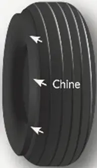
Chines are also called deflectors. Chine tyre used on the nose wheel of aircraft, specially fuselage-mounted jet engines. It diverts runway water away from the engine inlets.
Chines are circumferential protrusions that are moulded into the sidewall of nose tyres that deflect water sideways to help reduce excess water ingestion into the engines. Tyres may have chines on one or both sides, depending on the number of nose tyres on the aircraft
Aircraft Tyre Standards
Each tyre manufacturer produces their own designs of the tyre with different tread patterns, wear patterns, wear limits etc, and in some cases, different names for the same part of the tyre. But all tyres must meet the approved standards before being accepted by the FAA or CAA.
All commercial aircraft tyres approved under FAA Requirement Technical Standard Order (TSO) C62. A TSO is a minimum performance standard for specified materials, parts, and appliances used on civil aircraft.
Rolling resistance
When a loaded wheel and tyre is compelled to roll in a given direction, the tyre carcass at the ground interface will be deflected due to a combination of the vertical load and the forward rolling effect on the tyre carcass (Fig. 8.10). The vertical load tends to flatten the tyre's circular profile at ground level, whereas the forward rolling movement of the wheel will compress and spread the leading contact edge and wall in the region of the tread. At the same time, the trailing edge will tend to reduce its contact pressure and expand as it is progressively freed from the ground reaction. The consequences of the continuous distortion and recovery of the tyre carcass at ground level means that energy is being used in rolling the tyre over the ground and it is not all returned as strain energy as the tyre takes up its original shape. (Note that this has nothing to do with a tractive force being applied to the wheel to propel it forward.) Unfortunately when the carcass is stressed, the strain produced is a function of the stress. On releasing the stress, because the tyre material is not perfectly elastic, the strain lags behind so that the strain for a given value of stress is greater when the stress is decreasing than when it is increasing. Therefore, on removing the stress completely, a residual strain remains. This is known as hysteresis and it is the primary cause of the rolling resistance of the tyre.
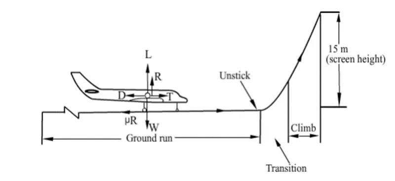
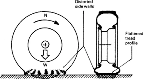
The secondary causes of rolling resistance are air circulation inside the tyre, fan effect of the rotating tyre by the air on the outside and the friction between the tyre and road caused by tread slippage. A typical analysis of tyre rolling resistance losses at high speed can be taken as 90–95% due to internal hysteresis, 2–10% due to friction between the tread and ground, and 1.5–3.5% due to air resistance
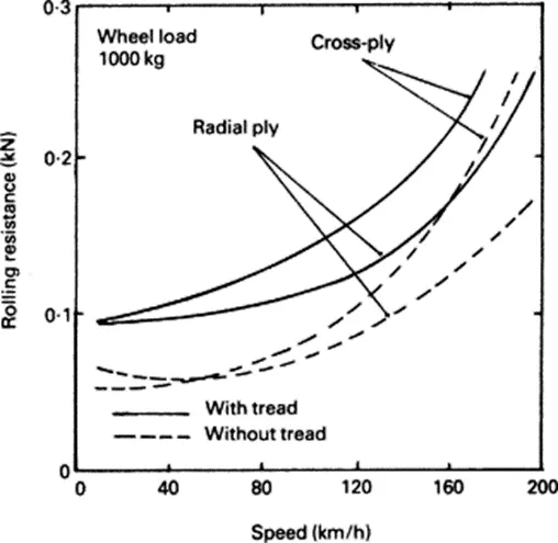
Rolling resistance
Rolling resistance is the opposing force a rolling body in motion experiences when it comes in contact with a surface. The energy required for the motion is not fully recoverable and some of it is lost when the pressure is removed [47]. The rolling friction opposes the motion of the car, increasing the energy consumption of the EV. A rubber tire will thereby experience higher rolling resistance on an unpaved road than on a smoother road. Also, sand provides more resistance than a concrete floor. The rolling resistance of a vehicle has a significant impact on its motion and thereby its energy consumption [48]. The coefficient of rolling friction can be expressed as
(4)F=CrrN
where F is the rolling resistance force,Crr is the coefficient of rolling resistance, and N is the normal force perpendicular to the surface on which the tire is rolling. Rolling resistance losses are associated with the force necessary to overcome the friction of EV tires.
(5)Proll=MGr.vehgR0+vR1+v2R2+v3R3v
where MGr.Veh is the gross vehicle mass in kg, G is acceleration due to gravity in m/s2 and R0, R1, R2, R3 are the coefficients of rolling
Tire Pressure Maintenance Impact Aircraft Safety
Making sure that the aircraft tires are properly inflated is a crucial part of preflight and routine service checks which can go a long way to maximizing tire utilization and minimizing risks to safe operations.
With good reason, aircraft safety concerns are paramount in maintenance operations. No one wants to see loss of life, injuries, or serious property damage as a result of poor aircraft maintenance. Aircraft maintenance manuals have very detailed, step-by-step procedures, tool, and parts lists. Certified inspectors must sign off on work cards, validating that the mechanic completed the job and completed it correctly. These procedures and checks and balances are all designed to insure the aircraft remains safe to operate. Making sure that the aircraft tires are properly inflated is a crucial part of preflight and routine service checks which can go a long way to maximizing tire utilization and minimizing risks to safe operations. At Michelin, we are committed to aircraft safety and we are proud to share our expertise with pilots, A&P mechanics, and the FAA.
Aircraft tires are not the same as passenger car or truck tires. As a result, their care and service requirements differ. Figure 1 below compares key parameters between a passenger car tire and two aircraft tires of about the same dimensions:
Car Tire Aircraft Tire Aircraft Tire
(Typical) (737 NLG) (F-16 Blk 40 MLG)
Size P205/75 R15 27x7.75 R15 27.75x8.75R14.5
Outside Diameter 27.2 inch 27 inch 27.75 inch
Selection Width 8.1 inch 7.75 inch 8.75 inch
Max Inflation 35 psi 200 psi 320 psi
Max Load 1,598 lbs. 9,650 lbs. 21,500 lbs.
Speed Rating 106 mph 225 mph 259 mph
Operation Continuous Intermittent Intermittent
Temperature Equilibrium No Equilibrium No Equilibrium
Note that although the tires are dimensionally similar, they differ significantly in rated inflation pressure, load, and speed. Additionally, the passenger car and truck tires are able to operate continuously because they reach thermal equilibrium while aircraft tires do not. An aircraft tire which taxis continuously at rated load and 40 mph will continue to heat up until the tire fails. The failure to reach thermal equilibrium is a consequence of the high deflections (the difference between the unloaded and loaded tire section height) at which aircraft tires operate. High inflation pressure and high deflection rates – 2.5 times greater than a car tire – allow relatively small tires to support the high loads of an aircraft.
Because aircraft tires operate at such high extremes of pressure, load, and speed, their care and service is critically important. The most important action an operator can take to prevent tire-related events is to maintain proper tire inflation pressure. Failure to keep aircraft tires properly inflated can lead to very serious consequences. The most serious of these is the structural failure of the tire. If the tire operates underinflated or overdeflected/overloaded, the nylon cords which form the structure of the tire go in and out of compression as the tire rotates. This weakens the cords – much like a paperclip which is bent back and forth – until eventually the cords break. If enough cords break, the entire structure will eventually fail. Figure 2 shows what a compressive break in an interior ply looks like. This particular break damaged the inner liner, allowing air to migrate through the tire to the atmosphere.
Another serious consequence of under-inflation is the thrown tread. Overdeflection increases shear between components in the tire as it rolls in and out of contact and deforms. This results in a more rapid build‐up of heat within the tire than would be evident if the tire were properly inflated. At some point the excessive heat will cause the rubber to revert, or reverse cure. This reverted rubber is like grease with no strength or adhesion to contain the structure. This can allow the tire to decompose, throwing the entire tread or pieces of it. In addition to destroying the tire, thrown treads often result in expensive aircraft damage. Figure 3 is an example of reversion.
How can an operator know what the proper pressure is for their tires? Aircraft tires are designed and tested to “rated” conditions. These rated conditions are specified by industry standard’s bodies like The Tire and Rim Association (T&RA) and The European Tyre and Rim Technical Organisation (ETRTO). However, most aircraft are not operated at the rated limits. This means that an operator must consult the aircraft’s Aircraft Maintenance Manual (AMM) or Pilot Operating Handbook (POH) to find out the recommended operating pressure range.
In order to ensure that an aircraft’s tires are properly inflated, Michelin recommends checking the inflation pressure, with a calibrated gauge, before the first flight of the day or before each flight if not flown daily.
Why is it important to check the pressure every day? Because of the high pressures and extreme temperatures at which aircraft tires operate, they do not hold air perfectly. In fact, an aircraft tire can lose up to 5 percent of its pressure in 24 hours and still be perfectly serviceable.
Why check the tires before a flight rather than after? It’s important to check tire pressures when they are cold if at all possible. Michelin recommends checking a tire’s pressure no sooner than three hours after it has last rolled. Tires that have rolled under load recently heat up, making it very difficult to determine what the proper pressure should
Take off power brake forces when landing
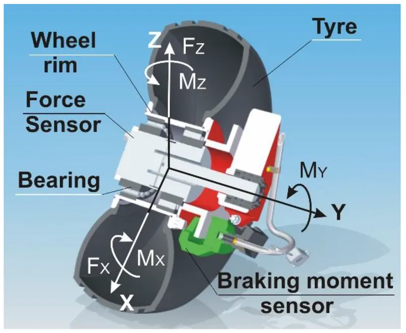
This paper describes airfield measurement of forces and moments that act on a landing gear wheel. For the measurement, a wheel force sensor was used. The sensor was designed and built based on strain gage technology and was embedded in the left landing gear wheel of a test aircraft. The sensor is capable of measuring simultaneously three perpendicular forces and three moments and sends data to a handheld device wirelessly. For the airfield tests, the sensor was installed on a PZL 104 Wilga 35A multipurpose aircraft. The aircraft was towed at a “marching man” speed and the measurements were performed at three driving modes: Free rolling, braking, and turning. The paper contains results obtained in the field measurements performed on a grassy runway of the Rzeszów Jasionka Aerodrome, Poland. Rolling resistance of aircraft tire, braking friction, as well as aligning moment were analyzed and discussed with respect to surface conditions.
Keywords: airfield performance, landing gear, wheel, force and moment measurement, strain gage, wheel force sensor, wireless data transfer, grassy airfield, GARFIELD System
Airfield performance of an airplane plays an important role in the analysis of takeoff and landing and determines, among others, ground roll distances. Forces and moments that act on aircraft landing gear wheels are effects of gravitational acceleration, as well as surface reactions. These reactions are easily obtainable on paved runways, but difficulties arise when an airplane operates on unpaved, grassy, or gravel surfaces. One method is to monitor surface mechanical data, related to weather conditions. The GARFIELD information system [1] is based on a wheel–grass model that includes analysis of wheel–soil (wheel–grassy surface) interactions considering soil modeling with a special caution to loads by aircraft tires [2]. The model will respect non-linear, dynamic effects such as hyper-elastic tire deflection, rheological soil response to high rate deformation, and effects of grass and roots. The wheel–grass model also employs the analysis of weather impact upon mechanical characterization of runway surface, which can be identified and verified by means of wheel–force measurements in full-scale tests [3].
Researchers dealing with flight tests of aircraft, piloted or unmanned, pay significant attention to the importance of ground tests, including measurements for the validation and verification of landing gear systems [4,5,6].
Significant emphasis is placed on the development and research of new measuring technologies and, as an example, a new solution in the field of strain gauge sensors can be cited. Pecora et al. have presented an innovative strain gauge for monitoring of inflatable structures, suitable for an use in aerospace [7]. Another interesting example is given by Petritoli et al. (2019-1), who investigated uncertainty and measured errors of an inertial navigation systems for UAV (Unmanned Aerial Vehicle) [8]. Petritoli et al. (2018) and Petritoli et al. (2019-2) targeted the problem of collocation of the sensors to be installed in a UAV with a reduced space, together with the allocation of the payload [9,10]. This problem is vital for full size aircrafts, not only typically smaller UAVs, especially if a sensor has to be embedded in an existing part of an aircraft. Eling et al. (2015) presented an innovative georeferencing system for the guidance, navigation, and control of UAVs [11]. This is an example of an inertial measurement unit (IMU)-based system, the method of a wide spectrum of applications in aerospace.
Measurement of forces and moments that act on a road wheel is a well known practice in automotive research and development. It is usually done either on laboratory test stands or on a test vehicle. Either way, a device that provides wheel forces and moments is a wheel dynamometer. A wheel dynamometer is a measuring device that enables to measure forces and moments acting on a wheel in real time on a moving vehicle. The majority of wheel dynamometer solutions comes from the automotive industry or research, and a typical solution has a form of a 6-element sensor that measures three orthogonal forces, FX, FY, and FZ, together with corresponding moments, MX, MY, and MZ [12,13,14,15]. The measurement principle is based either on the strain gage or piezoelectric sensor technology. Some selected works that describe the use of such dynamometer systems for measurement of wheel forces and moments in various applications are included in the reference list [16,17,18,19].
The horizontal force, FX, measured by a wheel dynamometer can be correlated with bending or shearing the grass plants, as well as soil deformation. The braking friction force can be correlated with sliding over the grass. The vertical force, Fz, depends the grass compression and can be used for coefficient calculations (braking friction, μ, and rolling resistance, kRR, coefficients, as well as aligning moment, MZ). This approach is alternative to commonly used laboratory drop tests of landing gear [20,21,22]. The aim of this study was to apply a wheel force and moment sensor for measurement of aircraft landing gear on grassy surface. The primary paper, entitled Measurement of Forces and Moments Acting on Aircraft Landing Gear Wheel, was presented during the 2019 IEEE International Workshop Metrology for Aerospace in Torino, Italy [23].
Wheel Dynamometer System
The wheel dynamometer system used in the experiment consisted of a sensor, modified wheel and tire, wireless data transfer unit, and software. The sensor core was made of steel, and strain gages were used as sensing elements. The instrumentation amplifiers, which prepare the outgoing signals for data acquisition, were placed outside the sensor in a small box, together with a board of the microprocessor data analysis and transfer system. Figure 1 shows a schematic of the sensor, but without the electronics. This schematic also includes the orientation of forces and moments.