Project-1: Powertrain for aircraft in runways
Powertrain for Aircraft in Runways : (Project 1{IHEV} )
Objective:
- Search and list out the total weight of various types of aircrafts.
- Is there any difference between ground speed and air speed?
- Why is it not recommended to use aircraft engine power to move it on the ground at Airport?
- How an aircraft is pushed to runway when its ready to take off?
- Learn about take off power, tyre design, rolling resistance, tyre pressure, brake forces when landing.
- A. With necessary assumptions, calculate the force and power required to push / pull an aircraft by a towing vehicle.
- Develop the model for the calculated force and power using Simulink.
- A. Design an electric powertrain with type of motor, it’s power rating, and energy requirement to fulfill aircraft towing application in Simulink. Estimate the duty cycle range to control the aircraft speed from zero to highest. Make all required assumptions. Prepare a table of assumed parameters. Draw a block diagram of powertrain.
- (Hint :DC7 Block)
- Also, Design the parameters in excel sheet.
#Study 1: Search and list out the total weight of various types of aircrafts.
The weight of the aircraft is needed to be calculated by the pilot for every flight to ensure the aircraft remains within weight limitations set by the manufacturer. These limitations are to ensure the aircraft is able to perform and recover from all flight maneuvers and withstand structural loading.
Aircraft Total Weight List:
|
Aircraft |
Empty Weight |
Max Fuel Weight |
Max Cargo Weight |
Max Gross Takeoff Weight |
|
628,000 lbs |
661,400 lbs |
417,000 lbs |
1,411,000 lbs |
|
|
611,000 lbs |
560,000 lbs |
185,000 lbs |
1,268,000 lbs |
|
|
485,300 lbs |
427,400 lbs |
295,000 lbs |
987,000 lbs |
|
|
370,000 lbs |
386,300 lbs |
119,000 lbs |
820,000 lbs |
|
|
370,000 lbs 168,000 kg |
320,800 lbs 145,500 kg |
148,000 lbs |
776,000 lbs |
|
|
299,000 lbs 135,500 kg |
223,500 lbs |
126,300 lbs 57,300 kg |
560,000 lbs |
|
|
98,500 lbs |
53,100 lbs |
44,600 lbs |
187,000 lbs |
|
|
93,900 lbs |
48,700 lbs |
44,000 lbs |
150,000 lbs |
|
|
63,500 lbs |
28,600 lbs |
28,800 lbs |
106,000 lbs |
|
|
54,000 lbs 24,500 kg |
48,200 lbs 21,900 kg |
6,500 lbs |
100,000 lbs |
|
|
48,160 lbs 21,850 kg |
19,600 lbs 8,900 kg |
6,075 lbs 2,760 kg |
80,500 lbs |
|
|
39,300 lbs |
11,700 lbs |
18,700 lbs |
62,000 lbs |
|
|
13,900 lbs 6,300 kg |
6,060 lbs |
2,900 lbs |
21,500 lbs |
|
|
10,300 lbs 4,700 kg |
5,800 lbs |
2,200 lbs 1,000 kg |
17,200 lbs |
|
|
7,100 lbs 3,200 kg |
3,200 lbs |
4,150 lbs |
12,000 lbs |
|
|
3,200 lbs |
340 lbs |
1,250 lbs |
4,400 lbs |
|
|
2,500 lbs 1,150 kg |
450 lbs |
850 lbs |
3,660 lbs |
|
|
2,200 lbs |
520 lbs |
1,150 lbs |
3,600 lbs |
|
|
2,250 lbs 1,000 kg |
485 lbs |
950 lbs |
3,600 lbs |
|
|
1,700 lbs |
380 lbs |
560 lbs |
2,425 lbs |
Aircraft Empty Weight (AEW)
This is sometimes referred to as OEW – Operating Empty Weight and it is the weight of the aircraft with all its equipment on board but no fuel, no passengers or no cargo.Think of this like the aircraft has just come out of the factory and is sitting waiting to be fueled up for delivery to the customer.
Aircraft Maximum Gross Takeoff Weight (MGTW)
This is the maximum permissible weight the aircraft can weigh as it lifts off the ground at takeoff. This includes the aircraft’s empty weight, the fuel, the crew, the passengers, and all the cargo.
This weight limit is set by the manufacturer and is gospel. Many aircraft accidents have been caused by an aircraft being overweight and the pilot/s have not had enough power or maneuverability to prevent the accident.
Aircraft Useful Load
This is the weight that a pilot can place in the aircraft. Take the MGTW figure and subtract the AEW and this is the total useful load that can be placed into the aircraft. This is the fuel, crew, passengers, and cargo. The bigger the load, the more useful the aircraft can be to its customers!
Importance of Aircraft Total Weight:
- Proper distribution of weight plays a large and important role in an aircraft’s overall performance. Load your airplane improperly, and it will affect its fuel consumption, speed, rate of climb, controllability, ceiling, and even structural integrity.
- When building your own airplane, determining its weight and balance before its first flight is critical to your safety—and the safety of those who will fly with you. Take care and all the time necessary to determine accurate weight and balance numbers.
- Like production aircraft, homebuilt must have accurate weight and balance data when they are certificated, and when the FAA examines your completed project, the inspector will want to see your weight and balance paperwork.
References:- https://pilotteacher.com/how-much-do-airplanes-weigh-with-20-examples/
#Study 2: Is there any difference between ground speed and air speed.
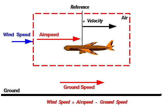
One of the most confusing concepts for young scientists is the relative velocity between objects. Aerodynamic forces are generated by an object moving through a fluid (liquid or gas). A fixed object in a static fluid does not generate aerodynamic forces. Hot air balloons "lift" because of buoyancy forces and some aircraft like the Harrier use thrust to "lift" the vehicle, but these are not examples of aerodynamic lift. To generate lift, an object must move through the air, or air must move past the object. Aerodynamic lift depends on the square of the velocity between the object and the air. Now things get confusing because not only can the object be moved through the air, but the air itself can move. To properly define the relative velocity, it is necessary to pick a fixed reference point and measure velocities relative to the fixed point. In this slide, the reference point is fixed to the ground, but it could just as easily be fixed to the aircraft itself. It is important to understand the relationships of wind speed to ground speed and airspeed.
Wind Speed
For a reference point picked on the ground, the air moves relative to the reference point at the wind speed. Notice that the wind speed is a vector quantity and has both a magnitude and a direction. Direction is important. A 20 mph wind from the west is different from a 20 mph wind from the east. The wind has components in all three primary directions (north-south, east-west, and up-down). In this figure, we are considering only velocities along the aircraft's flight path. A positive velocity is defined to be in the direction of the aircraft's motion. We are neglecting cross winds, which occur perpendicular to the flight path but parallel to the ground, and updrafts and downdrafts, which occur perpendicular to the ground.
Ground Speed
For a reference point picked on the ground, the aircraft moves relative to the reference point at the ground speed. Ground speed is also a vector quantity so a comparison of the ground speed to the wind speed must be done according to rules for vector comparisons.
Airspeed
The important quantity in the generation of lift is the relative velocity between the object and the air, which is called the airspeed. Airspeed cannot be directly measured from a ground position, but must be computed from the ground speed and the wind speed. Airspeed is the vector difference between the ground speed and the wind speed.
Airspeed = Ground Speed - Wind Speed
On a perfectly still day, the airspeed is equal to the ground speed. But if the wind is blowing in the same direction that the aircraft is moving, the airspeed will be less than the ground speed.
Examples
Suppose we had an airplane that could take off on a windless day at 100 mph (liftoff airspeed is 100 mph). We are at an airport with an east-west runway that is 1 mile long. The wind is blowing 20 mph towards the west and the airplane takes off going east. The wind is blowing towards the aircraft which we call a headwind. Since we have defined a positive velocity to be in the direction of the aircraft's motion, a headwind is a negative velocity. While the plane is sitting still on the runway, it has a ground speed of 0 and an airspeed of 20 mph:
Airspeed = Ground Speed (0) - Wind Speed (-20) = 20 mph
The airplane starts its take off roll and has a constant acceleration a. From Newton's second law of motion, the ground speed V at any time t is:
V = a * t
and the distance d down the runway at any time is:
d = 1/2 * a * t^2
For a fixed length runway, this specifies the time to be used in the velocity equation. Let's assume that at 5000 feet down the runway, the velocity is 80 mph. Then the airspeed is given by
Airspeed = Ground Speed (80) - Wind Speed (-20) = 100 mph
and the airplane begins to fly. Now another pilot, with exactly the same airplane decides to take off to the west. The wind is now in the same direction as the motion and this is called a tailwind. The sign on the wind speed is now positive, not negative as with the headwind. The acceleration along the ground is the same, so at 5000 feet down the runway, the ground speed is again 80 mph. The airspeed is then given by:
Airspeed = Ground Speed (80) - Wind Speed (20) = 60 mph
This airplane doesn't have enough airspeed to fly. It runs off the end of the runway!
Ground Speed vs Air Speed:-
- As mentioned above, true airspeed is simply the speed at which an aircraft is moving relative to the air it is flying in. As such, it’s also the speed at which the air is flowing around the aircraft’s wings.
- Ground speed, on the other hand, is the aircraft’s speed relative to the ground. One thing that should be noted here is that it’s its horizontal rather than vertical speed – an aircraft climbing completely vertically would have a ground speed of zero.
- In other words, while airspeed is what determines whether there is enough airflow around an aircraft to make it fly, ground speed is what determines how fast an aircraft will get to its destination.
- The relationship between airspeed and ground speed is fairly simple. Ground speed is simply the sum of airspeed and wind speed.
- If the aircraft is flying in the same direction as the wind is blowing, the aircraft experiences tailwind, and its ground speed is higher than its airspeed. On the other hand, if the wind is blowing against the direction the aircraft is traveling in, the aircraft experiences headwind, and its ground speed is lower than its airspeed.
References:- https://www.grc.nasa.gov/www/k-12/airplane/move.html
#Study 3: Why is it not recommended to use aircraft engine power to move it on the ground at Airport?
- The term Aircraft Ground Running is usually used to describe the operation of some or all of the engines of an aircraft, whilst on the ground, for the purpose of functionally checking the operation of either engines or aircraft systems. This usually takes place prior to the Release to Serviceof an aircraft from maintenance. Ground running may be carried out either prior to, during or after the rectification of a defect or scheduled work on an engine or an aircraft system, when this requires engines to be operating in order to assess its function.
- The risks which may arise from engine ground running relate to the potential for loss of controlof the aircraft by those persons occupying the pilot seats in the flight deck. In most cases, such persons will be maintenance personnel holding specific company-issued approval for the required tasks. The consequences of loss of control during taxi or towing are the same as apply to these operations generally and this article is concerned only with the risks arising from the static running of one or more aircraft engines. Unwanted consequences from such static running are mainly related to those arising from the unintended movement of the aircraft during engine running - effectively a loss of control especially during high power engine running. Damage can occur to the aircraft itself, other aircraft nearby or to airside structures. In addition, there is a risk of injury to ground support personnel who may be in relatively close proximity to the aircraft.
- The best form of overall mitigation is to ensure that all persons authorised to supervise or directly participate in engine ground running from the flight deck, who are not pilots or flight engineers currently rated on the specific aircraft type, are in receipt of suitable initial training and that there is a proper system for both initial and recurrent qualification for engine ground running duties. Both initial and recurrent qualification must include practical training and assessment of task competence using either a full flight simulator or an aircraft. Between formal competency assessments, a maximum interval between performance of the qualified task should be specified. If that interval is exceeded, the qualification would become void until remedial action has been competed. In this respect, the task of engine ground running should be seen as part of a broader group of aircraft ground movement tasks which can be carried out under the control of flight deck occupants other than type rated flight crew.
#Study 4: How an aircraft is pushed to runway when its ready to take off
- The apron handler removes the chocks. A so-called pushback truck reverses the aircraft into taxiing position, pushing it with a towbar attached to the nose-wheel strut. Or, in the most modern versions, by actually lifting the wheel. That speeds up coupling and decoupling.
- The aircraft taxis to the runway to depart at the agreed time.
- Due to safety reason it is true that most of the time, a small vehicle is needed to push the larger commercial airplanes backwards away from the terminal building, because even if a plane can reverse it’s thrust, it’s not always safe to hit the buildings with that reverse thrust. So the little trucks push the bigger planes back away from the buildings, but after that, the planes can apply a small amount of engine power to roll forward just as all airplanes can.
- Large jetliner passenger aircraft are pushed away from the passenger loading gate by a tug. This is a machine with wheels, some form of power such as an internal combustion engine, or a battery. When the large aircraft is being pushed backwards, there is someone on each wing tip. They are looking out to make sure nothing will touch the aircraft. The whole idea is to avoid expensive crunching noises.
- An airliner might be pushed backwards off the ramp, and onto a taxi way. Then the engines can start, the aircraft can proceed forward under its own power. A twin engine jet might not start the second engine until it is close to takeoff runway, clearance is certain.
- A piston engine can run at idle power using only a small percentage of the fuel consumption used at operating power level. Turbine engines such as modern airliner turbo fan engine burn a lot of fuel once they are started. So, there is a lot of incentive to not run them until it is time to fly.
- The GE90's 10-stage high-pressure compressor developed a then-industry record pressure ratio of 23:1 and is driven by a 2-stage, air-cooled, HP turbine. A 3-stage low-pressure compressor, situated directly behind the fan, supercharges the core. The fan/LPC is driven by a 6-stage low-pressure turbine.
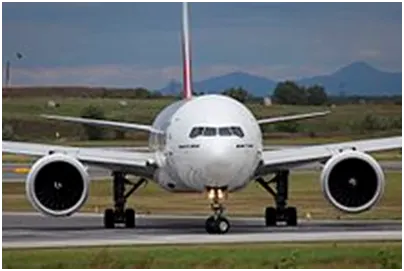
- The GE90-115B is powerful enough to fly GE's Boeing 747-100testbed with the other engines at idle, an attribute demonstrated during a flight test. According to the Guinness Book of Records, at 127,900 lbf (569 kN), the engine holds the record for the highest thrust (although rated at 115,300 lbf (513 kN)).
- This type of high thrust engine not safe, because even if a plane can reverse it’s thrust, it’s not always safe to hit the buildings with that reverse thrust.
#Study 5: Learn about take off power, tyre design, rolling resistance, tyre pressure, brake forces when landing.
Take off Power:
Take off is two types- 1. Horizontal Take off
2.Vertical Take off.
Horizontal Take off:
- Horizontal Take-Off was a British design for an Airbreathing jet engine spaceplane by Rolls-Royce and British Aerospace.
- Designed as a single-stage-to-orbit (SSTO) reusable winged launch vehicle, it was to be fitted with a unique air-breathing engine, the RB545 or Swallow, to be developed by the Rolls-Royce company. The engine was technically a liquid hydrogen/liquid oxygen design, but dramatically reduced the amount of oxidizer needed to be carried on board by utilising atmospheric oxygen as the spacecraft climbed through the lower atmosphere.
- Since propellant typically represents the majority of the takeoff weight of a rocket, HOTOL was to be considerably smaller than normal pure-rocket designs, roughly the size of a medium-haul airliner such as the McDonnell Douglas DC-9/MD-80. Ultimately, comparison with a rocket vehicle using similar construction techniques failed to show much advantage, and funding for the vehicle ceased.
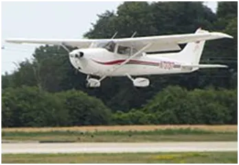
- CTOLis an acronym for conventional take-off and landing,and is the process whereby conventional aircraft (such as passenger aircraft) take off and land, involving the use of runways.
- STOL is an acronym forshort take-off and landing, aircraft with very short runway requirements.
- RTOL is an acronym forReduced take-off and landing.
- CATOBAR(Catapult Assisted Take-Off But Arrested Recovery or Catapult Assisted Take-Off Barrier Arrested Recovery) is a system used for the launch and recovery of aircraft from the deck of an aircraft carrier. Under this technique, aircraft launch using a catapult-assisted take-off and land on the ship (the recovery phase) using arrestor wires.
- STOBAR(Short Take-Off But Arrested Recovery) is a system used for the launch and recovery of aircraft from the deck of an aircraft carrier, combining elements of both short take-off and vertical landing (STOVL) with catapult-assisted take-off but with arrested recovery (CATOBAR).
Vertical Take off:
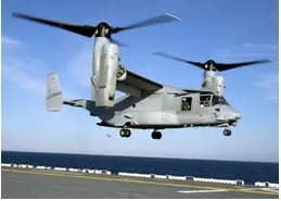
- VTOL is an acronym for vertical take-off and landing aircraft. This classification includes fixed-wing aircraft that can hover, take off and land vertically as well as helicopters and other aircraft with powered rotors, such as Theterminology for spacecraft and rockets is VTVL(vertical takeoff with vertical landing).Some VTOL aircraft can operate in other modes as well, such as CTOL (conventional take-off and landing),STOL (short take-off and landing), and/or STOVL (short take-off and vertical landing). Others, such as some helicopters, can only operate by VTOL, due to the aircraft lacking landing gear that can handle horizontal motion. VTOL is a subset of V/STOL (vertical and/or short take-off and landing).
- A short take-off and vertical landing aircraft (STOVL aircraft) is a fixed-wing aircraft that is able to take off from a short runway (or take off vertically if it does not have a heavy payload) and land vertically (i.e. with no runway).
- VTOHL Vertical Take-Off and Horizontal Landingas well as several VTOHL aviation-specific subtypes: VTOCL,VTOSL, VTOBAR exist.
Take off Power:
- For light aircraft, usually full power is used during takeoff. Large transport category(airliner) aircraft may use a reduced power for takeoff, where less than full power is applied in order to prolong engine life, reduce maintenance costs and reduce noise emissions. In some emergency cases, the power used can then be increased to increase the aircraft's performance.
- The total energy of an aircraft flying in the atmosphere can be calculated using equation 1.
E = ½ m v2 + mgh
- A Boeing 737-300 has a maximum takeoff weight of 5.65 × 10⁴kg, a cruise altitude of h = 10,195 m, and cruise speed of 221 m/sec. Inserting these numbers into the above equation, we obtain 7.03 GJ for the energy at cruise conditions. However, the engines mounted onto the wings of the plane are required to provide additional energy per time, power, in order to keep the aircraft flying at a constant altitude and speed. This extra power needed to overcome the drag acting on the airplane and is calculated using
P = (dh/dt) m g
- where (dh/dt) is the decent speed required to keep the plane's speed constant if the engines fail. Assuming that a Boeing 737-300 has a similar glide ratio to a Boeing 747 of 17:1, a Boeing 737-300 has a descent speed of approximately (dh/dt)= (221m/sec)/17 = 13 m/sec. The power required to keep a Boeing 737-300 flying at a constant altitude and speed is 7.2 × 10⁶ The rate of fuel burn necessary for the engines to produce enough power to keep the airplane flying can be calculated from the total power requirement. Assuming the efficiency of the engines adding thrust to the aircraft is roughly 30% and the specific gravity of jet fuel is about 0.82 kg per liter, a Boeing 737-300 burns approximately 0.665 liters per second. A Boeing 737-300 has a standard fuel capacity of 2.0104 × 10⁴liters. Assuming that takeoff, climb, and landing burns approximately one third of the total fuel, and at cruise conditions with a fuel burn rate of 0.665 liters per second, a Boeing 737-300 can fly for approximately (2/3) × 8.4 hours= 5.6 hours at cruise conditions before running out of jet fuel.
- If all the engines were to completely fail, jet aircrafts would not have any of the required power to keep flying at a constant altitude, and thus descend to the ground. As the aircraft is gliding towards the ground the glide angle, glide slope, and glide ratio can be calculated based on the aircraft specifications. The glide angle (γ) is the angle of the aircraft's nose relative to the horizon. In cruise conditions, the smallest glide angle occurs when the drag per unit weight is minimized and/or the lift-to-drag ratio is maximized. The glide ratio of an airplane, with no power, is the ratio of the forward travel to the loss of altitude. The glide ratio of a Boeing 747 is 17:1 meaning that for every 1,000ft of altitude lost, the Boeing 747 will travel 17,000ft.
- The glide angle (γ) is related to the glide slope by tan(γ) and the glide ratio is calculated as the inverse of the glide slope, cot(γ). Using glide ratio of 17, the glide angle (γ) is calculated using the relationship, glide ratio= cot(γ). The glide angle for the Boeing 747 is approximately 3.4 degrees.
References: http://large.stanford.edu/courses/2013/ph240/eller1/
Tire Design:
- Designing aircraft tires is a very intense undertaking. Once an aircraft manufacturer goes to the tire manufacturer with the size and weight requirements, the tire manufacturer begins the process of designing a tire that meets the needs of the aircraft manufacturer as well as all regulatory requirements — including foreign regulations in many cases.
Engineers are challenged with designing tires with cool running, heat-resistant materials while simultaneously exceeding tire service requirements. Tire prototypes are put through rigorous tests that simulate cycles of landings, take-offs, and taxi operations. It is only after the tires pass all mandatory tests and meet the
- Aircraft tires may be tube-type or tubeless. They support the weight of the aircraft while it is on the ground and provide the necessary traction for braking and stopping. The tires also help absorb the shock of landing and cushion the roughness of takeoff, rollout, and taxi operations. Aircraft tires must be carefully maintained to perform as required. They accept a variety of static and dynamic stresses and must do so dependably in a wide range of operating conditions.
Classification:
Aircraft tires are classified in various ways including by: type, ply rating, whether they are tube-type or tubeless, and whether they are bias ply tires or radials. Identifying a tire by its dimensions is also used. Each of these classifications is discussed as follows.
Type:
A common classification of aircraft tires is by type as classified by the United States Tire and Rim Association. While there are nine types of tires
Types I, III, VII, and VIII.
Type I tires are manufactured, but their design is no longer active. They are used on fixed gear aircraft and are designated only by their nominal overall diameter in inches. These are smooth profile tires that are obsolete for use in the modern aviation fleet. They may be found on older aircraft.
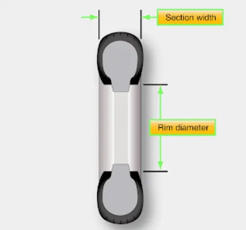
Type III tires are common general aviation tires. They are typically used on light aircraft with landing speeds of 160 miles per hour (mph) or less. Type III tires are relatively low-pressure tires that have small rim diameters when compared to the overall width of the tire. They are designed to cushion and provide flotation from a relatively large footprint. Type III tires are designated with a two number system. The first number is the nominal section width of the tire, and the second number is the diameter of the rim the tire is designed to mount upon. [Figure 1]
Bias-ply tire construction
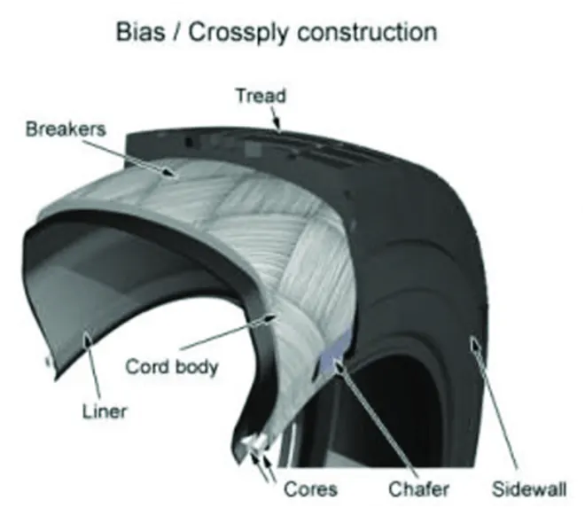
Figure - 1
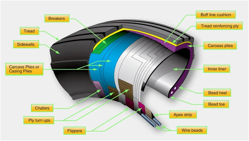
A cutaway of a typical bias-ply tire is shown in Figure 1. Bias-ply tires are popular choices for aircraft tires because of their durability and retreadability. The tire construction consists of the following components:
Tread: The tread is made of rubber mixed with other additives to obtain the desired level of toughness, durability, and resistance to wear. The tread pattern is designed to aircraft operational requirements, with the ribbed tread design used widely due to its good traction under varying runway conditions.
Sidewall: The sidewall is a protective layer of rubber that covers the outer casing ply. It extends from the tread edge to the bead area.
Tread Reinforcing Ply: One or more layers of fabric that strengthens and stabilizes the tread area for high-speed operation. It also serves as a reference for the buffing process when tires are retreaded.
Buff Line Cushion: The buff line cushion is made of rubber compound to enhance the adhesion between the tread reinforcing ply and the breakers or casing plies. It is of sufficient thickness to allow for the removal of the old tread when the tire is retreaded.
Breakers: Breakers are reinforcing plies of rubber-coated fabric placed under the buff line cushion to protect casing plies and strengthen and stabilize the tread area. They are considered an integral part of the casing construction.
Casing Plies: Alternate layers of rubber-coated fabric (running at opposite angles to one another) provide the strength of the tire.
Wire Beads: Hoops of high tensile strength steel wire that anchor the casing plies and provide a firm mounting surface on the wheel. The outer edge of the bead that fits against the wheel flange is called the bead heel. The inner bead edge is called the bead toe.
Apex Strip: A wedge of rubber affixed to the top of the bead bundle.
Flippers: Layers of rubberized fabric that help anchor the bead wires to the casing and improve the durability of the tire.
Ply Turnups: The casing plies are anchored by wrapping them around the wire beads, thus forming the ply turnups.
Chafer: A protective layer of rubber and/or fabric located between the casing plies and wheel to minimize chafing.
Liner: In tubeless tires, the liner is a layer of low permeability rubber that acts as a built-in tube and restricts gas from diffusing into the casing plies. In tube-type tires, a thinner liner is used to prevent tube chafing against the inside ply.
Radial-ply tire construction
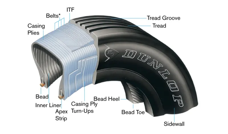
Figure - 2
A typical radial tire is illustrated in Figure 2. With their rigid belt, they provide increased landings and reduced rolling resistance. They have fewer components in their construction and are lighter than similarly sized bias ply tires. Components that differ from bias-ply construction as follows:
Overlay: A layer of reinforcing rubber coated fabric placed on top of the belts to aid in high speed operation.
Belt Plies: A composite structure that stiffens the tread area for increased landings. The belt plies increase the tire strength in the tread area.
Casing Plies: As in bias-ply tires, the casing plies are layers of rubber-coated fabric. However, unlike those in bias plies that run at opposite angles to one another, radial plies run radially from bead to bead.
Chippers: The chippers are layers of rubber-coated fabric applied at diagonal angles that improve the durability of the tire in the bead area.
Rolling Resistance:
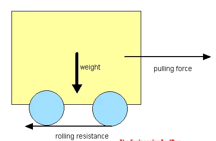
Rolling resistance is the combination of forces that work against the forward motion of your vehicle. The weight of the vehicle, gravity and inertia, the amount of friction between the tires and the road surface, and air drag all play a part. When you coast in your car or on a bike, rolling resistance is what slows you down. The more rolling resistance, the more power it takes to propel a vehicle.
`F= C_rr N`
F = force
`C_rr`= Dimensionless rolling resistance coefficient
N = normal force.
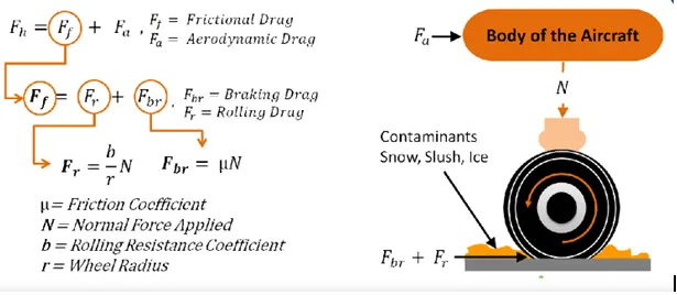
- Rolling resistance coefficient (RRC). The value of the rolling resistance force divided by the wheel load. The Society of Automotive Engineers (SAE) has developed test practices to measure the RRC of tires. These tests (SAE J1269and SAE J2452) are usually performed on new tires. When measured by using these standard test practices, most new passenger tires have reported RRCs ranging from 0.007 to 0.014."[6] In the case of bicycle tires, values of 0.0025 to 0.005 are achieved. These coefficients are measured on rollers, with power meters on road surfaces, or with coast-down tests. In the latter two cases, the effect of air resistance must be subtracted or the tests performed at very low speeds.
- The coefficient of rolling resistance b, which has the dimension of length, is approximately (due to the small-angle approximationof equal to the value of the rolling resistance force times the radius of the wheel divided by the wheel load.
- ISO 18164:2005is used to test rolling resistance in Europe.
Tire Pressure:
- Different aircraft have different tire pressure but normally aircraft tire pressure 200 psi above.
- Depends on the weight of the plane and number of tires it has, but generally the cold pressure is between 200 and 300+ psi.
- They are rubber, like a car tire but specially formulated to stay flexible at -60 Deg F at altitude. They are still very cold after descent to touchdown.
- They are almost all radial tires but without steel belts. Kevlar is used as they do not have to withstand the road hazards a car tire does.
- Passenger airliners have tires inflated to 200 or more psi. Another answer says the Boeing 777 has 14 tires. Larger airliners have 22 or even 32 tires. The tires are made out of basically the same stuff as your car tires but engineered for a specific application.
Brake force when landing:
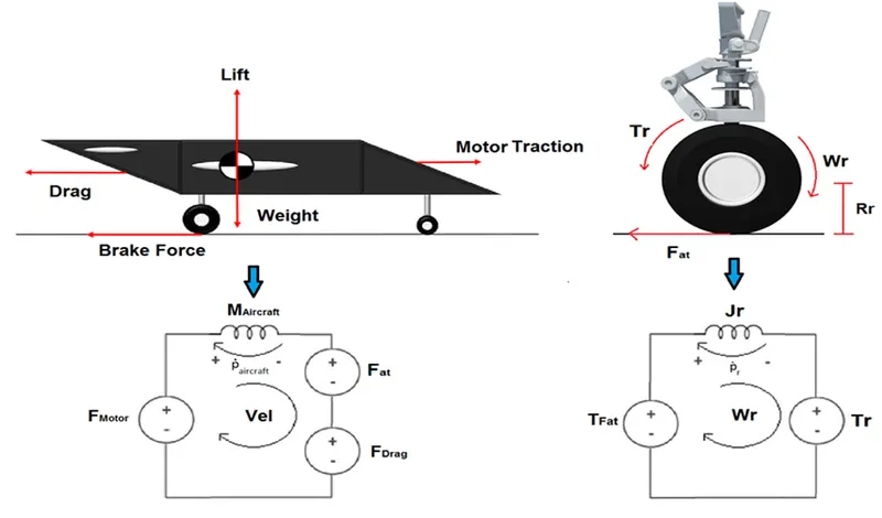
- Brakes provide this critical stopping function during landings to enable airplanes to stop within the length of the runway. They also stop aircraft during rejected takeoff events, in which an attempted takeoff is canceled as the airplane is rolling down the runway before it lifts off from the ground due to engine failure, tire blowout, other system failure or direction from air traffic control.
- Aircraft brakes also prevent motion of the aircraft when it is parked, limit its speed during taxiing and can even help steer the aircraft on the ground by applying different levels of braking force to the left- and right-side brakes.
- Stopping a 200-tonne aircraft landing at 180 mph requires a lot of braking force. To do this, the 787 has one brake unit on each of the eight wheels on the main gear assembly. On other aircraft types, the brake units are powered by the hydraulics system. An electrical signal is sent from the flight deck to hydraulic actuators near the main landing gear. Here, hydraulic fluid at 3,000 pound per square inch is used to force the brake unit against the wheel, thus slowing it down.
- This system works fine, but the pipes and actuators that form this part of the hydraulic system come at a considerable weight cost. Extra weight means more fuel burn, which in turn increases costs and carbon emissions. What if the brakes could be powered a different way?
#Study 6: A. With necessary assumptions, calculate the force and power required to push / pull an aircraft by a towing vehicle.
- Develop the model for the calculated force and power using Simulink.
A. With necessary assumptions, calculate the force and power required to push / pull an aircraft by a towing vehicle.
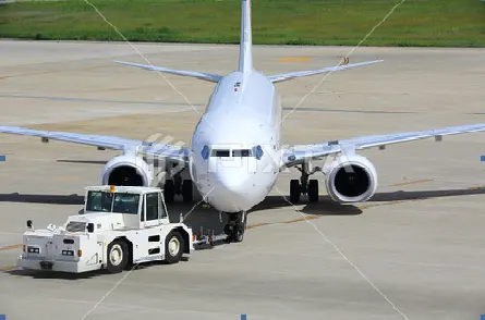
The force to move an airplane on an absolute flat runway with no wind at constant low speed is equal to the rolling resistance between the plane and the tarmac.
The rolling resistance for the air plane can be calculated as
Fr = c mr ag (1)
where
Fr = rolling resistance (N, lbf)
c = rolling resistance coefficient
mr = rolling mass (kg, lbm)
ag = acceleration of gravity (9.81 m/s2)
If the mass of a plane is 40000 kg and the rolling coefficient between the aircraft wheel and the tarmac is 0.02 - the force required to overcome the rolling resistance can be calculated as
Fr = 0.02 (40000 kg) (9.81 m/s2)
= 7848 N
This force can be delivered by a pulling truck or - as occasionally seen - by a number of pulling people. Enough weight for the pullers are required to create friction forces against the tarmac that equals the plane rolling resistance.
The friction force for the puller can be calculated to
Ff = μ W
= μ mf ag (2)
where
Ff = frictional force (N, lb)
μ = friction coefficient
W = weight (N, lbf)
mf = friction mass (kg)
Example - Required Mass for Pulling Truck
The friction coefficient between a pulling truck rubber wheels and dry tarmac is 0.9. Since pulling trucks are connected to air crafts nose wheels close to tarmac we simplify the calculation of required truck mass to
mf = (7848 N) / (0.9 (9.81 m/s2))
= 889 kg
- Develop the model for the calculated force and power using Simulink.
Simulink Model:
Model Description:
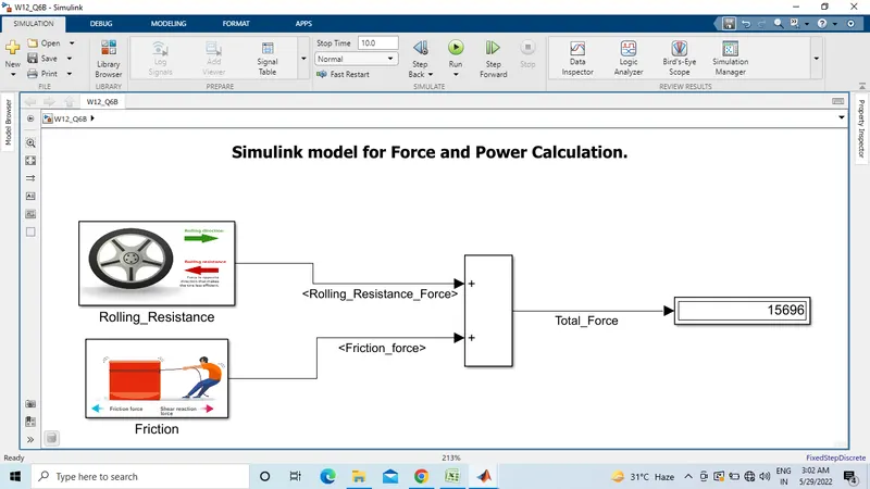
- When towing vehicle tow the aircraft then two forces are occurs rolling resistance force and friction force of wheel.
- I made two subsystem block for two forces and calculate the power.
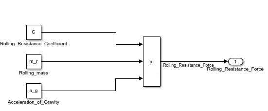
- First subsystem block I put rolling resistance coefficient (c) , Rolling mass(m_r) and Acceleration of gravity (a_g) . then connect with product block and product block connected with output block. Figure shown below.
- Second subsystem block is friction force block. This block I put rolling resistance block of wheel , friction coefficient( ) and acceleration of gravity(a_g) . then these three block connected with product and divide block according else-if condition. then connected with output block . figure shown below.
- Both the subsystem connected with add block and add block connected with display block.
- Result shown in figure.
#Study 7: A. Design an electric powertrain with type of motor, it’s power rating, and energy requirement to fulfill aircraft towing application in Simulink. Estimate the duty cycle range to control the aircraft speed from zero to highest. Make all required assumptions. Prepare a table of assumed parameters. Draw a block diagram of powertrain.
(Hint :DC7 Block)
B.Also, Design the parameters in excel sheet.
A.Design an electric powertrain with type of motor
Calculation:
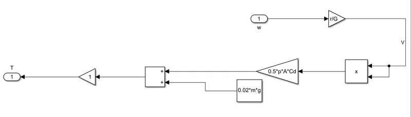
The speed of motor is available at the output of the DC7 Drive block, the speed is then converted into velocity of vehicle by following equation,
V = `r/G ω`
Where
r = radius
G=Nominal Gear ratio
Here we can see that the model is made with the dc drive(DC7) and all necessary blocks with a battery which voltage and current will give the power taken by the model.Here we take initial velocity zero to final velocity V = 15 KM/H(4.167 m/s) that gives equivalent motor speed.
`ω= G/r V`
`ω = 15/0.6*4.167`
`ω=104.175`
And the speed in rpm
N = `(104.175*60)/2π`
N = 995 rpm.
Block Diagram of powertrain:
Simulink Model:
Model Description:
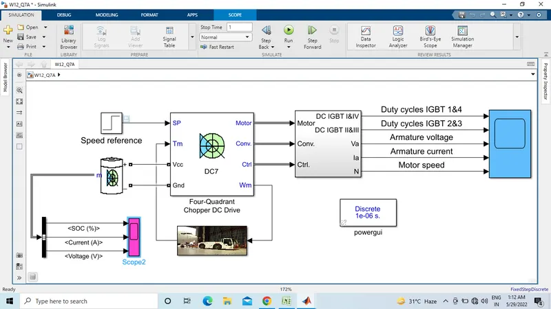
- We used DC7 block. The Four-Quadrant Chopper DC Drive (DC7)block represents a four-quadrant, DC-supplied, chopper (or DC-DC PWM converter) drive for DC motors. This drive features closed-loop speed control with four-quadrant operation. The speed control loop outputs the reference armature current of the machine. Using a PI current controller, the chopper duty cycle corresponding to the commanded armature current is derived. This duty cycle is then compared with a sawtooth carrier signal to obtain the required PWM signals for the chopper.
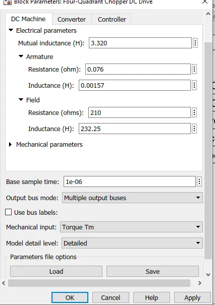
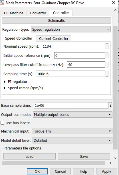
- The main advantage of this drive, compared with other DC drives, is that it can operate in all four quadrants (forward motoring, reverse regeneration, reverse motoring, and forward regeneration). In addition, due to the use of high switching frequency DC-DC converters, a lower armature current ripple (compared with thyristor-based DC drives) is obtained. However, four switching devices are required, which increases the complexity of the drive system.
- A s a speed reference we used step block.
- The Batteryblock implements a generic dynamic model that represents most popular types of rechargeable batteries.
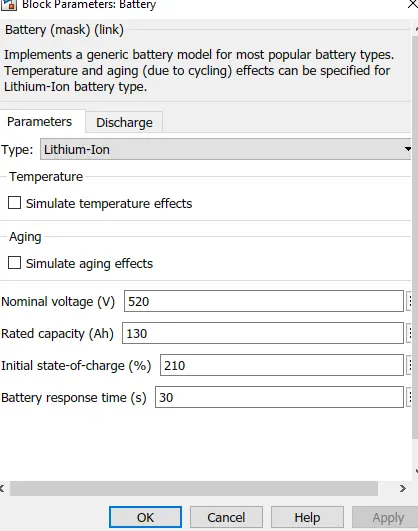
- The powerguiblock allows you to choose one of these methods to solve your circuit.Continuous, which uses a variable-step solver from Simulink.Discretization of the electrical system for a solution at fixed time steps.Continuous or discrete phasor solution.The powergui block also opens tools for steady-state and simulation results.analysis and for advanced parameter design.
- You need the powerguiblock to simulate any Simulink model containing Simscape™ Electrical™ Specialized Power Systems blocks. It stores the equivalent Simulink circuit that represents the state-space equations of the model.
- we made torque speed characteristics subsystem block for DC7 Four quadrant chopper block.
Output Result:
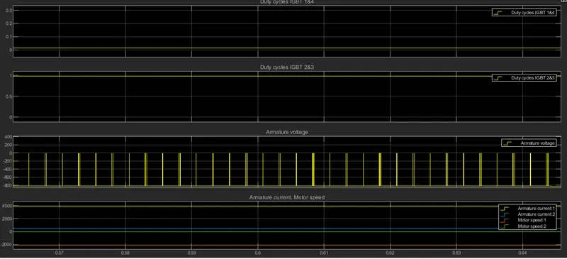
- First slot for duty cycle of IGBT 1& 2 . second slot for duty cycle of IGBT 2&3. Third and fourth graph for armature current and armature voltage. Armature current and motor speed graph both are similar. Motor speed depends on armature current.
- First graph is battery state of charge graph. Second graph is battery input current and third graph is battery voltage.
- Design the parameters in excel sheet.
Parameters excel sheet link- https://docs.google.com/spreadsheets/d/1xvwZs9ikk6ACmzlTJFrEDIjmg5fmfxyg/edit?usp=sharing&ouid=112786727310165782214&rtpof=true&sd=true