Project-1: Powertrain for aircraft in runways
AIM:
To calculate the push/pull force and power required for the vehicle that tows Aircrafts in runways and design an appropriate powertrain.
The following points have to be addressed:
- Search and list out the total weight of various types of aircrafts.
- Is there any difference between ground speed and air speed?
- Why is it not recommended to use aircraft engine power to move it on the ground at Airport?
- How an aircraft is pushed to runway when its ready to take off?
- Learn about take-off power, tire design, rolling resistance, tire pressure, brake forces when landing.
- With necessary assumptions, calculate the force and power required to push / pull an aircraft by a towingvehicle.
- Design an electric powertrain with type of motor, it’s power rating, and energy requirement to fulfill aircraft towing application.Estimate the duty cycle range to control the aircraft speed from zero to highest. Make all required assumptions. Prepare a table of assumed parameters. Draw a block diagram of powertrain.
SOLUTION:
Question.No.1: Search and list out the total weight of various types of aircrafts.
The primary factors that categorize the different types of aircraft are ‘Heavier-Than-Air’ (Aerodyne) and ‘Lighter-Than-Air’ (Aerostat) aircraft.
The next level of classifying is powered and unpowered aircraft. From this point, aircraft designs, technology, and capabilities differ in many different aspects and categories.
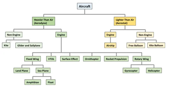
Weights of different aircrafts

These are the typical values of weights (in tons) for different types of aircrafts
Type of Aircraft Weight (tons)
Commercial Aircrafts: 500-600
Business Jets: 7-15
Single Engine Piston: 5-10
Tricycle Gear: 5-10
Taildraggers: 5-10
Helicoptors: 5-22
Seaplanes: 5-10
Airship/Zeplins: 5-10
Heaviest aircrafts are listed below,
- The Antonov An-225 Mriya is a cargo aircraft that was designed by the Antonov design beraue in Ukraine.It is the heaviest aircraft ever build with a maximum takeoff load of 640 tonne.
- The Airbus A380 is a wide-body Aircraft manufactured by Airbus. It is the world's largest passenger air liner
with a maximum takeoff load of 575 tonne - The Boeing 747-8 is a Wide-Body Airliner developed by Boeing commercial Aircrafts, which is the latest
and largest variant of the 747, with a maximum takeoff load of 448 tonne.
lighter aircraft which is used for domestic purposes and some of them are listed below,
- The Boeing 717 is a domestic passenger aircraft that was designed to accomodate 130 passengers. It's
maximum takeoff load is 55 tonne. - The Airbus A319 is a passenger Aircraft manufactured by Airbus. It can accomodate upto 150 passengers and
it's maximum takeoff load is 64 tonne. - The Embraer phenom 300 is a private jet developed by Embraer a brazillian manufacturer, which can take 11
passengers, with a maximum takeoff load of 8 tonne.
________________________________________________________________________________________________________________________
Question.No.2:Is there any difference between ground speed and air speed?
Ground speed is the airplane’s speed relative to the surface of the Earth. It is horizontal rather than vertical speed. Which means that, an aircraft climbing completely vertically would have a ground speed of zero.
Airspeed is its speed relative to the air it is flying in. It can also be called as the speed at which the air is flowing around the aircraft’s wings.
If we compare a ground vehicle such as a car moving in one direction with a speed of x kmph and an aircraft flying at x kmph without any wind, then both will have the same Ground speed. Whereas, if the aircraft experiences wind in the direction of its flight, i.e. it experiences tailwind, then its speed will be x kmph + the wind speed. In this case, the aircraft will be moving faster than the car on ground. Thus, having greater ground speed.
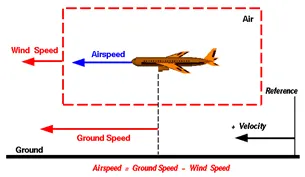
On the other hand, if the wind is blowing against the direction the aircraft is traveling in, the aircraft experiences headwind, and its ground speed is lower than its airspeed.
Thus, we can say that the ground speed is the vector addition of the wind speed and the airspeed.
For tailwind, Airspeed = Ground Speed - Wind Speed
For headwind, Airspeed = Ground Speed + Wind Speed
Other than that, when crosswinds blow, the airspeed & ground speed have to be calculated accordingly by vector additions.
_____________________________________________________________________________________________________________________________________
Question.No.3:Why is it not recommended to use aircraft engine power to move it on the ground at Airport?
Controlling an aircraft in the air is important, but being able to steer it accurately on the ground is equally so.
Taxiing: It refers to an aircraft’s movement while on the ground, under its own power. This term excludes the accelerating run along a runway before takeoff and the decelerating run immediately upon landing.
- By using jet engines as an aircraft’s primary thrust for taxiing, airlines spend huge amounts of jet fuel while still on the ground, which could be much better used for flying. Many airlines plan to adopt electric taxiing (within the aircraft) to save fuel and reduce environmental impacts.
- Even when reversing the aircraft, jet reversers blows debris creating foreign object damage hazard for adjacent aircraft, gate equipment or terminal waiting area glass windows and can also damage the crowded gate area.
- This is accompanied with the high noise that the engine produces.
- The engine produces large thrust from the exit and vacuum from the front which may suck in objects which may damage the engine. Thus, it is not recommended to use the aircraft engine power to move the aircraft on the ground.
Question.No.4:How an aircraft is pushed to runway when its ready to take off?
When aircraft is ready with all the passengers and lugages the aviation, pushback is an Airport procedure during which an Aircraft is
pushed backwards away from an airport gate by external power.
Aircraft Towing Tractors or Tugs
- Pushbacks are carried out by special, low-profile vehicles called pushback tractors or tugs.
- These are heavy weighing low profile vehicles with enourmous torque to do the job of pushing/pulling the large aircraft from the terminals to the runway.
- The Tractors are designed with extra weight purposely to offer them enough Traction to push/pull heavy aircraft.
- Some of the categories of airraft tugs is shown below as per, IATA Airport Handling Ground Support Equipment Specification. There shall be four categories of tractors defined in accordance with the maximum aircraft weight,
Category 1 – aircraft less than 50,000 kg. (110,000 lb.)
Category 2 – aircraft less than 150,000 kg. (330,690 lb.)
Category 3 – aircraft less than 260,000 kg. (573,196 lb.)
Category 4 – aircraft more than 260,000 kg. (573,195 lb.)
The minimum tractor weight for each class,
Category 1 – 4,000 kg. (8,800 lb.)
Category 2 – 12,000 kg. (26,455 lb.)
Category 3 – 18,000 kg. (39,683 lb.)
Category 4 – 40,000 kg. (88,184 lb.)
____________________________________________________________________________________________________________________________________
Question.No.5: Learn about take off power, tyre design, rolling resistance, tyre pressure, brake forces when landing.
(i) Take off power
- Takeoff is the phase of flight in which an aerospace vehicle leaves the ground and becomes airborne.
- For aircraft that take off horizontally, this usually involves starting with a transition from moving along the ground on a runway
- The takeoff speed required varies with air density, aircraft gross weight, and aircraft configuration
- The power from the engine of the aircraft used to achieve the flight is called take off power
- For light aircraft, usually full power is used during takeoff.
- Large transport category (airliner) aircraft may use a reduced power for takeoff, where less than full power is applied in order to prolong engine life, reduce maintenance costs and reduce noise emissions
(ii) Tyre Design:
- The aircraft tyre is usually specially designed as the tyre has to withstand more load and also higher speed at the same time.
- The number of tyres required for any aircraft increases with aircraft's weight, as the weight of the aircraft needs to be distributed more evenly.
- Aircraft's tread pattern are designed to facilitate stability in high crosswind conditions, to channel water away to prevent hydroplaning and for braking effect. some of the tyre design is listed below.
Bias Ply Tyre:
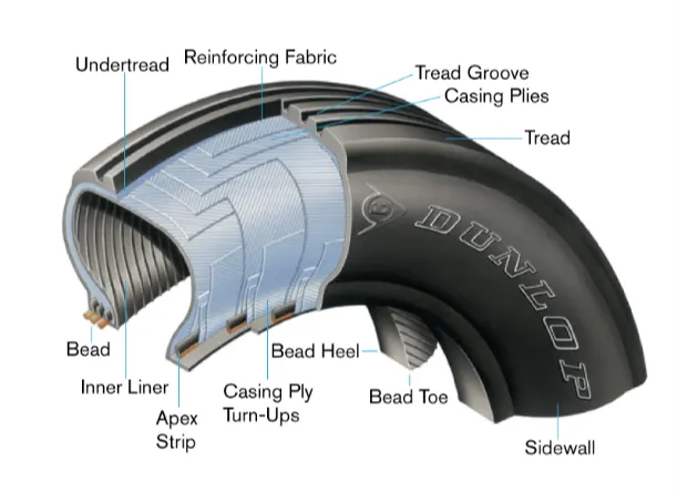
- The bias ply tyre consists of casing plies running diagonally at approximate right angles to one another.
- The number of plies and the angles at which they are laid dictate strength and load capacity.
- High-performance bias aircraft tyres feature inter-tread reinforcing fabric (ITF). This provides additional high-speed stability,reduces tread distortion under load, protects the casing plies from damage and can act as wear indicators on retreadable tyres.
Radial Tyre:
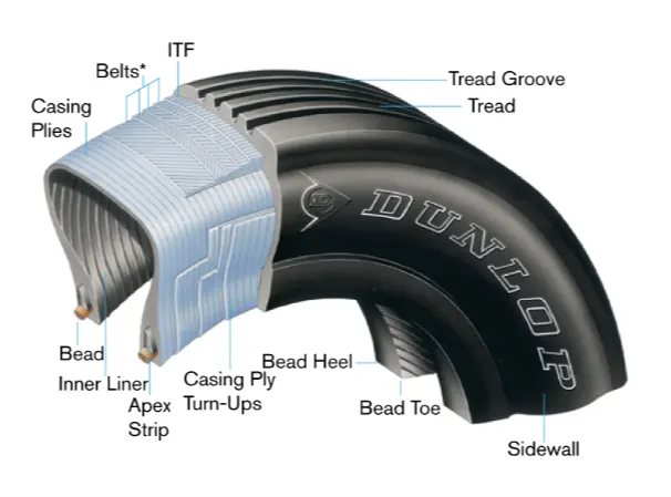
Radial tires are the most modern design of aircraft tyres. It is a design that is similar to that of car tyres.
- Typically, the radial tyre offers more landings per tread and lighter weight than a bias tyre, though sometimes at the expense of retread lives.
- Radial aircraft tyres differ to bias aircraft tyres in that the plies all run radially from bead to bead at approximately 90° to the centre-line of the tyre. Angled belt plies are laid between the tread and the top casing ply, resulting in a flatter tread and adding strength to the tyre.
- These are some of the common types of aircraft tyres and also there are three key metrics that are used regarding aircraft tyres
Ply Rating:
- The ply rating of an aircraft tire is used to identify the maximum static rated load capacity and corresponding inflation pressure applicabl to specific operational requirements.
- The ply rating is an index of airplane tyre strength and does not necessarily correspond to the actual number of casing plies within that tyre.
Load Rating:
The load rating denotes the maximum static rated load capability of the tyre in lbs.
Speed Rating:
- The speed rating denotes the maximum rated ground speed in miles per hour to which the tyre has been tested and approved.
- These are some information about the aircraft tyres.
(iii) Rolling Resistance:
- The Rolling resistance force is mainly Experienced by the Tyre when the vehicle moves over any surface.
- The rolling resistance force is given by the expression,
Frr = urr * (m.g) ,where (m.g) is the weight in Newton and (urr) is the coefficient of rolling resistance.
- The coefficient of rolling resistance (urr) depends on many factors like the ,Tyre pressure,Tyre Temperature, Material of the Tyre,Thread pattern of the Tyre and also the Road Roughness and Liquids on the Road.
- These factors determine the rolling resistance force.
(iv) Tyre Pressure:
- The pressure generally is very high in an aircraft tire to reduce the rolling resistance and to withstand the weight. Usually it will be around 200 to 300 psi of pressure and they change based on the type of the aircraft.
- Tests of airliner aircraft tyres have shown that they are able to sustain pressures of maximum 800 psi.
- Aircraft tyres are usually inflated with nitrogen to minimize expansion and contraction from extreme changes in ambient temperature and pressure experienced during flight.
(v) Brake force while Landing:
The brake force while landing is done by three different process and they are,
Aircraft disc brakes:
Aircraft has disc rotors in the landing gear, used to brake the wheels while touching the ground. These brakes are operated hydraulically or pneumatically.
Thrust reversers:
Thrust reversers allows thrust from the engines to be used to slow the aircraft. This is also very effective in bringing down the speed of the aircraft. By using a negative angle plane, we are turning the wind that is coming into the propeller to flow in the opposite direction
Air Brake:
Air brake dedicated flight control surface that work by increasing the drag force, air brakes are designed to increase drag while making little change to lift, resulting in a higher stall speed.
These are some of the types of braking methods used to bring down the aircraft's speed while landing
_______________________________________________________________________________________________________________________________________
Question.No.6:With necessary assumptions, calculate the force and power required to push / pull an aircraft by a towing vehicle.
For this question, the Towing vehicle considered is KAMBLAR Tow tractor TBL 190 and the aircraft considered is Airbus A319 TBL 190 is designed for pushback and maintenance towing of aircraft from MD-80/A319 up to B777/A340.
Length: 8,100 mm
Width: 3,450 mm
Height: 2,050 mm
Thus, frontal area is calculated to be: 7.07m2
Dry weight: 15,150 kg
Working speed: 23 km/h, 30 km/h (14.3 mph)
The Airbus A319 has the following specifications:
Length 33.8m
Wingspan 35.8m
Height 11.8m
Maximum take-off weight 64,000 – 75,500 kg
Weight of Aircraft 35,400 kg
Drag Coefficients (Cd): Taxing: 0.031
Take-off: 0.024
Landing: 0.017
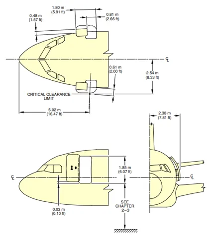
The frontal area for the Airbus A319 can estimated as
Area = (Width)*(Height)
= (2*2.54)*(2*2.38)
= 24.18m2
The fronal area of the wings can be estimated to be
Area = Width*Height
(35.08-(2*2.54))*(0.3)
=30.72*0.3
=9.2118m2
Hence, the total frontal area to be considered for the aircraft and tow truck will be
=Frontal Area of tow truck + Frontal Area of Aircraft
= Frontal Area of tow truck + (Frontal Area of Wings + Frontal Area of cabin)
= 7.07 + 9.2118 + 24.18
total frontal area=40.46m2
The forces to be taken into consideration while calculating the traction power required are
- Rolling resistance force ,Frr = μrr mg
Where, Frr is the Rolling Resistance Force in N
μrr is the Coefficient of Rolling Resistance
m is the total mass of vehicle in kg
g (g=9.81) is the acceleration due to gravity in m/s2
- Fad =`0.5rhoAc_dV^2`
Where, Fad is the Aerodynamic Drag Force in N
is the Air Density
A is the Frontal Area of vehicle in m2
Cd is the Drag Coefficient
V2 is the velocity in m/s
- Hill climbing force ,Fh = mg sin(Ψ)
Where, Fh is the Hill Climbing Force in N
Ψ is the Hill Climbing Angle in radian
- Fa = ma
Where a is the acceleration of the vehicle in m/s2
The summation of all the forces multiplied by the vehicle velocity will give the required power.

Simulation file link:
https://drive.google.com/file/d/1x0FEZ6CLZ-ueoBi96Of5LqrWpvNZcsd8/view?usp=sharing
Result:
From the above simulation the total forces and power required to tow the air craft is calculated as 37.65KN and 261.6KW respectively.
_______________________________________________________________________________________________________________________________________
Question.No.7A: Design an electric powertrain with type of motor, it’s power rating, and energy requirement to fulfill aircraft towing application in Simulink. Estimate the duty cycle range to control the aircraft speed from zero to highest. Make all required assumptions. Prepare a table of assumed parameters. Draw a block diagram of powertrain.
Block Diagram of Powertrain:
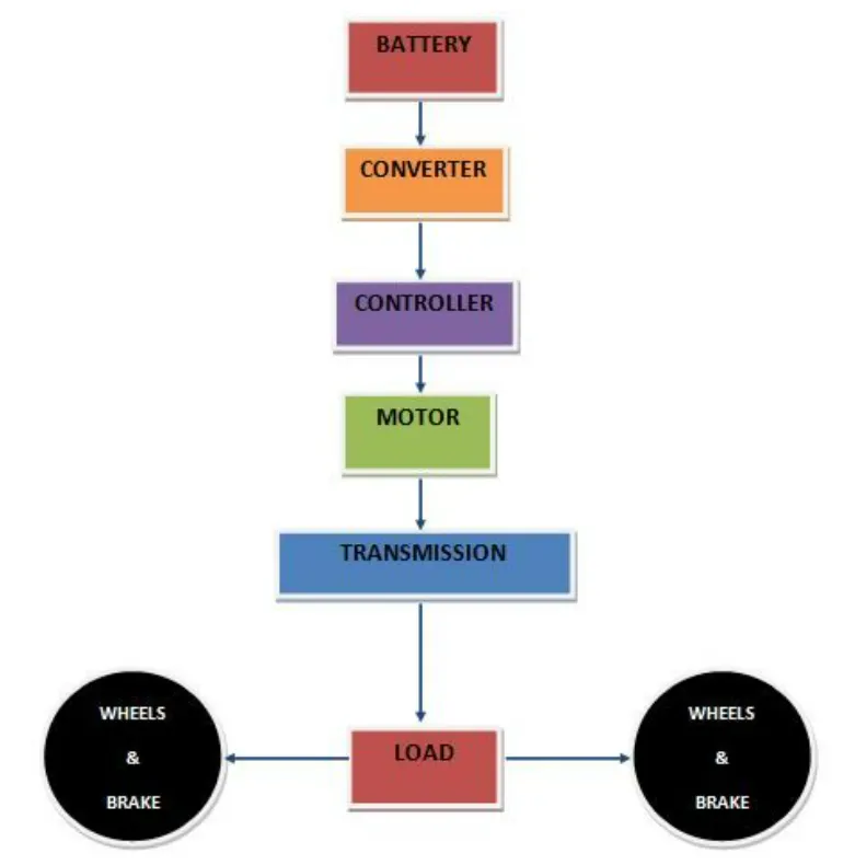
Based on the calculations done in 6A.
Force required to push/pull the aircraft =37.65KN
Power required =261.6KW
Let us assume,
The Radius of the Tyre for the Tug - 25inches =0.635m
Gear ratio=8
Transmission Effeciency (nt) =87%
Motor Efficiency (nm)=95%
then,
Torque required for the wheels (Tw)=Total Force *Radius in meters
=37.65*0.635
=23.907KNm
Motor Torque-Wheel torque/(Gear ratio*nt)
=23.907/(8*0.87)
=3.434KNm
For nm =95%. The required motor Torque (Tm)= 3.434/0.95 =3.615KNm
Similarly. The total power required by the motor considering all the efficiencies (Pt) = 261.6 /(0.87*0.95)=316.515Kw
Let us assume the towing operation was done for a 15 minutes (0.25Hrs) duration.
Then, Total Energy consumed = 316.515* 0.25=79.12 KWh
If we consider the battery capacity=420 kw is used by the towing vehicle then. The duty cycle range to control the speed from 0 to
max speed (3m/s) is given as
Duty Cycle (d)= (Required Power)/ (Rated power)= 316.51/420 =0.75
Therefore the controller will be able to provide a duty cycle ranging from 0 to 75% in order to control the towing speed.
Simulink Diagram of powertrain:
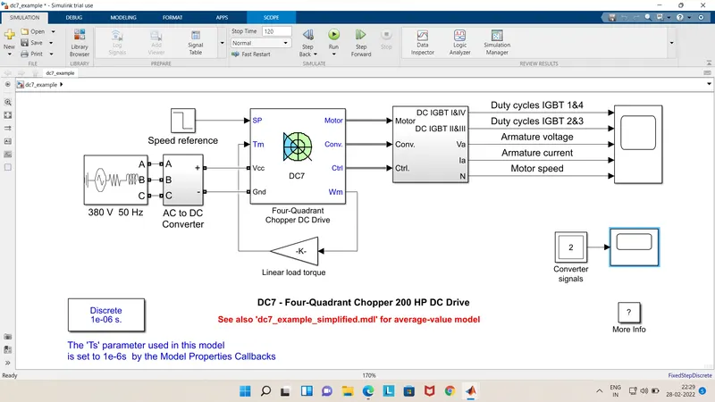
Output:
Designing the parameters in excel sheet.
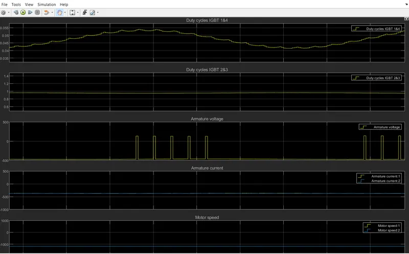
Excel Spreadsheet link:
Result:
Hence all the calculation was made in the above simulation and exceel file to tow the aircraft for 15min.
____________________________________________________________________________________________________________________________________
CONCLUSION:
Taxing & Pushback of Aircrafts using the turbine power is undesirable. Towing vehicles prove as a better alternative for that purpose. The power and energy requirements for a towing vehicle were calculated and a simple pure electric drivetrain for the same is presented.
______________________________________________________________________________________________________________________________________