Project-1: Powertrain for aircraft in runways
STUDENT OF EV BATCH 16 ONLINE COURSE
1.Search and list out the total weight of various types of aircrafts.
Weight of an aircfraft has a huge role in its performance.
Total weight is the maximum take off weight.
| Aircraft | Empty Weight | Max Fuel Weight | Max Cargo Weight | Max Gross Takeoff Weight |
|---|---|---|---|---|
| Antanov AN-225 | 628,000 lbs 285,000 kg |
661,400 lbs 300,000 kg |
417,000 lbs 190,000 kg |
1,411,000 lbs 640,000 kg |
| Airbus A380-800 | 611,000 lbs 277,000 kg |
560,000 lbs 254,000 kg |
185,000 lbs 84,000 kg |
1,268,000 lbs 575,000 kg |
| Boeing 747-800 | 485,300 lbs 220,100 kg |
427,400 lbs 194,000 kg |
295,000 lbs 134,000 kg |
987,000 lbs 447,700 kg |
| Airbus A340-500 | 370,000 lbs 168,000 kg |
386,300 lbs 175,000 kg |
119,000 lbs 54,000 kg |
820,000 lbs 372,000 kg |
| Boeing 777-300ER | 370,000 lbs 168,000 kg | 320,800 lbs 145,500 kg | 148,000 lbs 67,100 kg |
776,000 lbs 352,000 kg |
| Boeing 787-10 | 299,000 lbs 135,500 kg | 223,500 lbs 101,500 kg |
126,300 lbs 57,300 kg | 560,000 lbs 254,000 kg |
| Boeing 737-900 | 98,500 lbs 44,700 kg |
53,100 lbs 24,000 kg |
44,600 lbs 20,200 kg |
187,000 lbs 85,000 kg |
| Airbus A320-100 | 93,900 lbs 42,600 kg |
48,700 lbs 22,100 kg |
44,000 lbs 20,000 kg |
150,000 lbs 68,000 kg |
| Embraer 190 | 63,500 lbs 28,800 kg |
28,600 lbs 13,000 kg |
28,800 lbs 13,100 kg |
106,000 lbs 48,000 kg |
| Gulfstream G650 | 54,000 lbs 24,500 kg | 48,200 lbs 21,900 kg | 6,500 lbs 3,000 kg |
100,000 lbs 45,200 kg |
| Bombardier CRJ900 | 48,160 lbs 21,850 kg | 19,600 lbs 8,900 kg | 6,075 lbs 2,760 kg | 80,500 lbs 36,500 kg |
| Bombardier Q400 | 39,300 lbs 17,800 kg |
11,700 lbs 5,300 kg |
18,700 lbs 8,500 kg |
62,000 lbs 28,000 kg |
| Learjet 75 | 13,900 lbs 6,300 kg | 6,060 lbs 2,750 kg |
2,900 lbs 1,300 kg |
21,500 lbs 9,700 kg |
| Cessna Citation CJ4 | 10,300 lbs 4,700 kg | 5,800 lbs 2,650 kg |
2,200 lbs 1,000 kg | 17,200 lbs 7,800 kg |
| Beechcraft King Air B100 | 7,100 lbs 3,200 kg | 3,200 lbs 1,450 kg |
4,150 lbs 1,900 kg |
12,000 lbs 5,400 kg |
| Diamond DA50 RG | 3,200 lbs 1,450 kg |
340 lbs 155 lbs |
1,250 lbs 560 kg |
4,400 lbs 2,000 kg |
| Beechcraft Bonanza G36 | 2,500 lbs 1,150 kg | 450 lbs 200 kg |
850 lbs 385 kg |
3,660 lbs 1,660 kg |
| Cessna 206H | 2,200 lbs 990 kg |
520 lbs 235 kg |
1,150 lbs 520 kg |
3,600 lbs 1,630 kg |
| Sirrus SR22 | 2,250 lbs 1,000 kg | 485 lbs 220 kg |
950 lbs 430 kg |
3,600 lbs 1,630 kg |
| Cessna 172R | 1,700 lbs 770 kg |
380 lbs 170 kg |
560 lbs 255 kg |
2,425 lbs 1,100 kg |
2. Difference between ground speed and air speed.
Ground speed: It is the airplane's relative speed with the surface of the earth.
True air speed : The speed relative to the air it is flying in.
Ground speed vs air speed.
- True air speed is also the speed at which the air is flowing around the aircraft's wings.
- Ground speed is the aircraft's speed relative to the ground.
- Ground speed is horizontal, i.e., an aircraft climbing completely vertically will have zero ground speed.
- Air speed is what that determines whether there is enough airflow around the aircraft to make it fly.
- While ground speed determines how fast an aircraft will get to its destination.
Ground speed is the summation of airspeed and wind speed.
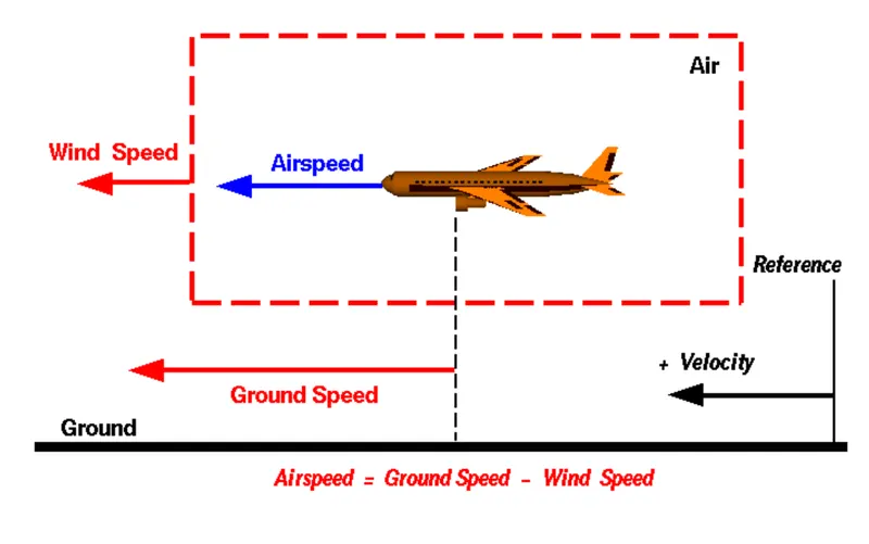
If an aircraft is flying in the same direction as the wind is blowing, the aircraft experience tailwind and its gorund speed is higher than air speed.
If the wind is blowing against the direction the aircraft is travelling in, the aircraft experience headwind, and its ground speed is lower than air speed.
3. Why is it not recommended to use aircraft engine power to move it on the ground at Airport?
Aircraft can move using their engine thrust in the airport apron and taxiways but the thrust produced by the aircraft engine will have series impact on the airport terminal buildings and infrastructure.
Major issues with usage of aircraft engine on the ground of the airport are:
- The engine may blow the sand debris close to the engine and may suck in to the engine causing serious damage to the aircraft engines.
- Aircraft can lose control in the ground causing serious damages.
- There is a serious safety threat to the ground staffs on the airport ground.
- The aircraft engines being loud, one or more aircrafts running simultaneously can result in severe noise pollution and can impact passenger health.
- Also engine running in ground can result in huge fuel consumption.
To avoid this airports have been using various methods like pushback to move aircraft away from the gate. This will save fuel cost for the aircrafts and safety for ground staffs.
4.How an aircraft is pushed to runway when its ready to take off?
There are two methods to push aircraft to runway.
1. Taxiing: It is the movement of aircraft on the ground under it's own power in contrast to towing or pushback where the aircraft is moved by a tug. The aircraft usually moves on wheels, but the term also includes aircrafts with skis or float.
An aircraft uses taxiways to taxi from one place on an airport to another.
2. Towing: Movement of large aircrafts in airports, flight lines and hangar is done by towing with a tow tractor.
In case of small aircrafts, movement is done by hand pushing at the correct place of aircrafts.
Towing an aircraft can be a hazardous operation, it could lead to damage of aircrafts and injury to personnels when it is done carelessly.
Also when an aircraft is ready to take off, the following procedure is followed
- The apron handler removes the chocks.
- A so-called pushback truck reverses the aircraft into taxiing position, pushing it with a towbar attached to the nose-wheel strut. Or, in the most modern versions, by actually lifting the wheel. That speeds up coupling and decoupling.
- The aircraft taxis to the runway to depart at the agreed time.
5.Learn about take off power, tyre design, rolling resistance, tyre pressure, brake forces when landing.
Take off power
- The amount of power that an engine is allowed to produce for a limited period of time for takeoff.
- The use of takeoff power is usually limited to 5 min for reciprocating engines and up to 2½ min for gas turbine engines.
- This may not always be the case. Specifically, with respect to reciprocating engines, it is the brake horsepower developed under standard, sea-level conditions and under the maximum conditions of the crankshaft rotational speed and the engine manifold pressure approved for the normal take-off.
- It is limited in continuous use to the period of time shown in the approved engine specifications.
Take off performance can be predicted using simple measure of acceleration of the aircraft along the runway based on the force equilibrium
The force involved
T= Thrust of propulsion system pushing aircraft along runway
D= aerodynamic drag of vehicle
F= Rolling resistance friction
dv/dt = (T-D-F)/m
m is the mass of the vehicle
dv/dt is the acceleration along the runway.
Tyre design:
The tyre of the aircraft is designed to withstand heavy loads while landing, take off, taxing and parking.
The number of the wheels required for an aircraft increases with weight of the aircraft.
During landing aircraft tyre generates more heat.
Aircraft's tread pattern is designed to facilitate stability in high crosswind conditions, to channel water away to prevent hydroplaning and for braking effect.
There are two types of tyre construction
a)Radial tyre:
- It has fibre strands of ply fabric oriented at 90 degree to the direction of rotation and the tyre sidewall.
- This restricts bidirectional flexibility and the flexibility of sidewall while it strengthens the tyre to carry heavy loads.
- Most radial tyres are resistant to penetration and cuts.
- Due to stiffer treads they distribute weight evenly. Thus providing greater traction.
b)Bias-ply tyre:
- It has fabric bias oriented with and across the direction of rotation and the sidewall.
- Since fabric can stretch on the bias, the tyre is flexible and can absorb loads.
- Tyre strength is obtained by adding plies.
- These tyres donot offer as much smoothness in terms of riding quality.
Rolling resistance:
- It is also called as rolling friction or rolling drag
- It is the force resisting motion when a body rolls on a surface.
- It is mainly caused by non elastic effects.i.e., not all the energy needed for deformation of wheel is recovered when the pressure is removed.
- There are two forms, hysterisis losses and permanent plastic deformation of the object or the surface.
- Another cause of rolling resistance is slippage between wheela and the surface which dissipates energy.
Rolling resistance force = Urr x m x g.
- In comparison with sliding friction, rolling resistance is often expressed as a coefficient of sliding friction.
- The coefficient of rolling friction(Urr) is generally much smaller than the coefficient of sliding friction.
Factors that contribute to rolling resistance are
- Amount of deformation of wheels.
- Deformation of roadbed surface and movement below the surface.
- Wheel diameter, load on the wheel, surface adhesion, sliding, and relative micro-sliding between the surfaces of contact.
Tyre pressure:
Aircraft tyres operate at high extremes of pressure, load and speed.
Maintaining proper tyre inflation is necessary to prevent tyre related events.
- Aircrafts are usually inflated with nitrogen to minimize expansion and contraction from extreme changes in ambient temperature and pressure
- Dry nitrogen expands at the same rate as other dry atmospheric gases, but common compressed air sources may contain moisture which increase expansion rate with temperature.
- Use of inert gas for tire inflation eliminates the possibility of tire explosion.
Rolling resistance and tyre pressure have an inverse relation between each other.
Brake forces when landing
Aircraft brakes stop a moving aircraft by converting its kinetic energy to heat energy by means of friction between rotating and stationary discs located in brake assemblies in the wheels.
Brakes provide the critical stopping function during landings to enable airplanes to stop within the length of the runway.
Aircraft brakes work in conjunction with other brake mechanisms such as thrust reversers, air brakes and spoilers.
Thrust reversers are surfaces that are deployed into the path of the jet blast from the engines to redirect propulsive thrust in a direction that opposes the motion of the aircraft.
Air brakes and spoilers are flight control surfaces that create additional aerodynamic drag when deployed into the path of air flowing around the aircraft.
6.A. With necessary assumptions, calculate the force and power required to push / pull an aircraft by a towing vehicle.
The force required to push/pull an aircraft by towing vehicle are rolling resistance and aerodynamic drag force.
The data is from towing truck TMX-150-9 and Aircraft Airbus A319.
Data:
Mass of the truck = 8300kg
Mass of the aircraft = 75500kg
Length of the aircraft = 33.84m
Velocity of the truck = 25kmph
Height of the aircraft = 11.76m
Air density (rho) = 1.225kg/m^3
Drag coefficient(Cd) = 0.75
Rolling resistance coefficient = 0.013
Gravitational constant = 9.8Nm
Rolling Resistance force(Frr)
Frr=μrr*m*g
m= mass of the truck + mass of the aircraft = 8300+75500 =83800kg
Frr = 0.013*83800*9.8 = 10678.12Nm
Aerodynamic drag force(Fad)
Fad = 0.5*ρ">ρ*Cd*A*V^2
V = velocity of the truck in m/s = 25*(5/18) = 6.95m/s
Area(A) = Length of the aircraft * Height of the aircraft = 33.84*11.76 = 397.95m
Fad = 0.5*1.225*0.75*397.95*6.95^2 = 8830N
Total force required to push or pull an aircraft by towing vehicle is
Ftotal = Frr+Fad = 10678.12+8830 = 19508.12N
Total power = Ftotal*Velocity =19508.12*6.95 = 135.581kW.
B.Develop the model for the calculated force and power using Simulink.
The simulink model for the above calculated force and power is
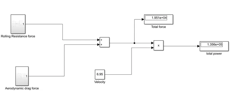
Total force = Frr +Fad
Total power = total force x velocity
The simulink model for rolling resistance force is
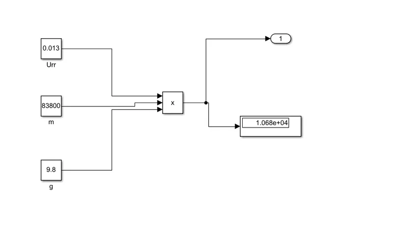
Frr= Urr*m*g
The simulink model for aerodynamic drag force is
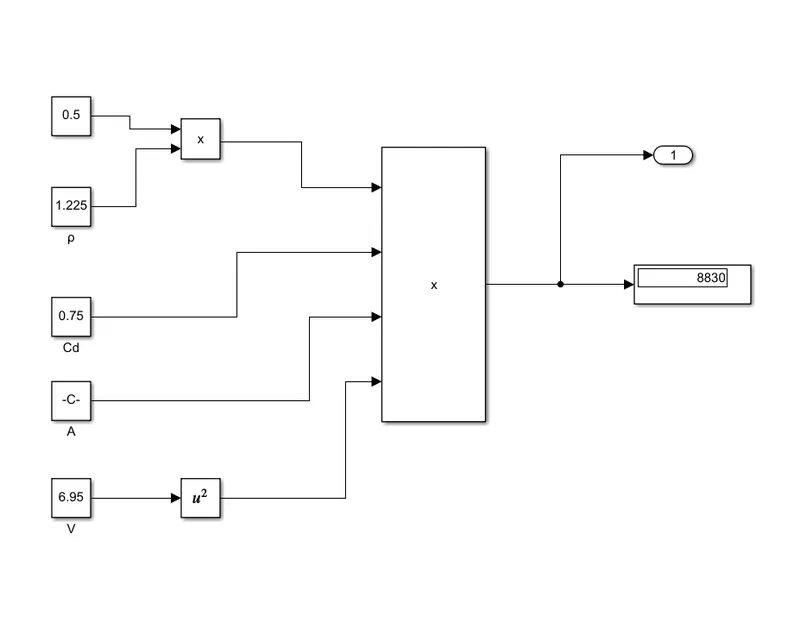
Fad= 0.5*rho*Cd*A*V^2
Thus simulink model for total power and force have been formed.
7.A.
Design an electric powertrain with type of motor, it’s power rating, and energy requirement to fulfill aircraft towing application in Simulink. Estimate the duty cycle range to control the aircraft speed from zero to highest. Make all required assumptions. Prepare a table of assumed parameters. Draw a block diagram of powertrain.
(Hint :DC7 Block)
Block diagram representation of electric powertrain is given below
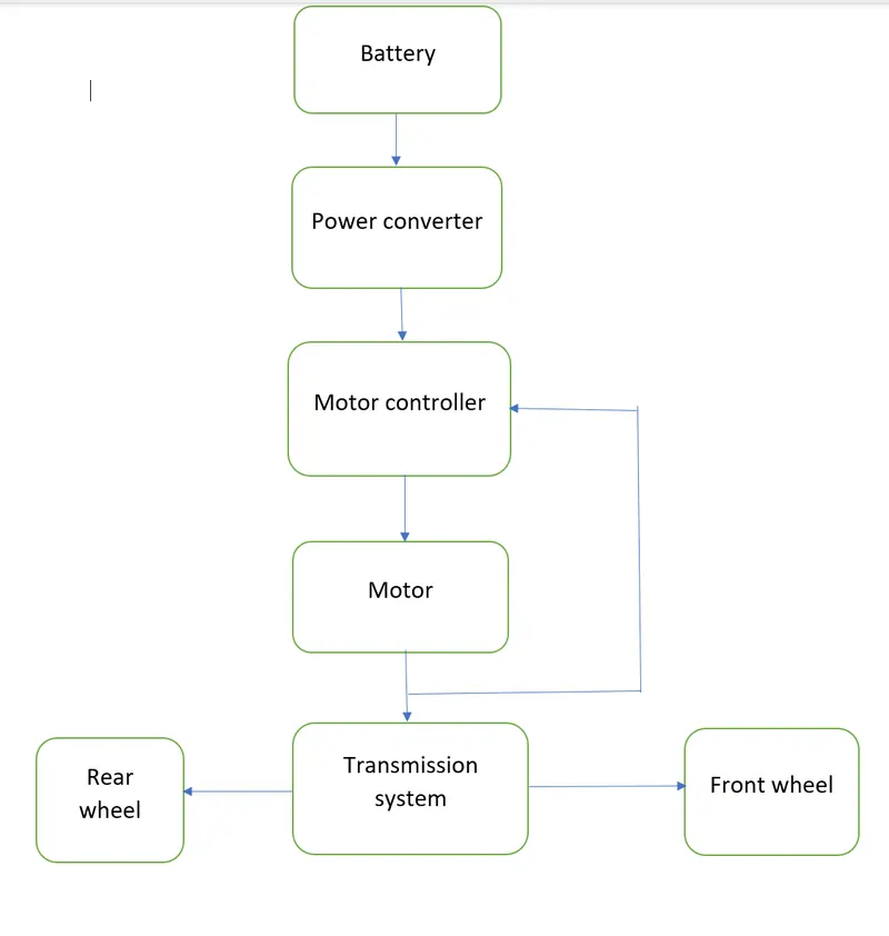
Designing a electric power train aircraft towing application
The tyre specification of TMX-150-9 is 315/70 R15
Datas:
Force required to tow the aircraft = 19508.12N
Power required for towing the aircraft = 135.581kW
Tyre radius = Aspect ratio x section width + (Rim diameter/2) = 0.411m
Gear ratio = 7
Transmission efficiency(ηt) = 80%
Motor efficiency (ηm) = 92%
Calculations
Torque required at the wheels(Tw) = Total force xTyre radius = 19508.12*0.411 = 8017.83Nm
Actual power required (Pac) = Power required/(ηt*ηm) = 135.581/(0.8*0.92) = 184.21kW
Motor power rating should be close to 190kW
Motor Torque Tm=Tw/(gear ratio*ηt) = 8017.83/(.8*7) = 1431.75Nm
Actual motor torque (Tmac) = Tm/ηm = 1.431/.92 = 1.555kNm
Battery capacity
Towing time = 15 mins = 0.25hours
Battery capacity = Pac*hours = 184.21*.25 =46.05kWh
Should use 210kW battery for running tow truck easily.
Duty Cycle = (Pac/input power) = 184.21/210 = 0.87
Simulink model of towing truck
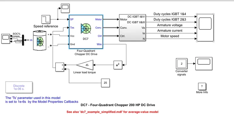
Here DC7 four quadrant chopper is used.
The AC input supply has been replaced by a battery source which is DC.
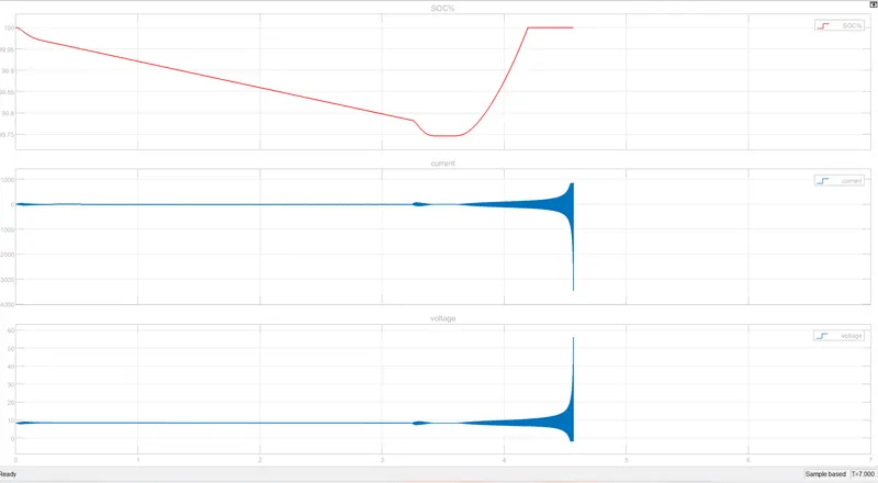
The SOC, current and voltage has been monitored with the help of scope.
In the end the duty cycles of IGBT 1&4, IGBT 2&3, armature voltage, armature current and motor speed have been monitored with the help of scope.
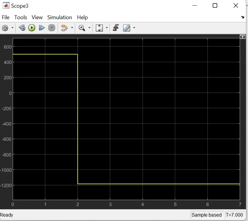
The input waveform from speed reference is
The battery SOC, current and voltage waveform
The output obtained is
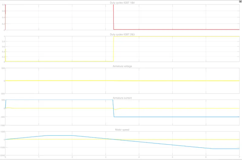
The above results are for simulation of DC7 block which is run for 7 sec.
B.The design in excel sheet