Project-1: Powertrain for aircraft in runways
1. Search and list out the total weight of various types of aircrafts.
An average airplane weighs around 90,000 pounds (41,000 kilos) empty weight, which means the weight of the airplane when its fuel tanks are empty and there are no people or luggage on board. This example is for a B-737-800 aircraft which is considered a medium-sized commercial jet airliner.
You can expect to add 84,000 pounds (38,000 kilos) of fuel, passengers, and baggage to that number to get a maximum takeoff weight of 174,000lbs (79,000 kilos)
Obviously, these numbers depend dramatically on the type of aircraft you are referring to. I will show you 13 examples of different airplane weights in this article for you to reference. As a general rule, you can expect most airliners to weigh about 1350 pounds per foot length.Again using the 737-800 as an example.
Here are a few examples of common aircraft and how much they weigh
- Cessna 172 – Used by many as initial training aircraft (27 feet long) – 1450lbs empty weight, 2450lbs max weight
- Citation Jet M2 – (42 feet long) – 6990lbs empty weight, 10,700lbs max weight
- Boeing 767-300 – (185 feet long) – 195,000lbs empty weight, 400,000 max weight
- Boeing 787-800 – (186 feet long) – 264,500lbs empty weight, 502,500lbs max weight
- Boeing 777-300 – (242 feet long) – 354,000lbs empty weight, 660,000lbs max weight
- Boeing 747-400 – (232 feet long) – 407,000lbs empty weight, 910,000lbs max weight
- Airbus A320 – (123 feet long) – 82,000lbs empty weight, 170,000lbs max weight
- Airbus A330 – (210 feet long) – 274,500lbs empty weight, 507,000lbs max weight
Classifications Of Aircraft:
Aerostats (Lighter Than Air): Aerostats or lighter than air aircrafts are very more lightweight in weight. These types of light aircraft generally use buoyancy like ships, which help them float in the air. Low-density gas such as hydrogen, helium, or hot air balloons is used to fill in the aircraft. This low-density gas is lighter than air, and hence the name. The most common types of aerostats known to us are hot air balloons and sky lanterns.
Aerodynes (Heavier Than Air): Alternatively, the other aircraft, heavier than air or aerodynes, as we understand, is much higher in weight and size. They push the gas or air downwards; which reaction helps to make aircraft upwards. Since these are dynamic through movements in the air, they are called aerodynes. This dynamic lift through the air can be caused mostly through mechanisms, as you must have already known.
- One is the fixed-wing classification, just like planes. In this category of fixed-wing aircraft, the entire mechanism is relied upon forward speed to create airflow all over wings.
- Another mechanism is rotorcraft, which uses spinning rotors that are like wings. The helicopter is the most commonly known aircraft under this classification.
Types Of Aircrafts In The World:
Now that we know the most common classification, categories, and subcategories under the aircrafts, let us see different types of aircrafts and a list of all aircraft with pictures.
1. Amphibious:
Amphibious aircraft, otherwise also popularly known as amphibian is a multipurpose aircraft which can work, take off and land both water and ground. They are used as both seaplanes or flying boats, or also airplanes. In this aircraft, the engine is either placed in front, or even above the wing, that is most commonly found in floatplanes, On the other hand, the modern and other amphibious aircraft have engine and propeller placed above the wings. The size of amphibians differs as per the purpose; there are military amphibians, leisure purpose seaplanes, and civil amphibious aircraft.
2. Helicopters:
Helicopter aircraft, also known as a chopper, is commonly known to most of us and belongs to rotorcrafts. Horizontally spinning rotors help and aid the helicopter to lift and thrust. These aircraft have the advantage of taking vertically, horizontally, and fly both backward and forward or laterally. Unlike the other fixed-wing aircraft, these benefit from taking off and land at several places and flying even in congested areas. The engine depends on the size, purpose, and function of the chopper. Today, the helicopter is mostly used for military purposes, cargo, construction, rescue, tourism, aerial observation, and the government. The size of the chopper hence mostly depends on the usage.
3. Multi-Engine Piston:
As the name suggests, Multiple or Multi-engine piston aircraft has more than one single-engine, unlike the other categories and types of aircraft. These multi-engine pistons are known to have a second power source, which is greatly helpful during another engine’s failure. Due to this multiple power and engine facility, the aircraft-quality, capacity, speed, and climb rate is much higher than the usual air crafts. In most cases, this kind of aircraft is used by air service for their services and duties.
4. Biplanes:
Biplanes come under the category of fixed-wing aircraft. In this category, two wings come one above each other on both sides. This kind of plane is among the first aircraft to discover fixed-wing planes. The biplanes have lower weight but with excellent stiffness and efficiency. The biplanes are fitted with reciprocating engines. Only two adults, in most cases, can do these. In most cases, biplanes are spotted and used for army and military purposes of specific countries. These aircraft were among the most commonly used ones during world war times.
5. Balloons:
The balloon type aircraft are standard aircrafts most of us are aware of and are mostly spotted during tourist activities. It comes under a kind of aircraft that floats in the sky and is much different from other airships and aircraft categories. While most confuse them with airships, the balloons are distinct in that they do not possess any engine and cannot change their direction, except for up and down. The balloon’s top is called an envelope, and the bottom part is a basket where people can sit. The most common ones in the category of balloons are hot air balloons.
6. Gliders:
Gliders come again under the category of fixed-wing aircraft. The types of gliders aircraft are used through air reaction against lifting surfaces and mostly do not use any engine. Although small engines may be used as required (in cases like a motor glider), most glider aircraft are efficient for self-take without engines. A wheeled undercarriage helps in take-off or landing. In the past, gliders are used for military purposes and wars; however, nowadays, we even see them in tourist activities and entertainment or leisure. The most common types in this category include hand gliders and paragliders. Most gliders are small in size and can fit a maximum of two people.
7. Gyroplanes:
Gyroplanes, also known as autogyro or gyrocopter, is a rotorcraft aircraft category that uses rotor machines to lift. They are similar to helicopter in appearance, although a bit narrow, and have an engine-driven propeller. The air flows help the gyroplanes lift upwards, and the rotor self-propels as per the way air flows through it. While gyroplanes or autogyros are mostly used for military and war purposes during the 20th century, nowadays, they are spotted in Olympics and police departments at some states.
8. Parachutes:
Parachutes are the most common types we often hear and see. They are slow-moving air flowing craft that helps move through, creating drag to land. They are made through lightweight yet stable and fitting fabric such as nylon or silk. Most parachutes may be in the shapes of round, dome, or inverted dome. Although most parachutes are spotted during leisure activities and entertainment, they are also used and deployed by state and operations during expeditions to ice areas such as polar ends. Only one or two maximum can fit in one parachute.
9. Single Engine Piston Aircraft:
Like the multi-engine piston plane, we have seen earlier. This aircraft uses only one engine. These aircraft are used for shorter distance works and not for heavy works. They can access smaller runways, takes less space, and has lesser climb and speed. Most single-engine pistons can fit only four to six people, depending on the plane and size.
10. Tricycle Gear Aircraft:
The tricycle gear aircraft is a kind of plane that has tricycle fashion fixed landing gear. The arrangement has a nose wheel in the front and two more in the main wheels. These are lightweight and are known to have better visibility of the ground, and is very easy to take off and land. The aircraft also has significantly less drag and allows the application of a full brake. They are used for lighter and quick uses, given the advantages of easy runs.
11. Business Jets:
Business or private jet aircraft are known to be among the luxurious or unique aircraft to transport and fly a small group of people, even individuals. While they are costly due to their design, plush appearance, and very sophisticated looks, the business jets are used by different classes of people – from government officials to armed forces for special operations to companies and private ownership. While the speed, engine, and other manufacturing are similar to airplanes, the size differs from lightweight or small jets to mid-sized ones to long business jets. The heavy and long jets can accommodate 16 to 18 people, whereas the mid-size (depending on the capacity) can accommodate up to 12 or 10 people. The smaller types of business aircraft are only for four to six individuals.
12. Taildraggers:
Taildraggers, also known as tail-wheel type gear draggers, consists of two main wheels at the forward size and a small-sized wheel to skid near the tail area. These are the conventional aircraft variety which uses such gear draggers instead of the modern tricycle propeller aircraft. These are the much lighter size and weight aircraft and can even be operated in skis. However, they have very poor visibility on the ground and are difficult during heavy wind conditions.
13. Tiltrotors:
Tiltrotors use powered rotors for propulsion and to generate lift. These powered rotors, also called proprotors, are added to rotating shafts of a fixed-wing. These use transverse rotor design and combines the vertical lift capability of a helicopter. The rotors, similar to the chopper, helps lift this aircraft. However, the propulsion is much more efficient and can avoid retreating blade stall, commonly seen in choppers. The speed and range are heavier and higher than a normal helicopter and almost near a fixed-wing aircraft. The altitude capability of tiltrotors is higher than helicopters.
14. Light-Sport Aircraft:
The light-sport aircraft, also known as LSA, differs from country to country. However, they are into the new category of small and very lightweight aircraft. These are super simpler to fly. Although they may be a bit heavier than ultralight aircraft, they are sophisticated, looks grand. These are two-seater versions and are much affordable too.
15. Turboprops:
As the name suggests, turboprops or turboprop aircraft have gas turbine engines connected to the gears to turn the propeller to move them through and around the air. They burn much lesser fuels and have lesser operating costs too. These types of turboprops are larger than piston aircraft and can carry more passengers. These also fly high and can go to an altitude of 35000 feet. However, they are slower in speed than jet planes. The turboprops size varies according to the need and can fit a small set of people or up to eight or ten at maximum.
16. Floatplanes:
The floatplanes are similar to seaplanes, which floats on water through the floats mounted under the fuselage. These mounts are added instead of the undercarriage, where wheels are placed in other planes. These do not have landing gear, which makes it possible to land, in which case it becomes similar to amphibious aircraft (as seen earlier). Seaplanes or floatplanes are heavily used during world war times for military operations; however, now is witnessed more of a pleasure flight in many countries.
17. Fighter jets:
Fighter jets, also known as a fighter or fighter aircraft, is military particular fixed-wing aircraft. They are designed only to use for combatting air to air fights against other aircraft. They have very high speed, manufactured for use against air attacks only. However, few fighters have a second capacity to use for ground attacks, too, in which case they are known as fighter bombers. There are several categories in the fighters: light fighter, heavy fighter, interceptor, night fighter, all-weather fighter, and more. With the help of technological advances and breakthroughs, today’s fighters have numerous other capacities and innovations such as data transmissions, sensors, secure cockpits, high bandwidth, and more.
18. Cargo planes:
Cargo aircraft or cargo planes are also known as freight aircraft, airlifter, or cargo jets. These are the fixed-wing classification of aircraft known only for carriage or cargo instead of individual passengers. These cargos are specially built only for lifting carriages and do not have amenities for fitting people or passengers. They have wide doors and facilities to protect and provide shipment. Unlike usual passenger jets, the high-wings presence allows to preserve and make the cargo sit near the ground. The number of wheels is also more in cargo jets. These cargo aircraft can be used both for civil purposes as well as military usage.
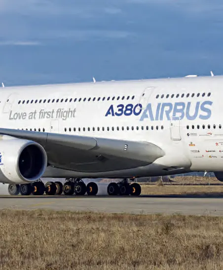
The world’s largest passenger airliner is the Airbus A380. Its maximum takeoff weight is over a million pounds!
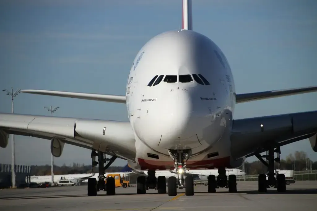
Airbus A380 – (240 feet long) – 610,700lbs empty weight, 1,234,600lbs max weight
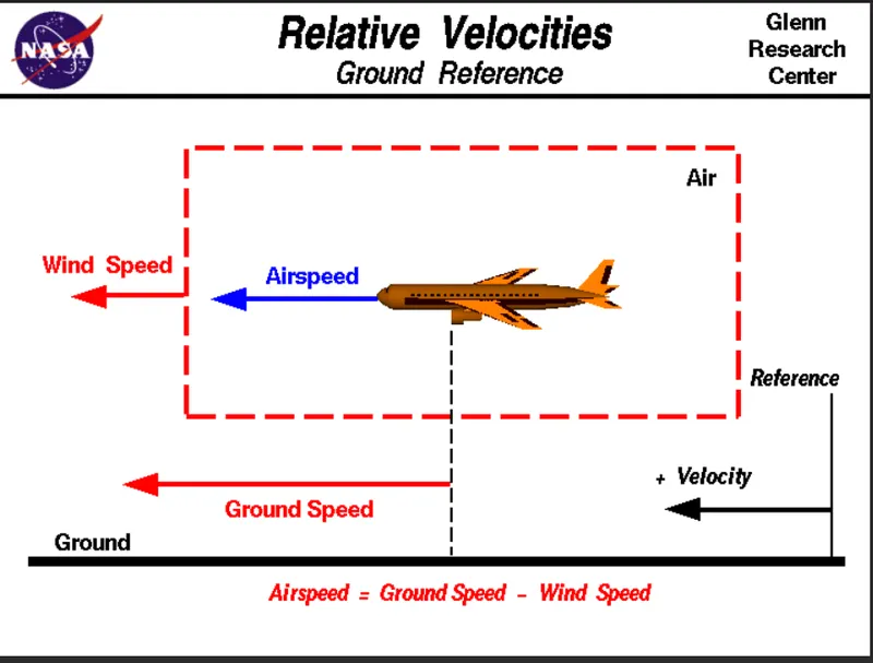
2. Is there any difference between ground speed and air speed?
There are two speed will come in picture for airplane take off-ground speed & airspeed.while the ground speed is the airplane relative to the surface of the earth ,airspeed at least true airspeed-is its airspeed at least true airspeed-is it speed relative to the air it is flying in,true air speed is simply the speed at which the aircraft is moving relative to the air is flowing around the aircraft's wing.
Ground speed,is the aircraft relative speed to the ground.one thing that should be noted here is that it's its horizontal rather than vetical speed-an aircraft climbing completely vertically would have a ground speed of zero.while airspeed is what determines whether there is enough airflow around an aircraft to make it fly,ground speed is what determines how fast am aircraft will get to its destination
3. Why is it not recommended to use aircraft engine power to move it on the ground at Airport?
For moving the planes in the aircraft ground with aircraft engine power is highly risk will damage the terminal building or equipments,which may cause engine ground running related potential losses,& human mistake loss of control or lack in guidance may cause the damages.
For moving the aircraft in ground requires proper guidance ,without other planes or equipments it has to be done.in most of cases persons will be holding the specific company issued approval for the requires tasks of moving the aircrafts,consquences of loss in control during taxi or towing are same as apply to these operations generally it is concerened with risks arising from the static running of one or more aircraft engines.this unwanted consequences from such static running are mainly related to those arising from the uninteneded ,ovement of the aircraft during engine running - effectively a loss of control especially during the high power engine running.Damage occue to aircraft itself other neraby too .there is a risk of injury to ground support personnnel who may be in relatively close proximity to aircraft.
4. How an aircraft is pushed to runway when its ready to take off?
| Lights | Meaning |
|---|---|
| Flashing green | Cleared to taxi |
| Steady red | Stop |
| Flashing red | Taxi clear of runway in use |
| Flashing white | Return to starting point |
| Alternating red and green | Exercise extreme caution |
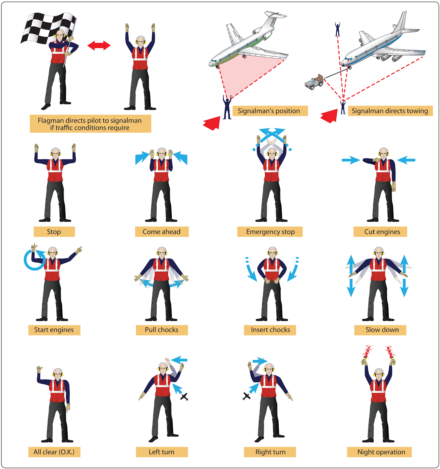
Taxi Signals
 |
Airplanes turn on the ground/runway by turning the nose wheel in the front. Bigger airplanes usually use a tiller – a type of steering wheel – to turn the nose wheel, while smaller planes turn using the rudder pedals. Other steering techniques include differential braking and differential thrust.
Taxi signals are usually given at night with the aid of illuminated wands attached to flashlights. Night signals are made in the same manner as day signals with the exception of the stop signal. The stop signal used at night is the “emergence stop” signal. This signal is made by crossing the wands to form a lighted “X” above and in front of the head.
Airplane steering methods
It is essential to understand the different techniques used to taxi an airplane on the ground. Pilots are often advised to maintain slow, steady movements to avoid damage on the nose wheel, which facilitates ground steering of a plane.
There are three methods involved in taxiing an aircraft:
Nose wheel steering
This is the popular airplane taxiing method used in virtually all aircraft. Nose wheel steering can be accomplished on either side using a rudder pedal or steering handle (tillers). Different sizes of planes implement nose wheel steering in different ways:
- Small planes usually use the rudder pedal, which is connected to the nose wheel via a mechanical linkage.
- Larger aircraft rely on the steering handle, which uses a hydraulic system to turn the nose wheel either direction.
Differential Braking
Differential braking is a popular steering technique in, among others, fighter aircraft. In this system, the nose wheel remains free, and turning is achieved by unequal braking of the left and right main wheels. It’s often used in small planes to make sharp turns and requires a special technique.
Differential Thrust
This isn’t a very popular method used for steering aircraft, but it is still available for pilots of twin-engine airplanes. In this technique, the thrust provided by the two engines is varied, causing the plane to shift right or left.
Making an airplane turn on the ground
Taxiing an airplane requires extreme caution and awareness at all times. There are various turns pilots can make. Some of the popular turns include:
Straight ahead turn
Straight ahead turns that involve a slight change in direction are often accomplished using the rudder pedals, which are operated by the pilot’s feet. The pilot steps on the rudder pedals, which are linked with the nose wheel, and can turn it in either direction.
To make a small turn to the left, the pilot presses the left pedal and the right pedal for slight shifts to the right. The top of the rudder pedals work as braking pedals, so you can push them whenever you need to slow down the plane’s speed or brake.
Making a sharp turn
While rudder pedals can make small changes in direction as needed, they aren’t designed to achieve the tighter turining radius required for making sharp turns.
For such shifts, pilots use the hand-grabbed steering handle, also known as a “tiller.” The tiller is located on a side panel by the window.
Like the rudder pedals, a tiller turns the nose wheel either direction. The pilot must have a tight grip on the tiller handle and move it to the direction they want.
Airport taxiway
Airport taxiways are designed to make takeoff, landing, and parking effortless. Virtually all runways include corners, and there are various navigation elements integrated to help pilots make turns.
A typical track will have yellow centerlines that identify where the nose wheel should remain at all times. However, each aircraft comes with unique requirements and the type of turn.
Caution is a priority when making any turns on the ground, whether during takeoff or landing. Widebody aircraft and sharp corners offer the biggest challenges for new pilots, who must be aware of the immediate surroundings, speed, and incoming communication from air traffic control. However, experienced pilots should find steering an airplane across a runway more exciting than challenging. The process often involves slowing down and using the rudder pedal, tillers, or differential braking to make different kinds of turns.
Private runways
Turning a plane on the ground in a private track requires more precaution than commercial airports. The pilot must be constantly aware of their surroundings before setting the aircraft in motion. By applying thrust (gas), you cause a blast behind the engine that is strong enough to injure people or damage any property in the way. The front area of the engine can also suck in anything that is too close during takeoff.
All airplane taxiways must have lines drawn to indicate the center alignment pilots use to keep the plane on track. If the runway is clear, turning an aircraft on a private or commercial runway involves the same techniques.
The size and plane model also play a significant role in determining the best way to make turns on the ground. Some planes require ground help to assist the pilot make safe turns.
Speed and safety
Taxiing an airplane across bent runways may seem like an effortless task for the outsider. However, the unique wheel system planes use presents various challenges that call for a combination of techniques. When turning an airplane on the ground, speed is one of the crucial elements. As a general standard, taxiing a plane should be kept under 30 KTS or 35 mph on straight runways. When approaching a turn, the plane shouldn’t exceed 12 KTS or 14 mph.
All airplanes come with a flying mannual that specifies how fast a pilot should taxi the aircraft. Airport regulations and other governing bodies can also determine the maximum speed allowed for taxiing a plane or approaching a corner. Other than speed, there are several other safety elements and measures involved when turning an aircraft on the ground.
Unlike cars, where the driver is in full control of each turn they make, the responsibility of turning an airplane on the ground extends to several other people. The pilot’s taxiing mechanics play a significant role.
However, the process still relies on air traffic ground controllers, ground (ramp) personnel, vehicles on the ground, planes within the vicinity, and more. The extended responsibility reflects the complicated nature of taxiing an airplane and making turns on the ground.
Conclusion
To recap, planes can turn on the ground using three main methods, although only two are popular among commercial aircraft. Pilots have access to various navigation tools at the cockpit, including foot-operated rudder pedals, hand-gripped tillers, and yoke steering wheel. These accessories can control the nose wheel and also regulate the speed of the airplane to make safe turns. Pilots can also choose other braking and turning techniques depending on what the coroner calls for.
A smooth curving runway, for instance, will have different requirements form sharp 90% turns. On the other hand, aircraft that don’t feature twin engines cannot use differential thrusting to make turns. For a seasoned pilot, making a plane turn on the ground is an exciting experience and less daunting than you would think. However, much like everything surrounding airplane navigation and traffic control, making a plane turn on the ground requires incredible caution and awareness at all times.
5. Learn about take off power, tyre design, rolling resistance, tyre pressure, brake forces when landing.
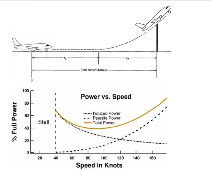
Take off power -amount of the power that an engine is allowed to produce for a limited period of time for take off,use of the takeoff power is usually limited to 5min for reciprocating engines & upto two half min for gas turbine engines,this may not always be tha case ,with reciprocating engines it is the brake horse power deveploped under the standard sea levelconditions & max conditions of the crankshaft rotational speed & engine mainfold pressure approved for normal take-off.it is limited contunuiously used to period of the time,with respect to gas turbines,it is the thrust developed under static conditons at a specified altitiude & atmospheric pressure conditions of the rotor shaft rotational speed & gas temperature approved for the normal take-off.it is limited in contunies use to time period as per engine specifications
A Boeing 737NG & 737MAX uses 6 wheels, Boeing 787 uses 10 wheels, Boeing 777 uses 14 wheels and Airbus A380 uses 22 wheels. Aircraft tyres work under extreme conditions, carrying up to 340 tons and accelerating at over 250 km/hour at takeoff, in addition to enduring varied environmental stress when in flight and taxiing
Typre design
Design and Construction of Aircraft tyre
Carcass plies are used to form the tire. They are sometimes called casing plies. An aircraft tyre is constructed for the purpose it serves.
- They support the weight of an aircraft while it is on the ground.
- It also provides the necessary traction for braking and stopping of an aeroplane.
- Tyre also helps to absorb the shock of landing and provide cushioning the roughness of takeoff, roll-out, and taxi operations.
Unlike an automobile or truck tyre, it does not have to carry a load for a long period of continuous operation. However, an aircraft tyre absorbs the high impact loads of landing, and also it’s operating at high speeds for a short time when required.
Let’s go through some technical aspects of the tyre.
Retreading – Retreading is methods of restoring a worn tyre by renewing the tread area or by renewing the tread area plus one or both sidewalls. Repairs are included in the tyre retreading process.
Load Rating – Load rating is the maximum permissible load at a specified inflation pressure.
Ply Rating – Ply Rating is used to identify the maximum recommended load rating and inflation pressure for a specified tyre. It is an index of tyre strength.
Speed Rating – The speed rating is the maximum takeoff speed to which the tyre has been tested.
Skid Depth – Skid depth is the distance between the tread surface and the deepest groove as measured in the mould.
Aircraft tyres must have an approved speed and load rating and have sufficient clearance when retracted through landing gear to allow for tyre growth. Tyre growth is the increase in the size of the tyre due to centrifugal forces at high speed.
Aircraft tyres may be Tube-type or Tubeless
Tubeless tyres are more advantageous over tube-type. There is no longer the use of tube-type tyre in recent aviation. Nowadays all airliners are using tubeless tyres. Tubeless that are meant to be used without a tube has the word TUBELESS on the sidewall of the tyre.
Aircraft tyres may be Radial or Bias
Almost all airliners are using Radial tyre. Bias is an older design, and it’s mainly used for road vehicles. Radial tyres have the word RADIAL on the sidewall. Radial tires are more expensive than bias-ply tyres. Radial tires are in demand because of their lower life cycle cost and long term value.
Are aviation tyres are conductive?
Yes, Today’s tyres are conductive. Aircraft tyres are manufactured with tread rubber with conducting compounds to permit earthing of static charges.
In early days when tyres were not sufficiently conductive, aircraft used to have a conductive strip hanging down from the axle of the landing gear. Upon landing, this strip would be the first part of the aircraft to touch the earth. This discharges any static electricity accumulated on the outer surfaces of the aircraft. Now you don’t see them anymore.
What is the purpose of Chines in aviation tyre
Chines are also called deflectors. Chine tyre used on the nose wheel of aircraft, specially fuselage-mounted jet engines. It diverts runway water away from the engine inlets.
Chines are circumferential protrusions that are moulded into the sidewall of nose tyres that deflect water sideways to help reduce excess water ingestion into the engines. Tyres may have chines on one or both sides, depending on the number of nose tyres on the aircraft.
Aircraft Tyre Standards
Each tyre manufacturer produces their own designs of the tyre with different tread patterns, wear patterns, wear limits etc, and in some cases, different names for the same part of the tyre. But all tyres must meet the approved standards before being accepted by the FAA or CAA.
All commercial aircraft tyres approved under FAA Requirement Technical Standard Order (TSO) C62. A TSO is a minimum performance standard for specified materials, parts, and appliances used on civil aircraft.
Rolling resistance
When a loaded wheel and tyre is compelled to roll in a given direction, the tyre carcass at the ground interface will be deflected due to a combination of the vertical load and the forward rolling effect on the tyre carcass (Fig. 8.10). The vertical load tends to flatten the tyre's circular profile at ground level, whereas the forward rolling movement of the wheel will compress and spread the leading contact edge and wall in the region of the tread. At the same time, the trailing edge will tend to reduce its contact pressure and expand as it is progressively freed from the ground reaction. The consequences of the continuous distortion and recovery of the tyre carcass at ground level means that energy is being used in rolling the tyre over the ground and it is not all returned as strain energy as the tyre takes up its original shape. (Note that this has nothing to do with a tractive force being applied to the wheel to propel it forward.) Unfortunately when the carcass is stressed, the strain produced is a function of the stress. On releasing the stress, because the tyre material is not perfectly elastic, the strain lags behind so that the strain for a given value of stress is greater when the stress is decreasing than when it is increasing. Therefore, on removing the stress completely, a residual strain remains. This is known as hysteresis and it is the primary cause of the rolling resistance of the tyre.
The secondary causes of rolling resistance are air circulation inside the tyre, fan effect of the rotating tyre by the air on the outside and the friction between the tyre and road caused by tread slippage. A typical analysis of tyre rolling resistance losses at high speed can be taken as 90–95% due to internal hysteresis, 2–10% due to friction between the tread and ground, and 1.5–3.5% due to air resistance.
Rolling resistance is influenced by a number of factors as follow
- 1)the number of carcass plies and tread thickness increase the rolling resistance due to increased hysteresis,
- 2)natural rubber tyres tend to have lower rolling resistance than those made from synthetic rubber,
- 3)hard smooth dry surfaces have lower rolling resistances than rough or worn out surfaces,
- 4)the inflation pressure decreases the rolling resistance on hard surfaces,
- 5)higher driving speed increases the rolling resistance due to the increase in work being done in deforming the tyre over a given time
- 6)increasing the wheel and tyre diameter reduces the rolling resistance only slightly on hard surfaces but it has a pronounced effect on soft ground,
- 7)increasing the tractive effort also raises the rolling resistance due to the increased deformation of the tyre carcass and the extra work needed to be done.
Tyre pressure
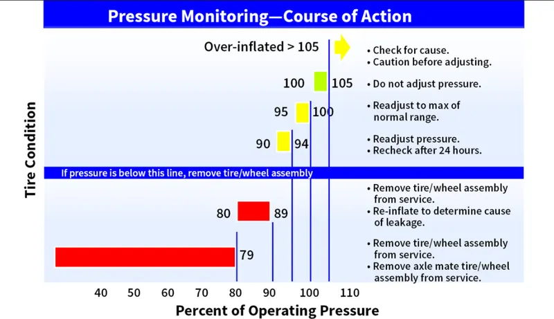
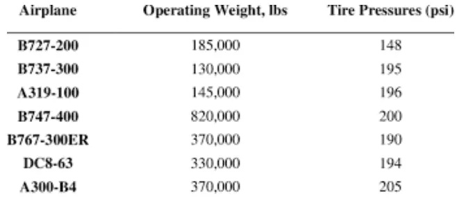
Aircraft tires generally operate at high pressures, up to 200 psi (14 bar; 1,400 kPa) for airliners, and even higher for business jets. The main landing gear on the Concorde was typically inflated to 232 psi (16.0 bar), whilst its tail bumper gear tires were as high as 294 psi (20.3 bar)
Braking
Aircraft brakes stop a moving aircraft by converting its kinetic energy to heat energy by means of friction between rotating and stationary discs located in brake assemblies in the wheels.
 A brake assembly on a Boeing 737NG main landing gear, visible after removal of one the wheels. Source: SKYbrary (Click image to enlarge)
Brakes provide this critical stopping function during landings to enable airplanes to stop within the length of the runway. They also stop aircraft during rejected takeoff events, in which an attempted takeoff is canceled as the airplane is rolling down the runway before it lifts off from the ground due to engine failure, tire blowout, other system failure or direction from air traffic control.
Aircraft brakes also prevent motion of the aircraft when it is parked, limit its speed during taxiing and can even help steer the aircraft on the ground by applying different levels of braking force to the left- and right-side brakes.
Aircraft brakes work in conjunction with other brake mechanisms such as thrust reversers, air brakes and spoilers. Thrust reversers are surfaces that are deployed into the path of the jet blast from the engines to redirect propulsive thrust in a direction that opposes the motion of the aircraft. Air brakes and spoilers are flight control surfaces that create additional aerodynamic drag when deployed into the path of air flowing around the aircraft.
How aircraft brakes work
The most common type of brake used on aircraft is the disc brake. Disc brakes function by exploiting friction between rotating and stationary discs inside the brake.
Upon receiving a command signal to brake — from the pilot depressing a foot pedal or from the autobrake system — actuators in the brake move a piston to squeeze the discs together, generating a frictional force that slows the rotation of the wheel. The friction between the discs generates heat as the aircraft’s kinetic energy is converted to heat energy. In this function, the brakes act as a heat sink, absorbing tremendous amounts of heat as the aircraft sheds kinetic energy. During RTO stops, the temperature of carbon disc brakes can exceed 1,800° C.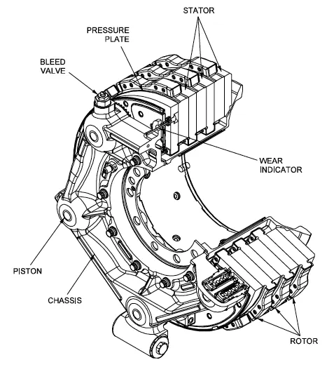 Gulfstream G450 main landing gear brake assembly. Source: G450 Maintenance Manual via Code 7700
The discs are mounted on a carrier assembly consisting of a torque tube, which resists and transmits brake torque to the landing gear structure. Sandwiched together between the carrier assembly housing and a backing plate, the discs are arranged in an alternating pattern of rotors and stators. Notch and groove geometry around the circumference of each rotor fits into corresponding geometry in the wheel, keying the rotors to the wheel so that they rotate with it. The stators are keyed to the torque tube and are thus held stationary since the torque tube is connected to the axle and landing gear structure.
Cylindrical spaces within the carrier assembly hold actuator pistons. Braking occurs as piston force squeezes the discs together.
During each application of the brakes, disc material is worn away by frictional forces. A wear indicator in the form of a pin that protrudes out of the carrier assembly indicates the thickness of the stack of discs. Over hundreds of brake applications, material wears away and discs become thinner, requiring replacement following periodic maintenance intervals.
Brake design
The primary design considerations for aircraft brakes include the number of discs, the diameter of the discs and the material of the discs.
A major design point around which aircraft brakes are designed is the worst-case scenario of rejected takeoff (RTO) at the maximum rolling speed V1, known as the decision speed. Above V1, a takeoff could not be safely aborted without serious risk of the airplane failing to stop before the end of the runway. In this situation, the brakes need to absorb more energy than any other scenario.
 An A380’s brakes exhibit a red-hot glow during a rejected take off (RTO) test on the runway at ISTRES AFB in the south of France. Source: Airbus (Click image to enlarge)
To illustrate how much energy this is, consider an Airbus A380 — the world’s biggest passenger airplane — performing an RTO at V1. The maximum take-off weight of an A380 is 575,000 kg (1,267,658 lb) and its maximum V1 is around 170 knots (about 195 mph or 87 m/s). A rough estimate for the maximum energy that the A380’s 16 brakes need to dissipate during RTO can be obtained by calculating the kinetic energy of the aircraft (neglecting the effects of thrust reversers, air brakes, tailwinds, headwinds and runway slope).
Since kinetic energy (KE) is a function of mass (m) and velocity (v) according to the equation:
KE = ½mv2
The kinetic energy of the A380 during RTO is calculated as follows:
KE = 0.5 * 575,000 kg * (87.4556 m/s)2 = 2.2 x 10⁹ J = 2.2 GJ
2.2 GJ (gigajoules) is about the amount of energy an average cloud-to-ground lightning strike dissipates. It is also enough energy to power an 8 W LED light bulb (with light output equivalent to a 60 W light bulb) continuously for 8 years and 10 months.
To generate the necessary frictional forces and to handle this much energy within the length of a runway, large commercial transport aircraft typically require multiple discs per brake assembly and brakes on most, if not all, of their wheels.
For example, an A380 has 22 wheels distributed on five landing gear legs to support its massive weight: two nose wheels on a leg beneath the nose of the aircraft, eight wing wheels split between two legs that fold out from under the fuselage to support the left and right wings, and 12 body wheels split between two inboard landing gear legs under the fuselage. Sixteen of these wheels have brakes (four aft body wheels and the nose wheels are not braked).
The A380 uses Honeywell’s Carbenix brakes. Each of the aircraft’s 16 brake assemblies has five rotors made of Carbenix 4000 carbon-carbon composite. The brake assemblies are located within wheels made of 2014-T6 aluminum alloy and attached to the axle and landing gear structure, which is comprised of 300 M high-strength alloy steel, titanium and aluminum components.
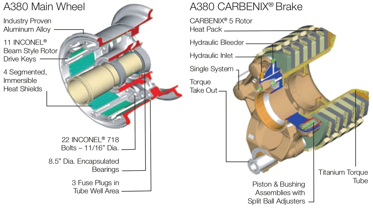 A380 main wheel and brake.
Brake materials
The most common aircraft brake disc material until around 1963 was steel. The introduction of beryllium as a disc material provided improved thermal properties at the cost of material handling difficulties due to the toxic nature of beryllium oxide.
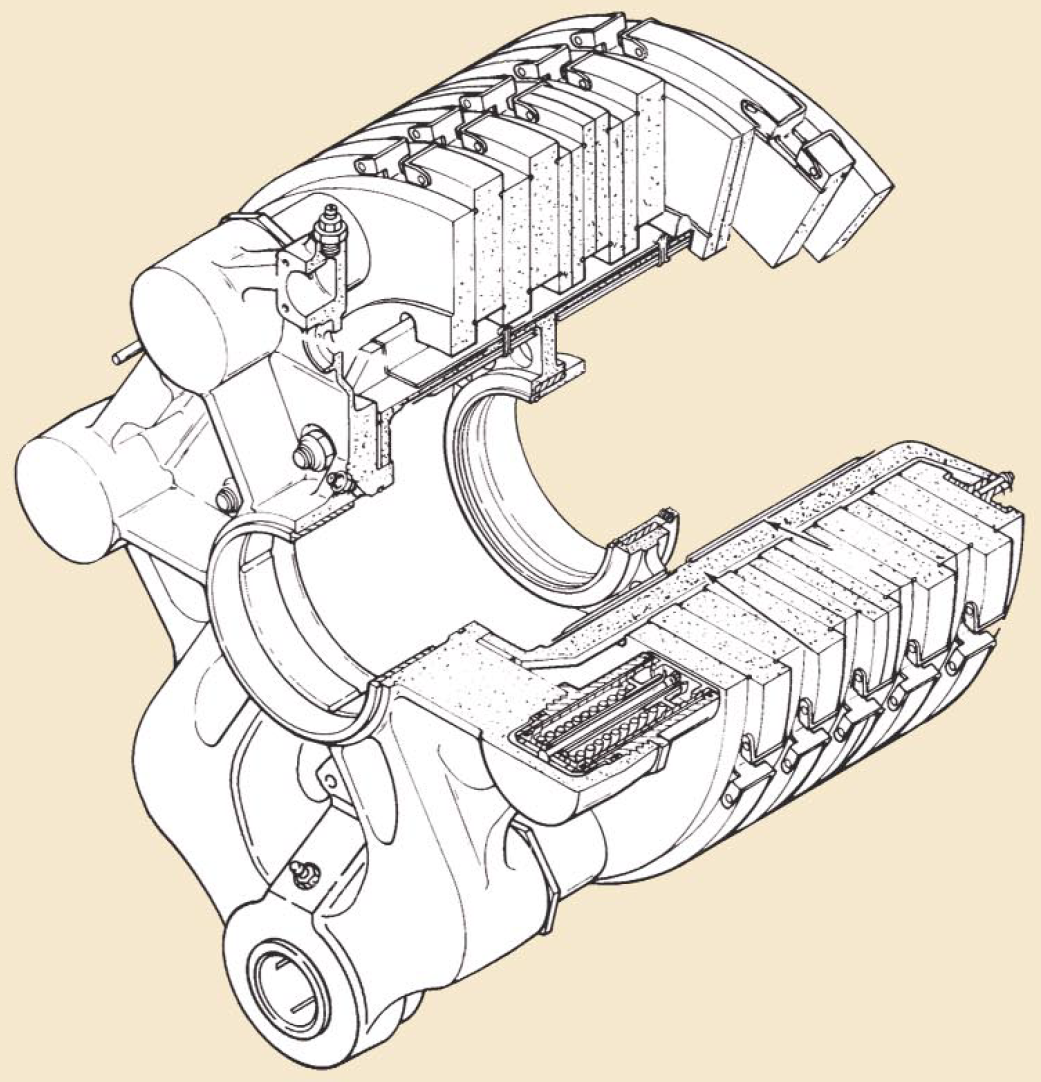 Boeing 767 carbon brake. Source: Honeywell Landing Systems via Boeing
Carbon brakes became widely available for commercial airplanes starting in the 1980s. Carbon brakes — made of, for example, carbon fibers in a graphite matrix — are lighter, more durable, less thermally sensitive and have higher energy absorption and faster cooling rates compared to steel brakes.
Compared to steel, carbon’s higher specific heat — the amount of heat that a unit mass of carbon absorbs to raise its temperature by one unit — enables reduced brake weight. Carbon’s higher thermal conductivity allows faster heat transfer and uniform heat distribution through the disc. Carbon also has lower thermal expansion, higher thermal shock resistance and a higher temperature limit than steel. The specific strength of carbon is relatively constant over a very wide range of temperatures, unlike steel and beryllium, which both exhibit steep declines in specific strength at high temperatures, dropping below carbon around 650° C (1,200° F).
Safran Landing Systems claims its Sepcarb III oxidation-resistant carbon brakes used on Boeing 787s are four times lighter, have three times higher endurance and have two to three times higher absorption capacity than steel brakes. UTC Aerospace Systems said its Duracarb carbon disk technology results in a weight-savings of 700 lbs (318 kg) per airplane for Boeing 737NGs compared to steel brakes.
Other brake materials are available as well, such as Honeywell’s Cerametalix, a sintered combination of powdered metals and ceramics.
Brake actuator type
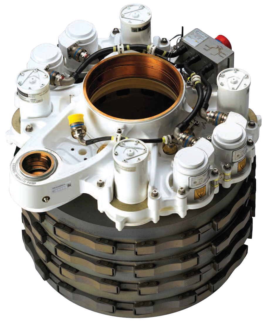 Boeing 787 electric brake. Source: Safran Landing Systems (Click image to enlarge)Brake actuators perform the critical task of squeezing discs together to generate the frictional forces that convert the aircraft’s kinetic energy of motion into heat to stop the aircraft. Most brake actuators on commercial aircraft are hydraulic, although electrically powered electromechanical actuators have entered service as well; the brakes on both the Airbus A220 (formerly known as the Bombardier C-series) and the 787 are electromechanically actuated.
Hydraulic brakes are powered by the aircraft’s hydraulic system. A servo valve modulates the flow of hydraulic fluid to the hydraulic actuator to control the amount of braking force — the force with which the hydraulic cylinder presses the discs together.
Electric brakes are powered by the aircraft’s electric system. Electricity is converted to mechanical power in the brake’s electromechanical actuators. In these actuators, an electric motor drives gears to turn a ball screw and nut to apply force to press the brake discs together.
Redundancy is a necessary attribute built into aircraft braking systems due to the critical safety function that brakes provide. For example, the A380’s hydraulic brake system is powered by multiple separate 5,000 psi hydraulic systems. The set of brakes on the wing wheels and the set of brakes on the body wheels are attached to two separate hydraulic systems. The brake system is also supplied by a backup hydraulic system called the local electrohydraulic generation supply (LEHGS), which provides an alternate source of hydraulic power in the event of primary hydraulic system failure. The LEHGS generates hydraulic pressure with an electric motor-driven pump supplied by the aircraft’s electrical system.
The design for the 787’s Electric brakes also features redundancy. With four independent electromechanical actuators per wheel, operation of the 787 is permissible with 100% braking function available even if one of the electric brake actuators (EBAs) fails. The modular nature of the EBAs enables easy, in-situ maintenance during which a failed EBA can be quickly swapped out for a new one.
Brake cooling
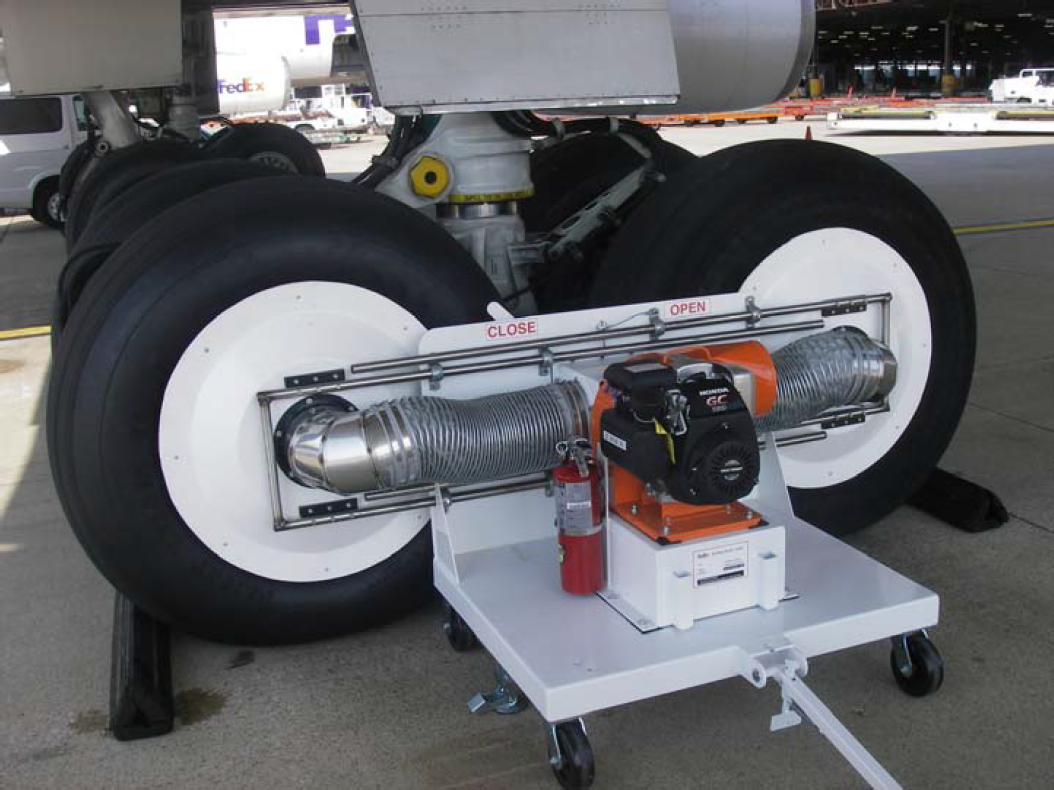 The GS100 aircraft brake cooler has a gas or diesel engine-powered fan that provides suction cooling for fast turnaround times. Source: Ground Support Specialists, LLC. (Click image to enlarge)The large amount of heat generated during aircraft braking is dissipated by means of passive or active cooling. Passive cooling occurs due to natural conduction of heat through the disc material and to surrounding components, radiation of heat off the brake and wheel assembly, and convection as air flows past and through the brake assembly. Active cooling is achieved by using fans that force air through the brakes. Fansare either built into the wheel or part of the external ground support equipment that is positioned against the wheel and removed once sufficient temperature drop has occurred.
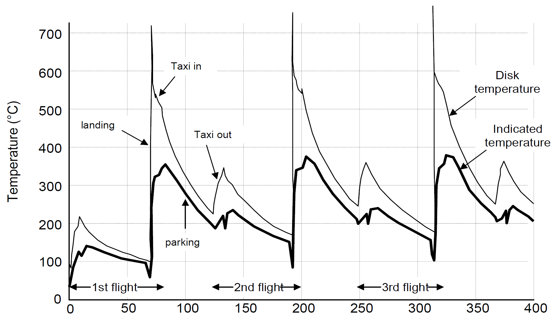 Example of brake temperature over time after three takeoff and landing cycles. Toward the end of a busy day full of short flights, it may be necessary to mandate a cooling period for hot brakes, during which the aircraft remains on the ground, to allow the brakes to cool so that they will not exceed the acceptable operating temperature range during RTO or landing. Source: Airbus (Click image to enlarge)
Autobrakes and skid control
Modern commercial aircraft are equipped with an autobrake system that controls the deceleration of the aircraft by automatically optimizing the application of brake force independent of pilot operation of the brake pedals to minimize stopping distance, reduce pilot workload and smooth braking action.
Another common feature of aircraft brake systems is a skid control function. Similar to anti-lock brakes on an automobile, skid control systems prevent wheel lockup. They minimize stopping distance and prevent the negative effects of skidding on tires such as unnecessary tire wear and blowout. Skid control is accomplished by applying an optimal brake force that maximizes the coefficient of friction and remains just below the amount of force that would cause skidding. In one implementation, the proper force is arrived at by continuously sensing wheel speed and comparing it to a calculated aircraft velocity. The difference between the two values represents wheel slip and brake force is reduced if it rises above a specified value.
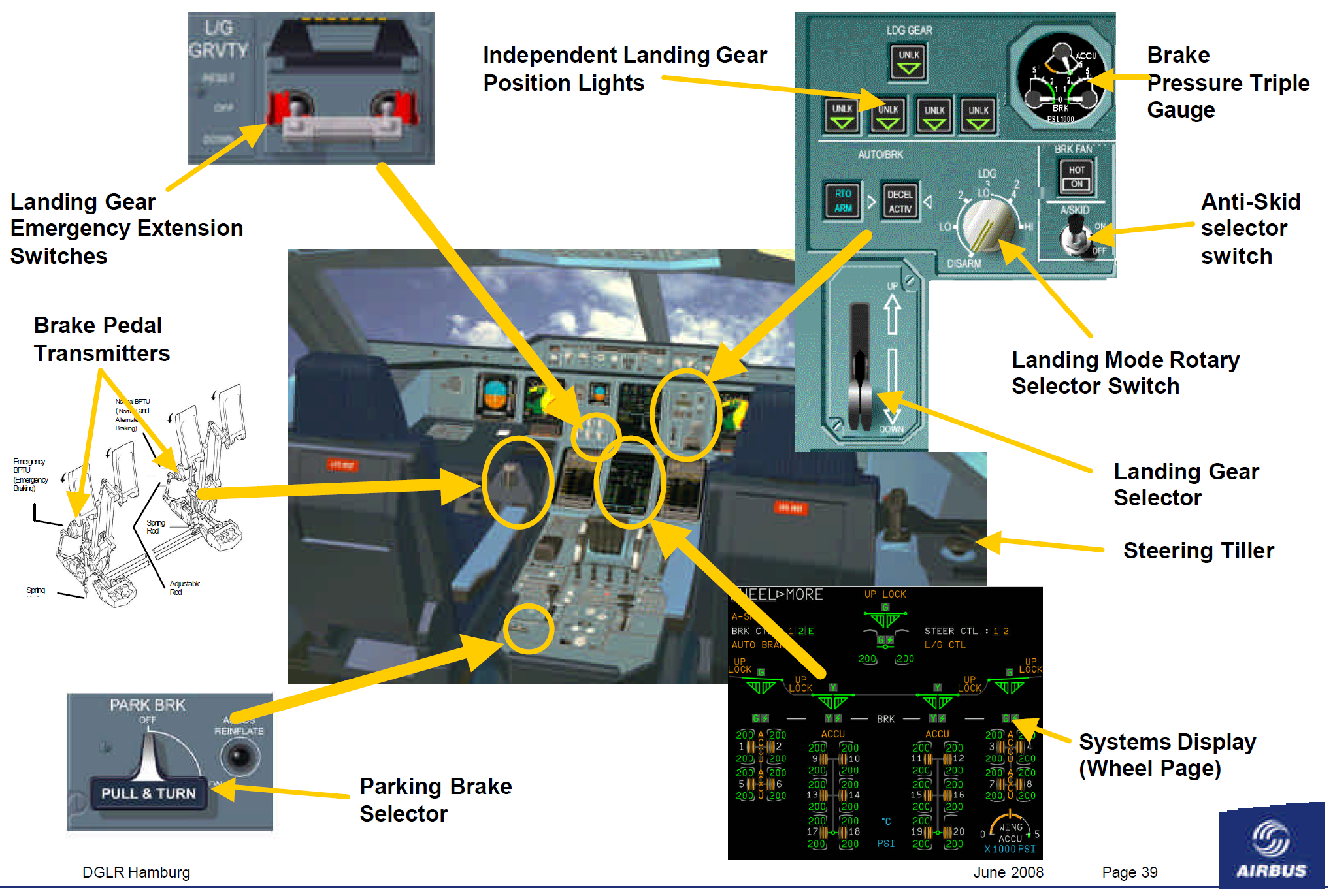
Cockpit controls, display and indicators for the A380’s landing gear and brakes.
Part B:
6. A. With necessary assumptions, calculate the force and power required to push / pull an aircraft by a towing vehicle.
Assume force & power of towing the AIRbus A350aircraft.
Air density=1.25kg/m^3,
drag coeffeicient of towing vehicle(cd1)=0.5
drag coeffeicient of aircraft (cd2)=0.0265
total drag coeffeicient(cd)=0.5265
total frontal area(a)=25m^2
rolling resistance on dry concrete=0.05
wieght of airbus A380=284500kg
weight of the towing vehicle=15500kg
total weight=300000kg
max.towing speed=10kmph=2.78m/s
acceleration time=25s
acceleration=v/t=0.1112m/s^2
total tractive force for towing aircraft when acceleration is 0.1112m/s^2 & reaching max.speedrr
force=Fad+Frr+Fla+Fhc
hill climbing force is zero at the airport so Fhc=0
force=(0.5*ρ*A*Cd*V^2)+(μrr*m*g)+(m*a)
force=(0.5*1.2*25*0.5265*2.78^2)+(0.05*300000*9.81)+(300000*0.1112)
force=63.578+147150+33360
force=180.573KN
total tractive force for towing aircraft,when towing vehicles run at max speed10kmph after acceleration.now the acceleration force is zero & hill climbing force also zero
force=Fad+Frr
force=(0.5*ρ*A*Cd*V^2)+(μrr*m*g)
force=(0.5*1.2*25*0.5265*2.78^2)+(0.05*300000*9.81)
force=63.578+147150
force=147.213KN
power=force*velocity
total tractive power for towing the aircraft when the acceleration is0.112m/s^2 & reaching max.speed
peak power=180.573*2.78
=501.99KW
total tractive power for towing the aircraft when towing th vehicle srun at max.speed 10kmph after acceleration
normal power=147.213*2.78
=409.252KW
force required by towing vehicles to move the aircraft
force=147.213KN
Peakforce=187.573KN
B. Develop the model for the calculated force and power using Simulink
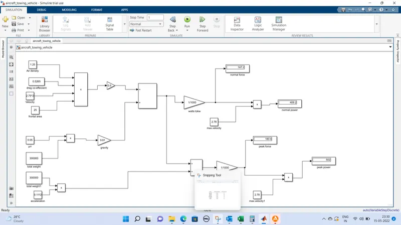
normal power=409.252KW
peak power=521.453KW
7. A. Design an electric powertrain with type of motor, it’s power rating, and energy requirement to fulfill aircraft towing application in Simulink. Estimate the duty cycle range to control the aircraft speed from zero to highest. Make all required assumptions. Prepare a table of assumed parameters. Draw a block diagram of powertrain.
Since DC7 block not available

consideration towing vehicle & aircraft
mass of towing vehicle=5000kg
mass of boeing 757=127006kg
radius of towing machine=0.33m
accleration due to gravity=9.81m/s^2
rolling resistance coeffecient=0.01(asphalt road conditons for heavy trucks)
frontal area of aircraft =450m^2
density of air(according to international std)=1.225k/m^3
velocity with which vehicle loaded=6kmphor=1.611m/s
Cd drag coeeffiecient=0.02
rolling resistance force for aircraft to be towedFrr=16.677KN
aerodynamic force=17.52N
power required to move the aircraft by tow vehicle=26.89KW
toque required to move the aircraft by towing vehicle=5509.35Nm
BLOCK DIAGRAM OF EV
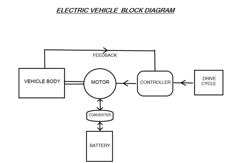
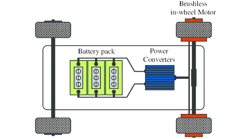
so from the above results of power required is 26.89/kw& now particular rated powered motor will be required to assist the towing vehicle to mone the aircraft,here we are using the BLDC motor as it gives a good constant torque work effeiciency & also get cooled by conductions &requires no additional cooling mechanism
Motor design
so let us assume a 45KW DC brushless motor,nominal power=45kw,nominal voltage=230V
nomial current=220A winding configurations:delta,construction : 48slots, 40 magnets,lamination :M330
cooling: glycat, weight 17kg, cooper weight; 2.7kg
Windings: can be delta or star,delta coonections will give you higher power per copper amount higher rpm higher current lower phase volts.star will give you lower RPM,higher torque higher volts lower the current
from the ABOVE MOTOR design
rated voltage=230V
rated current=200A
rated power=V*I=230*200
46KW
so from the above choosen motor the output power will be 45kw & power required by towng vehicles is26.89kw
Total power reated can be supplied=45kw
Duty cycly efficiency=output power/input power
D=26.89/45
=59.75=0.6
total duty cycle percentage =60%
total energy supplied to move the towing vehicle =power input to TOW*time taken to move the aircraft by towing vehiles
E=p*time
p=26.89kw
time taken to move the aircraft by towing vehicle =5min=0.25hours
E=26.89*0.5=6.7225Kwh
Energy required to move the aircraft by towing the vehcile for 15min with 6kmph velocity=6.7225Kwh
Design the parameters in excel sheet.