Project-1: Powertrain for aircraft in runways
LIVE SESSION BATCH MEMBER
Part A:
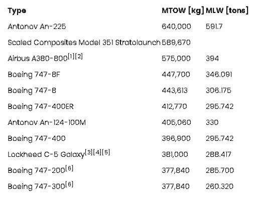
1. Search and list out the total weight of various types of aircrafts.
2. Is there any difference between ground speed and air speed?
3. Why is it not recommended to use aircraft engine power to move it on the ground at Airport?
4. How an aircraft is pushed to runway when its ready to take off?
5. Learn about take off power, tyre design, rolling resistance, tyre pressure, brake forces when landing.
ANSWER:-
1.Search and list out the total weight of various types of aircrafts.
- The aircraft gross weight is the total weight at during in flight and at ground position.
- It weight decreases during flight because of fuel consumption.
- During flight the total weight i equal to the enrute weight or flight weight
Below are the some different types of aircrafts of total weight:-
2.Is there any difference between ground speed and air speed?
Ground Speed:-
- Ground speed means the speed of an aircraft with respect to the ground reference.
- The ground speed includes the wind speed and air speed.
- The ground speed can determine how fast the aircraft can reach its destination.
Air Speed:-
- It is the reference of wind speed.
- It is the speed required for aircraft to lift.
- Airspeed = ground speed[ stand still position] , and air speed will be lesser than ground speed when the aircraft moving along the wind direction
- There are three types of air speed, indicator airspeed, True air speed, Calibrated air speed.
3. Why is it not recommended to use aircraft engine power to move it on the ground at Airport?
- more noise is occured while starting the engine.
- fuel consumption will be happen again it is waste of energy.
- The use of engine thrust is prohibited near terminals due to possibility of air blast.
- smoke and dust will be formed and it can be sucked into engine and it may leads to engine failure.
- thus towing vehicles are used for this purpose .
4. How an aircraft is pushed to runway when its ready to take off?
- By using towing vehicle the aircraft can be moved from parkinfg area to runway.
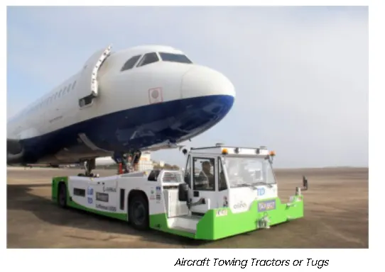
- Due to airport restrictions using engine aircraft also prohibited and for this operation towing vehicle used to pull the vehicle forward or reverse.
- By pass pin is disconnected and the ground handler will inform the pilot that aircraft can move on its ow.
5. Learn about take off power, tyre design, rolling resistance, tyre pressure, brake forces when landing.
Take off power:-
- The take off power depends upon the kinetic energy and potential energy where E=0.5 MV^2+(MGH).
- where m= mass of aircraft,
- G= gravitational constant
- H= height of the aircraft.
Tyre design:-
- while considering tyre design it should withstand the heat resistance.
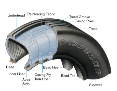
- The design includes various testing for efficiency or else the failure percentage will not be controlled
Rolling Resistance:-
- we know the rolling resistance Frr= μrr m.g
- Where μrr= coefficient of rr ,m=mass of vehicle, g = gravitational constant )
- rolling resistance can be experienced while take off and while landing.
Brake force when landing:-
- There are various braking involves in say , engine braking , hydraulic braking & mechanical braking.
- In engine braking it stops the forward acceleration of the aircraft.
- In hydraulic braking it is applied while it touches the a ground level.
- Whereas in mechanical braking it helps to deaccelerate the aircraft with the help of its wings.
Part B:
6. A. With necessary assumptions, calculate the force and power required to push / pull an aircraft by a towing vehicle.
ANSWER:-
The given data is taken from towing truck TMX-150-9 & Aircraft airbus A319
GIVEN DATA:-
- Mass of the truck = 8300 Kg
- Mass of the aircraft =75.500 Kg
- Length of the aircraft = 33.84m
- Velocity of the truck = 25kmph
- Height of the aircraft =11.76 rn
- Air density (p)=1.225 Kg/m^3
- Drag coefficient (Cd) =0.75
- Rolling resistance coefficient (μrr) = 0.013
- Gravitational constant (g) = 9.8 Nm
Calculation of rolling resistance (Frr):-
- Frr= μrr m.g
- mass (m) = mass of truck + mass of aircraft = 8300+75500
- M= 83800 kg
- Buy substituting ,
- Frr = 0.013*82800*9.8
- Frr= 10676.12 NM
Calculation For aerodynamic drag (Fad):-
- Fad= 0.5*p*Cd*A*V^2
- Velocity of the truck (m/sec) = 25 /3.6 = 6.95 m/s,
- Area = length of the aircraft * Height of the aircraft
- Area= 392.544 m^2
- Fad= 0.5*1.225*0.75*392.544*6.95^2
- Fad = 8816 N
Total Force required to push / pull an aircraft by a towing vehicle Is:-
In Newton:-
- Ftotal = Frr+Fad = 10676.12 + 8816
- Ftotal= 19492.8 N
In power:-
- Power = Ftotal* velocity
- Power = 18258.8 * 6.95
- Power = 135.363 Kw
B. Develop the model for the calculated force and power using Simulink.
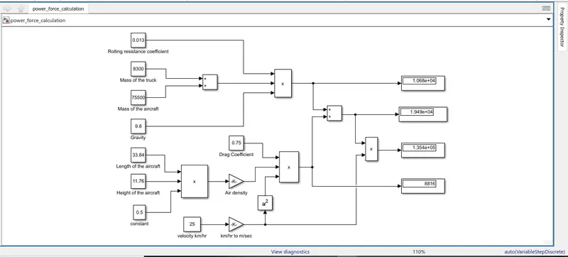
- we used the constant blocks for the datas, and by using gain blocks we usually convert the km/hr to m/sec.
- we use the product blocks for multiplying the frr and fad.
- we used the display block for the visualize the output.
7. A. Design an electric powertrain with type of motor, it’s power rating, and energy requirement to fulfill aircraft towing application in Simulink. Estimate the duty cycle range to control the aircraft speed from zero to highest. Make all required assumptions. Prepare a table of assumed parameters. Draw a block diagram of powertrain.
(Hint :DC7 Block)
ANSWER:-
AIM:-
- To study about the aircraft towing process in the airports
- To estimate the load, speed and other operating conditions of the towing tractor in the airport
- To design the towing tractor with electric drivetroin which should be able to fulfil the above requirements
Objective of The Project:
- In Airport the Aircrofts will be there and they will either Take off to attain the flight or they will land in the airport from their flight
- Usually after when the aircraft is loaded with passengers and luggoges, they ore ready to take oft and while doing that the oircraft has to reach the straight runway rhorder to attain required speed for it to fly ih the oir.
- In this process -from the flight boarding area (i.e) the terminal that to reach the run way and it is called as taxiway.
- For doing this, the flights propeller power is not used. Instead a aircraft towing tractor is used to push or pull the aircraft to the runway.
- This project is to design the aircraft towing tractor with an electric drivetroin to meet out the needs of towing on aircraft lh order to design this towing tractor with on electric drivetrain first we need to study oh certain areas.
Required:-
- MATLAB
- POWER TRAIN BLOCK SET
Designing Procedures:
- The correct way to design any vehicle D by reverse engineering. This con be done with the below f our steps,
- First the vehicle's area of usage has to be studied that includes on what conditions,. need our vehicle to perform and On what speed, load, and other operating conditions,
- How much power we are in need to operate our vehicle in the desierecl conditions
- What all necessary things need to be calculated and analysed.
- Then after calculating we need to go for proper selection of motor and power train.
Block Diagram:-
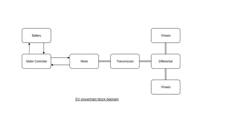
- The below fig shows the electric power train block diagram:-
Calculations and assumed data:-
- we have calculated the power requird for towing of a aircraft.
- we are going to design a power train for the same question no.6
- Towing truck TMX-150-9 & Aircraft airbus A319 & tyre specification is 315/70 R15.
Data For Designing :-
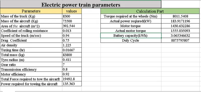
- Force required for towing vehicle = 19492.8 N
- Power required for towing the aircraft = 135.363KW
- Tyre radius for the towing truck=0.411m
- Gear ratio=7
- Transmission Efficiency (ηt) = 80%
- Motor Efficieny (ηm) = 92%
Torque required for the wheels (Tw):-
- Tw= Total force * Tyre radius = 19492*0.411
- Tw= 8011.212 Nm
Actual power (Pac):-
- Pac= (Power required)/(ηt*ηm) = 135.363 K/(0.8*0.92)
- Pac = 183.917KW
- It is the motor power rating should be around 190 Kw.
To calculate Motor torque(Tm):-
- Tm= (Tw)/(Gear ratio*ηt) = 8011.212/(0.8*0.92)
- Tm= 1.430 kNm
Actual motor torque (Tmac):-
- Tmac = (Tm)/(ηm) = 5.6/0.92
- Tmac=1.555 kNm
To Calculate battery Capacity:-
- The towing vehicle takes 15 mins for taxing (which runs on yellow line)
- converting 15 mins to hrs we get 0.016667hrs
- Battery capacity = Pac*hours = 0.016667 * 183.917
- Battery capacity = 3.067KWh
- The battery MUst Deliver the power output of 3.067 Kwh
- If we use the 210 KW battery We can run the towing vehicle easily.
Duty Cycle Calculation:-
- Duty Cycle = (Power required (Pac))/(Power rated (battery capacity)) = 183.917/210
- Duty cycle=(0-0.875)
- To run the towing vehicle for 15 mins with speed of 7 m/sec the duty cycle varies between (0 to 0.875)
- At the max speed of 7 m/sec the towing vehicle reaches the 0.875 meters.
DC-7 Four Quadrant Chopper :-
- The 200 HP DC motor is separately excited with a constant 150 V DC field voltage source. The armature voltage is provided by an IGBT converter controlled by two PI regulators.
- The converter is fed by a 515 V DC bus obtained by rectification of a 380 V AC 50 Hz voltage source. In order to limit the DC bus voltage during dynamic braking mode, a braking chopper has been added between the diode rectifier and the DC7 block.
- The first regulator is a speed regulator, followed by a current regulator. The speed regulator outputs the armature current reference (in p.u.) used by the current controller in order to obtain the electromagnetic torque needed to reach the desired speed.
- The speed reference change rate follows acceleration and deceleration ramps in order to avoid sudden reference changes that could cause armature over-current and destabilize the system.
- The current regulator controls the armature current by computing the appropriate duty ratios of the 5 kHz pulses of the four IGBT devices (Pulse Width Modulation).
- For proper system behaviour, the instantaneous pulse values of IGBT devices 1 and 4 are opposite to those of IGBT devices 2 and 3. This generates the average armature voltage needed to obtain the desired armature current.
- In order to limit the amplitude of the current oscillations, a smoothing inductance is placed in series with the armature circuit.
SIMULINK MODEL:-
(I DONT HAVE POWER TRAIN BLOCK SET AS I AM HAVING MATLAB TRIAL VERSION)
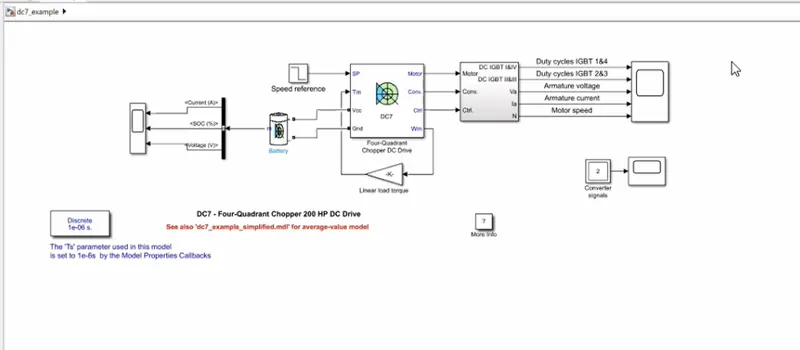
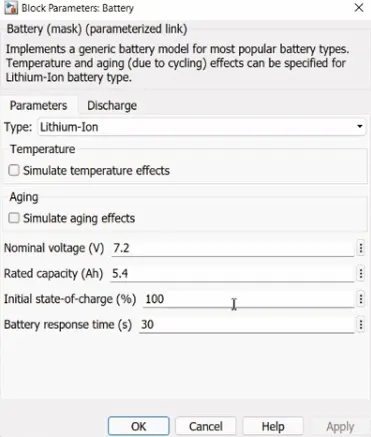
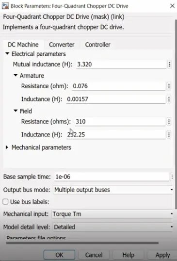
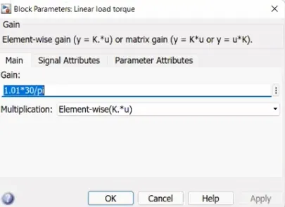
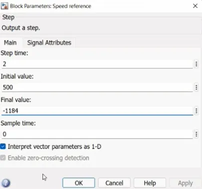
- As mentioned above we have set the parameters into the simulink model ,
- we have speed controller and current controller and we have seperately excited motor .
- There is a sperate excitation with voltage source(field excitation).
- In the chopper we have igbt thyristors connected like mapped model.
- Discrete model is used for this model due to battery we used by using in powergui block.
- We have derived the equations for power calculation and distance travelled for particular time and speed.
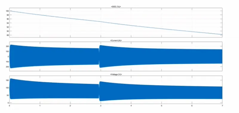
- From above plot we can understand the battery ,SOC, voltage , current.
- At the starting tme we can see th sudden rush of staring current,as battery is set to 80 volt.
- here battery percentage is reduced to 88 % in the short duration of time due to its heavy usage
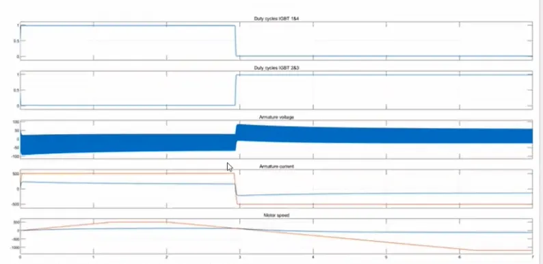
- From the above plot we can see the duty cycle of the power converter.
- The duty cycle is setted as 87% for the battery usage of battery power.
- By using the DC7 converter the motor is tested in both forward and reverse direction.
B. Also, Design the parameters in excel sheet.