Project-1: Powertrain for aircraft in runways
- Search and list out the total weight of various types of aircrafts.
The list out the total weight there are.
- Manufacturer's empty weight
- Zero-fuel weight
- Operating Empty weight
- Payload
- Maximum take-off weight (MTOW)
- Maximum landing weight (MLW)
- Maximum ramp weight (MRW)
- Aircraft gross weight
- Manufacturer's empty weight
In aviation, manufacturer's empty weight (MEW) (also known as manufacturer's weight empty (MWE)) is the weight of the aircraft "as built" and includes the weight of the structure, power plant, furnishings, installations, systems, and other equipment that are considered an integral part of an aircraft before additional operator items are added for operation.
Basic aircraft empty weight is essentially the same and excludes any baggage, passengers, or usable fuel. Some manufacturers define this empty weight as including optional equipment, i.e., GPS units, cargo baskets, or spotlights.
- Zero-fuel weight
The zero-fuel weight (ZFW) of an aircraft is the total weight of the airplane and all its contents, minus the total weight of the usable fuel on board. Unusable fuel is included in ZFW.
For example, if an aircraft is flying at a weight of 5,000 kg and the weight of fuel on board is 500 kg, the ZFW is 4,500 kg. Sometime later, after 100 kg of fuel has been used, the total weight of the airplane is 4,900 kg, the weight of fuel is 400 kg, and the ZFW is unchanged at 4,500 kg.
As a flight progresses and fuel is consumed, the total weight of the airplane reduces, but the ZFW remains constant (unless some part of the load, such as parachutists or stores, is jettisoned in flight)
- Operating Empty weight
Empty weight (EW) is the sum of the ‘as built’ manufacturer's empty weight (MEW), plus any standard items (SI) plus any operator items (OI), EW = MEW + SI + OI. The EW is calculated for each aircraft series and each unique configuration of an aircraft and is confirmed by periodically weighing it. The "Operating empty weight" (OEW) is the sum of the empty weight and the crew plus their baggage.
Standard items include all structural modification or configuration orders that may have altered the MEW, including all fluids necessary for operation such as engine oil, engine coolant, water, hydraulic fluid and unusable fuel. Operator items include fixed, optional equipment added by the operator for service reasons.
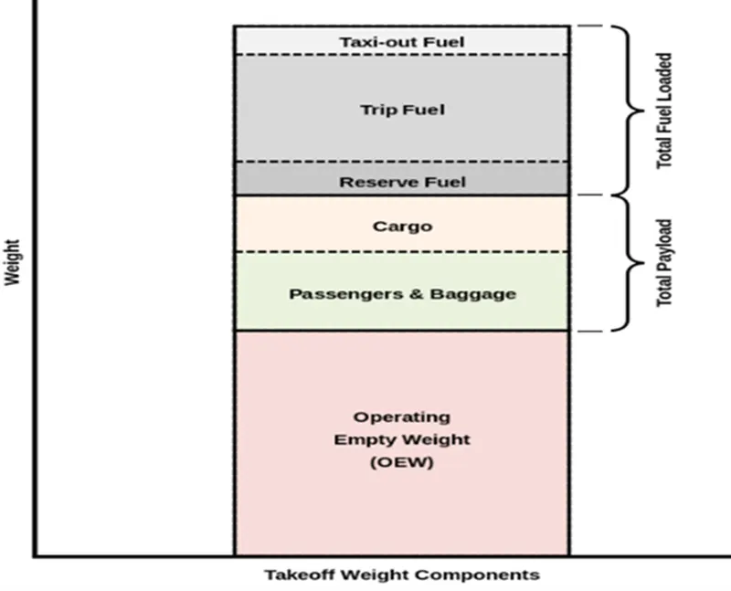
The weight added to the aircraft above its OEW for a given flight is variable and includes fuel for the flight and the cargo. Cargo depends upon the type of aircraft; i.e., passengers plus baggage for a transport or commuter airplane, materiel for a cargo airplane, stores for fighters/bombers and service loads such as meals and beverages. Fuel and cargo weights may alter the centre of gravity and flight performance, and require careful calculation before each flight.
- Payload
Payload is the object or the entity which is being carried by an aircraft or launch vehicle. Sometimes payload also refers to the carrying capacity of an aircraft or launch vehicle, usually measured in terms of weight. Depending on the nature of the flight or mission, the payload of a vehicle may include cargo, passengers, flight crew, munitions, scientific instruments or experiments, or other equipment. Extra fuel, when optionally carried, is also considered part of the payload.
- Maximum take-off weight(MTOW)
The maximum take-off weight (MTOW) or maximum gross take-off weight (MGTOW) or maximum take-off mass (MTOM) of an aircraft is the maximum weight at which the pilot is allowed to attempt to take off, due to structural or other limits. The analogous term for rockets is gross lift-off mass, or GLOW. MTOW is usually specified in units of kilograms or pounds.
MTOW is the heaviest weight at which the aircraft has been shown to meet all the airworthiness requirements applicable to it. MTOW of an aircraft is fixed and does not vary with altitude, air temperature, or the length of the runway to be used for take-off or landing.
Maximum permissible take-off weight or "regulated take-off weight", varies according to flap setting, altitude, air temperature, length of runway and other factors. It is different from one take-off to the next, but can never be higher than the MTOW.
- Maximum landing weight (MLW)
The maximum landing weight (MLW) is the maximum
aircraft gross weight due to design or operational limitations at which an aircraft is permitted to land. The MLW is set in order to ensure safe landings; if an aircraft weighs too heavy during touchdown, it may suffer structural damage or even break apart upon landing. Aircraft also have a maximum take-off weight, which is almost always higher than the maximum landing weight, so that an aircraft can weigh less upon landing due to burning fuel during the flight.
- Maximum ramp weight (MRW)
The maximum ramp weight (MRW) (also known as the maximum taxi weight (MTW)) is the maximum weight authorised for manoeuvring (taxiing or towing) an aircraft on the ground as limited by aircraft strength and airworthiness requirements. It includes the weight of taxi and run-up fuel for the engines and the auxiliary power unit (APU).
It is greater than the maximum take-off weight due to the fuel that will be burned during the taxi and run-up operations.
The difference between the maximum taxi/ramp weight and the maximum take-off weight (maximum taxi fuel allowance) depends on the size of the aircraft, the number of engines, APU operation, and engines/APU fuel consumption, and is typically assumed for 10 to 15 minutes allowance of taxi and run-up operations
- Aircraft gross weight
The aircraft gross weight (also known as the all-up weight and abbreviated AUW) is the total aircraft weight at any moment during the flight or ground operation.
An aircraft's gross weight will decrease during a flight due to fuel and oil consumption. An aircraft's gross weight may also vary during a flight due to payload dropping or in-flight refuelling.
At the moment of releasing its brakes, the gross weight of an aircraft is equal to its take-off weight. During flight, an aircraft's gross weight is referred to as the en-route weight or in-flight weight.
Maximum design taxi weight (MDTW)
The maximum design taxi weight (also known as the maximum design ramp weight (MDRW)) is the maximum weight certificated for aircraft manoeuvring on the ground (taxiing or towing) as limited by aircraft strength and airworthiness requirements.
Maximum design take-off weight (MDTOW)
Is the maximum certificated design weight when the brakes are released for take-off and is the greatest weight for which compliance with the relevant structural and engineering requirements has been demonstrated by the manufacturer.
Maximum design landing weight (MDLW)
The maximum certificated design weight at which the aircraft meets the appropriate landing certification requirements. It generally depends on the landing gear strength or the landing impact loads on certain parts of the wing structure.
The MDLW must not exceed the MDTOW.
The maximum landing weight is typically designed for 10 feet per second (600 feet per minute) sink rate at touch down with no structural damage.
Maximum design zero-fuel weight (MDZFW)
The maximum certificated design weight of the aircraft less all usable fuel and other specified usable agents (engine injection fluid, and other consumable propulsion agents). It is the maximum weight permitted before usable fuel and other specified usable fluids are loaded in specified sections of the airplane. The MDZFW is limited by strength and airworthiness requirements. At this weight, the subsequent addition of fuel will not result in the aircraft design strength being exceeded. The weight difference between the MDTOW and the MDZFW may be utilised only for the addition of fuel.
Minimum flight weight (MFW)
Minimum certificated weight for flight as limited by aircraft strength and airworthiness requirements.
various types of aircrafts
MTOW = Maximum take-off weight, MLW = Maximum landing weight, TOR = Take-off run (SL, ISA+15°, MTOW), LR = Landing run (SL, ISA+15°, MLW)
|
Type |
MTOW [kg] |
MLW [tonnes] |
TOR [m] |
LR [m] |
||
|
640,000 |
591.7 |
3500 |
Heavy |
Super |
||
|
589,670 |
3660 |
Heavy |
Super |
|||
|
575,000 |
394 |
3100 |
1930 |
Heavy |
Super |
|
|
447,700 |
346.091 |
3100 |
1800 |
Heavy |
Heavy |
|
|
443,613 |
306.175 |
3100 |
Heavy |
Heavy |
||
|
412,770 |
295.742 |
3090 |
Heavy |
Heavy |
||
|
Antonov An-124-100M |
405,060 |
330 |
2520 |
900 |
Heavy |
Heavy |
|
396,900 |
295.742 |
3018 |
2179 |
Heavy |
Heavy |
|
|
381,000 |
288.417 |
2530 |
1494 |
Heavy |
Heavy |
|
|
377,840 |
285.700 |
3338 |
2109 |
Heavy |
Heavy |
|
|
377,840 |
260.320 |
3222 |
1905 |
Heavy |
Heavy |
|
|
371,950 |
240 |
3050 |
2010 |
Heavy |
Heavy |
|
|
367,400 |
256 |
3100 |
2100 |
Heavy |
Heavy |
|
|
347,800 |
260.816 |
2830 |
Heavy |
Heavy |
||
|
351,800 |
251.29 |
3100 |
Heavy |
Heavy |
||
|
347,450 |
223.168 |
3000 |
Heavy |
Heavy |
||
|
340,200 |
265.300 |
Heavy |
Heavy |
|||
|
308,000 |
233.5 |
Heavy |
Heavy |
|||
|
299,370 |
237.683 |
3380 |
Heavy |
Heavy |
||
|
297,550 |
213.00 |
3380 |
1550 |
Heavy |
Heavy |
|
|
276,700 |
190 |
3000 |
1926 |
Heavy |
Heavy |
|
|
273,300 |
185 |
2990 |
1890 |
Heavy |
Heavy |
|
|
270,000 |
175 |
2670 |
1860 |
Heavy |
Heavy |
|
|
270,000 |
195.04 |
3115 |
2118 |
Heavy |
Heavy |
|
|
256,280 |
183 |
2990 |
1890 |
Heavy |
Heavy |
|
|
254,000 |
192.777 |
2900 |
Heavy |
Heavy |
||
|
254,000 |
201.849 |
Heavy |
Heavy |
|||
|
253,500 |
181 |
2990 |
Heavy |
Heavy |
||
|
251,000 |
191 |
3100 |
Heavy |
Heavy |
||
|
250,000 |
175 |
2600 |
1980 |
Heavy |
Heavy |
|
|
242,000 |
185 |
2500 |
1750 |
Heavy |
Heavy |
|
|
242,000 |
180 |
2220 |
1750 |
Heavy |
Heavy |
|
|
231,300 |
166.92 |
2636 |
Heavy |
Heavy |
||
|
228,000 |
172.365 |
3300 |
1695 |
Heavy |
Heavy |
|
|
211,400 |
Heavy |
Heavy |
||||
|
208,000 |
175 |
Heavy |
Heavy |
|||
|
204,000 |
158.758 |
3414 |
Heavy |
Heavy |
||
|
192,000 |
140 |
2385 |
1555 |
Heavy |
Heavy |
|
|
187,000 |
136.08 |
2713 |
1676 |
Heavy |
Heavy |
|
|
185,000 |
111.1 |
3440 |
2220 |
Heavy |
Heavy |
|
|
163,000 |
138 |
2324 |
1536 |
Heavy |
Heavy |
|
|
159,000 |
136.078 |
2713 |
1676 |
Heavy |
Heavy |
|
|
157,000 |
124 |
2290 |
1490 |
Heavy |
Heavy |
|
|
152,000 |
151.9 |
Heavy |
Heavy |
|||
|
151,000 |
97.5 |
Heavy |
Heavy |
|||
|
151,000 |
112.1 |
Heavy |
Heavy |
|||
|
147,000 |
Heavy |
Heavy |
||||
|
142,000 |
123 |
1860 |
1480 |
Heavy |
Heavy |
|
|
141,000 |
122 |
980 |
770 |
Heavy |
Heavy |
|
|
140,000 |
Heavy |
Heavy |
||||
|
125,000 |
Medium |
Large |
||||
|
124,000 |
101.6 |
2550 |
1750 |
Medium |
Large |
|
|
117,000 |
86.3 |
Medium |
Large |
|||
|
116,000 |
89.9 |
2347 |
1555 |
Medium |
Large |
|
|
106,000 |
79.5 |
Medium |
Large |
|||
|
104,000 |
79.5 |
Medium |
Large |
|||
|
104,000 |
80 |
Medium |
Large |
|||
|
104,000 |
87.5 |
2250 |
Medium |
Large |
||
|
87,500 |
Medium |
Large |
||||
|
85,000 |
66.36 |
2500 |
1704 |
Medium |
Large |
|
|
85,000 |
71.35 |
2804 |
1829 |
Medium |
Large |
|
|
84,000 |
70.1 |
Medium |
Large |
|||
|
Airbus A321-100[18] |
83,000 |
77.8 |
2200 |
1540 |
Medium |
Large |
|
79,000 |
65.32 |
2308 |
1634 |
Medium |
Large |
|
|
78,000 |
68.1 |
Medium |
Large |
|||
|
73,000 |
63.28 |
Medium |
Large |
|||
|
72,500 |
62.4 |
Medium |
Large |
|||
|
72,500 |
62.4 |
Medium |
Large |
|||
|
71,000 |
64.41 |
2165 |
1520 |
Medium |
Large |
|
|
70,700 |
Medium |
Large |
||||
|
70,000 |
58.06 |
1921 |
1415 |
Medium |
Large |
|
|
Airbus A320-100[18] |
68,000 |
66 |
1955 |
1490 |
Medium |
Large |
|
68,000 |
54.9 |
2540 |
1540 |
Medium |
Large |
|
|
68,000 |
Medium |
Large |
||||
|
67,000 |
Medium |
Large |
||||
|
66,000 |
54.66 |
1796 |
1340 |
Medium |
Large |
|
|
65,000 |
57.61 |
1890 |
1494 |
Medium |
Large |
|
|
65,000 |
Medium |
Large |
||||
|
64,000 |
62.5 |
1850 |
1470 |
Medium |
Large |
|
|
63,000 |
51.7 |
1939 |
1396 |
Medium |
Large |
|
|
60,000 |
49.9 |
1832 |
1360 |
Medium |
Large |
|
|
59,000 |
50.80 |
1463 |
1356 |
Medium |
Large |
|
|
59,000 |
57.5 |
1375 |
1340 |
Medium |
Large |
|
|
55,000 |
47.174 |
1950 |
Medium |
Large |
||
|
55,000 |
Medium |
Large |
||||
|
54,000 |
Medium |
Large |
||||
|
50,000 |
46.265 |
1950 |
Medium |
Large |
||
|
50,000 |
Medium |
Large |
||||
|
48,600 |
Medium |
Large |
||||
|
48,500 |
Medium |
Large |
||||
|
48,000 |
43 |
2056 |
1323 |
Medium |
Large |
|
|
46,000 |
Medium |
Large |
||||
|
46,000 |
39.95 |
1621 |
1350 |
Medium |
Large |
|
|
44,000 |
Medium |
Large |
||||
|
42,000 |
36.74 |
Medium |
Large |
|||
|
39,000 |
Medium |
Large |
||||
|
37,500 |
32.8 |
2244 |
1304 |
Medium |
Large |
|
|
36,500 |
33.345 |
1778 |
1596 |
Medium |
Large |
|
|
36,000 |
32.8 |
1644 |
1274 |
Medium |
Large |
|
|
33,000 |
30.39 |
1564 |
1478 |
Medium |
Large |
|
|
33,000 |
Medium |
Large |
||||
|
30,400 |
Medium |
Large |
||||
|
28,000 |
28.01 |
1219 |
1295 |
Medium |
Large |
|
|
23,000 |
21.319 |
1918 |
1479 |
Medium |
Large |
|
|
22,800 |
22.35 |
1333 |
914 |
Medium |
Large |
|
|
22,800 |
21.5 |
1300 |
Medium |
Large |
||
|
22,000 |
19.3 |
2270 |
1380 |
Medium |
Large |
|
|
18,600 |
18.3 |
1165 |
1126 |
Medium |
Small |
|
|
13,150 |
12.930 |
1300 |
1030 |
Medium |
Small |
|
|
11,500 |
11.25 |
1560 |
1380 |
Medium |
Small |
|
|
10,890 |
10.570 |
1493 |
826 |
Medium |
Small |
|
|
9,752 |
8.709 |
1353 |
811 |
Medium |
Small |
|
|
8,300 |
7.665 |
893 |
724 |
Medium |
Small |
|
|
8,150 |
7.65 |
956 |
677 |
Medium |
Small |
|
|
7,765 |
7.605 |
1036 |
853 |
Medium |
Small |
|
|
7,761 |
7.103 |
1039 |
896 |
Medium |
Small |
|
|
7,000 |
Medium |
Small |
||||
|
4,800 |
4.43 |
975 |
741 |
Light |
Small |
2.Is there any difference between ground speed and air speed?
|
Air speed |
Ground speed |
|
It is the speed of the aircraft relative to the air flow around the aircraft |
It is the speed of an aircraft relative to the surface of earth. |
|
Airspeed is also the speed with which air is flowing around the aircraft body. It affects the aircraft speed in all directions |
Ground speed is the horizontal speed of an aircraft and it is zero if the aircraft moves vertically. |
|
Airspeed determines if there is enough flow of air around aircraft body to to provide the lift force |
Ground speed determines the time taken to reach the destination |
|
Airspeed is the difference between the aircraft speed and wind speed |
Groundspeed is the sum of aircraft speed and wind speed |
|
During tailwind, airspeed is comparatively lower |
During tailwind, Ground speed is aided by wind speed and it is comparatively higher |
|
During headwind, airspeed is higher |
Headwind offers resistance to aircraft and slows down the groundspeed. |
|
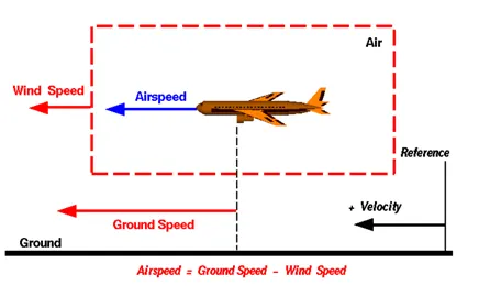
Airspeed = Ground Speed - Wind Speed |
Wind Speed
For a reference point picked on the ground, the air moves relative to the reference point at the wind speed. Notice that the wind speed is a vector quantity and has both a magnitude and a direction. Direction is important. A 20-mph wind from the west is different from a 20 mph wind from the east. The wind has components in all three primary directions (north-south, east-west, and up-down). In this figure, we are considering only velocities along the aircraft's flight path. A positive velocity is defined to be in the direction of the aircraft's motion. We are neglecting cross winds, which occur perpendicular to the flight path but parallel to the ground, and updrafts and downdrafts, which occur perpendicular to the ground.
3. Why is it not recommended to use aircraft engine power to move it on the ground at Airport?
Although many aircrafts are capable of moving in backword using reverse that , os result the jet biost or prop wash might cause damage to the terminal building or equipment Engine close forward and then suck them in ground may also blow wond ond debris Therefore there are pushbock trucks in most ports is to move the owcraft away culing damage to the engine the prout the the airport A pushbock truck is the front w from the parking spot on to the ways , which called towing
1. Effectively a loss of control can happen high power engine running Damage can occur to the aircraft itself , other aircraft nearby or to airside structures .
2. There is a risk of injury to ground support personnel who may be in relatively close proximity to the aircraft.
3. it is easier for truck driver to see the surroundings better than the pilot sitting in the cockpit with limited window . The pushback driver knows the airport better than the pilot .
4. It also saves fuel . virgin Atlantic had proposed a new system in which pushback truck will move the aircraft all the way to runway to save fuel and reduce impact of environment .
5. The plane engines are very loud . When more than one plane will add up their sound , than it will not be pleasent for passangers and others near airport
4. How an aircraft is pushed to runway when its ready to take off?
Takeoff is the phase of fight in which on aircraft goes through a transition from moving along the ground ( taxing ) to tying in the air , usually starting on a runway Usualty the engines are run ot full power during takeoff Following the taxi motion , the aircraft stops of the starting line of the runway before takeoff the engines , particularly piston engines are routinely run up ot high power to check for engine related problems . This makes a considerable noise when the pilot releases the brokes the oircroft starts accelerating rapidly until the necessary speed for take - off is achieved
The takeoff speed required varies parameters there are
1. air density
2. aircraft weight
3. aircraft configuration ( tap and / or slat position , as applicabile )
4. Air density is affected by factors such as field elevation and air temperature
A so-called pushback truck reverses the aircraft into taxiing position, pushing it with a towbar attached to the nose-wheel strut. Or, in the most modern versions, by actually lifting the wheel. That speeds up coupling and decoupling.The aircraft taxis to the runway to depart at the agreed time.
5. Learn about take off power, tyre design, rolling resistance, tyre pressure, brake forces when landing.
1. take off power
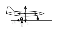
The take-off distance consists of two parts, the ground run, and the distance from where the vehicle leaves the ground to until it reaches 50 ft (or 15 m). The sum of these two distances is considered the take-off distance. (Note: sometimes a 35 ft altitude is used). The take-off distance is generally calculated for maximum weight in a standard atmosphere. In addition, usually the worst-case scenario is also calculated which is maximum weight, high altitude, and a standard “hot” day. Of immediate concern here is the calculation of the ground roll. In order to calculate the ground roll, we need to write the equations of motion for the vehicle as it moves down the runway. A free-body diagram of the vehicle is shown to the right. The forces that act on it are the aerodynamic forces of lift and drag (L and D), the thrust force (T), the ground normal force (R) and the ground friction force (R), where is the coefficient of rolling friction. We can now write the equations of motion along the runway and perpendicular to it.
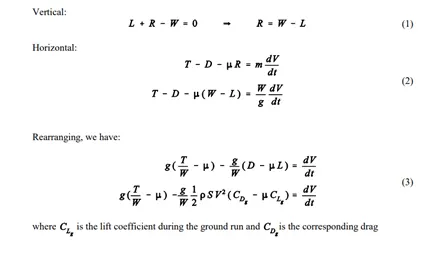
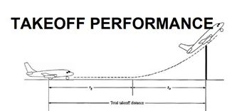
An airplane is motionless at the end of a runway. This is denoted by location O. The pilot releases the brakes and pushes the throttle to maximum take-off power, and the airplane accelerates down the runway. At some distance from its starting point, the airplane lifts into the air. The distance the airplane cover along the runway before it lifts into the air is called the ground roll (sg). The total take-off distance also includes the extra distance covered over the ground after the airplane is airborne but before it clears an obstacle of 50 ft for military aircraft and 35 ft for commercial aircraft. This is denoted by sa. The sum of sg and sa is the total take-off distance.

As the airplane accelerates from zero velocity, at some point it will reach the stalling velocity VStall
- The airplane continues to accelerate until it reaches the minimum control speed on the ground, Vmcg. This is the minimum velocity at which enough aerodynamic force can be generated on the vertical fin with rudder deflection while the airplane is still rolling along the ground to produce a yawing moment sufficient to counteract that produced when there is an engine failure for a multiengine aircraft.
- If the airplane were in the air (without the landing gear in contact with the ground), the minimum speed required for yaw control in case of engine failure is slightly greater than Vmcg This velocity is called the minirnum control speed in the air, Vmca
- The airplane continues to accelerate until it reaches the decision speed, V1. This is the speed at which the pilot can successfully continue take-off even though an engine failure (in a multiengine aircraft) would occur at this point. If an engine fails before V1 is achieved, the take-off must be stopped. If an engine fail after V1 is reached, the take-off has to be completed.
2. tyre design
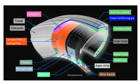
Retreading – Retreading is methods of restoring a worn tyre by renewing the tread area or by renewing the tread area plus one or both sidewalls. Repairs are included in the tyre retreading process.
Load Rating – Load rating is the maximum permissible load at a specified inflation pressure.
Ply Rating – Ply Rating is used to identify the maximum recommended load rating and inflation pressure for a specified tyre. It is an index of tyre strength.
Speed Rating – The speed rating is the maximum take-off speed to which the tyre has been tested.
Skid Depth – Skid depth is the distance between the tread surface and the deepest groove as measured in the mould.
Aircraft tyres must have an approved speed and load rating and have sufficient clearance when retracted through landing gear to allow for tyre growth. Tyre growth is the increase in the size of the tyre due to centrifugal forces at high speed.
Aircraft tyres may be Tube-type or Tubeless
Tubeless tyres are more advantageous over tube-type. There is no longer the use of tube-type tyre in recent aviation. Nowadays all airliners are using tubeless tyres. Tubeless that are meant to be used without a tube has the word TUBELESS on the sidewall of the tyre.
Aircraft tyres may be Radial or Bias
Almost all airliners are using Radial tyre. Bias is an older design, and it’s mainly used for road vehicles. Radial tyres have the word RADIAL on the sidewall. Radial tires are more expensive than bias-ply tyres. Radial tires are in demand because of their lower life cycle cost and long-term value.
Aircraft Tyre Standards
Each tyre manufacturer produces their own designs of the tyre with different tread patterns, wear patterns, wear limits etc, and in some cases, different names for the same part of the tyre. But all tyres must meet the approved standards before being accepted by the FAA or CAA.
All commercial aircraft tyres approved under FAA Requirement Technical Standard Order (TSO) C62. A TSO is a minimum performance standard for specified materials, parts, and appliances used on civil aircraft.
tyre pressure
- Tire pressure should be measured at ambient temperature. Fluctuations of ambient temperature greatly affect tire pressure and complicate maintenance of pressure within the allowable range for safe operation. Tire pressure typically changes 1 percent for every 5 °F of temperature change. When aircraft are flown from one environment to another, ambient temperature differences can be vast. Maintenance personnel must ensure that tire pressure is adjusted accordingly.
- For example, an aircraft with the correct tire pressure departing Phoenix, Arizona where the ambient temperature is 100 °F arrives in Vail, Colorado where the temperature is 50 °F. The 50° difference in ambient temperature results in a 10 percent reduction in tire pressure. Therefore, the aircraft could land with underinflated tires that may be damaged due to over-temperature from flexing beyond design limits as described above. An increase in tire pressure before take-off in Phoenix, Arizona prevents this problem as long as the tires are not inflated beyond the allowable limit provided in the maintenance data.
- When checking tire pressure, allow 3 hours to elapse after a typical landing to ensure the tire has cooled to ambient temperature. The correct tire pressure for each ambient temperature is typically provided by the manufacturer on a table or graph.
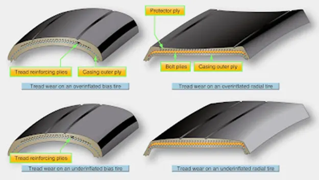
- Over inflation of aircraft tires is another undesirable condition. While carcass damage due to overheating does not result, adherence to the landing surface is reduced. Over a long period of time, over inflation leads to premature tread wear. Therefore, over inflation reduces the number of cycles in service before the tire must be replaced. It makes the tire more susceptible to bruises, cutting, shock damage, and blowout. [Figure]
rolling resistance
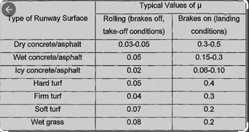
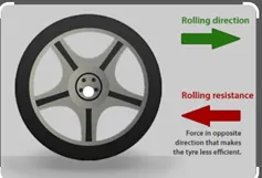
Rolling resistance, sometimes called rolling friction or rolling drag, is the force resisting the motion when a body (such as a ball, tire, or wheel) rolls on a surface. It is mainly caused by non-elastic effects; that is, not all the energy needed for deformation (or movement) of the wheel, roadbed, etc., is recovered when the pressure is removed. Two forms of this are hysteresis losses (see below), and permanent (plastic) deformation of the object or the surface (e.g. soil). Note that the slippage between the wheel and the surface also results in energy dissipation. Although some researchers have included this term in rolling resistance, some suggest that this dissipation term should be treated separately from rolling resistance because it is due to the applied torque to the wheel and the resultant slip between the wheel and ground, which is called slip loss or slip resistance. In addition, only the so-called slip resistance involves friction, therefore the name "rolling friction" is to an extent a misnomer.Analogous with sliding friction, rolling resistance is often expressed as a coefficient times the normal force. This coefficient of rolling resistance is generally much smaller than the coefficient of sliding friction.Any coasting wheeled vehicle will gradually slow down due to rolling resistance including that of the bearings, but a train car with steel wheels running on steel rails will roll farther than a bus of the same mass with rubber tires running on tarmac/asphalt. Factors that contribute to rolling resistance are the (amount of) deformation of the wheels, the deformation of the roadbed surface, and movement below the surface. Additional contributing factors include wheel diameter, load on wheel, surface adhesion, sliding, and relative micro-sliding between the surfaces of contact. The losses due to hysteresis also depend strongly on the material properties of the wheel or tire and the surface. For example, a rubber tire will have higher rolling resistance on a paved road than a steel railroad wheel on a steel rail. Also, sand on the ground will give more rolling resistance than concrete. Sole rolling resistance factor is not dependent on speed.
Types and Construction of Aircraft Brakes (Part Two)
Dual-Disc Brakes
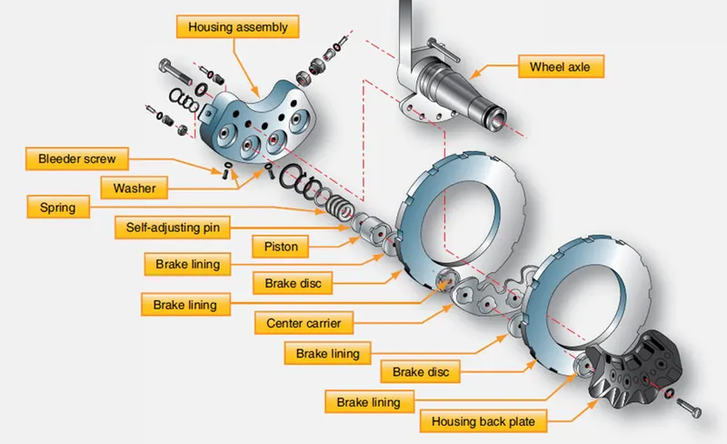
Dual-disc brakes are used on aircraft where a single disc on each wheel does not supply sufficient braking friction. Two discs are keyed to the wheel instead of one. A center carrier is located between the two discs. It contains linings on each side that contact each of the discs when the brakes are applied.
The caliper mounting bolts are long and mount through the center carrier, as well as the backplate which bolts to the housing assembly. [Figure 13-83]
Figure 13-83. A dual-disc brake is similar to a single-disc brake. It uses a center carrier to hold brake linings against each of the discs. [click image to enlarge] Multiple-Disc Brakes
Large, heavy aircraft require the use of multiple-disc brakes. Multiple-disc brakes are heavy duty brakes designed for use with power brake control valves or power boost master cylinders, which is discussed later in this chapter. The brake assembly consists of an extended bearing carrier similar to a torque tube type unit that bolts to the axle flange. It supports the various brake parts, including an annular cylinder and piston, a series of steel discs alternating with copper or bronze-plated discs, a backplate, and a backplate retainer. The steel stators are keyed to the bearing carrier, and the copper or bronze plated rotors are keyed to the rotating wheel. Hydraulic pressure applied to the piston causes the entire stack of stators and rotors to be compressed. This creates enormous friction and heat and slows the rotation of the wheel. [Figure 13-84]
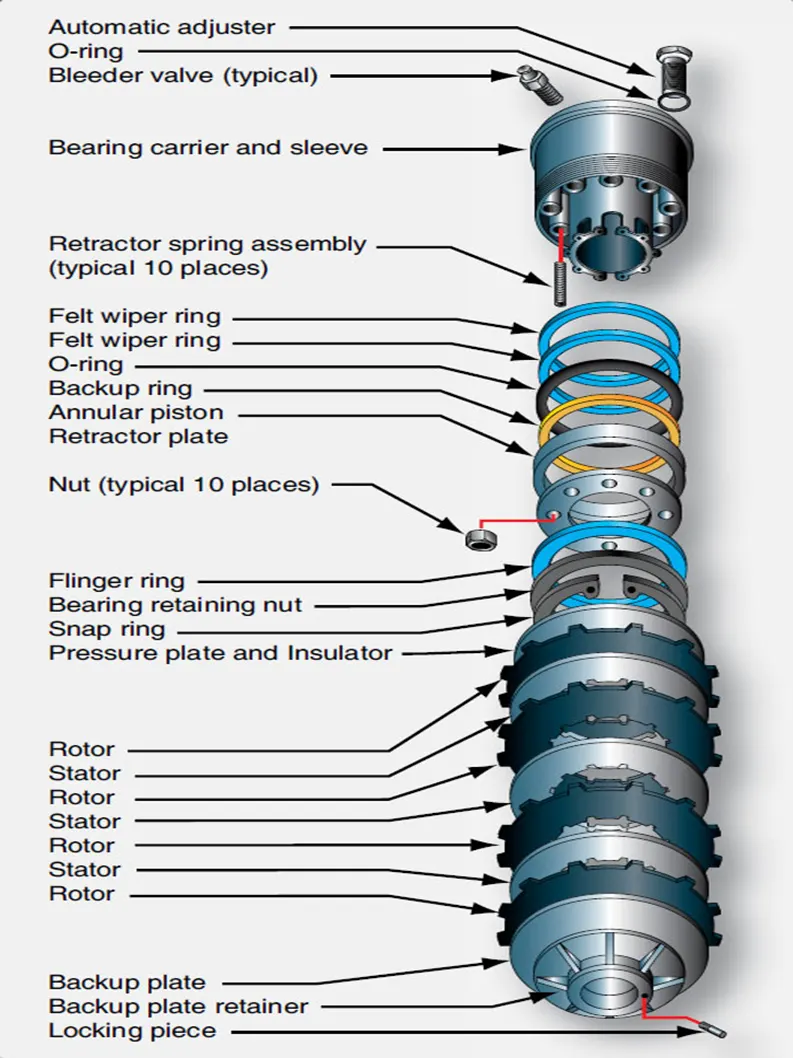
Figure 13-84. A multiple disc brake with bearing carrier upon which the parts of the brake are assembled including an annular cylinder and piston assembly that apply pressure evenly to a stack of rotors and stators.
As with the single and dual-disc brakes, retracting springs return the piston into the housing chamber of the bearing carrier when hydraulic pressure is relieved. The hydraulic fluid exits the brake to the return line through an automatic adjuster. The adjuster traps a predetermined amount of fluid in the brakes that is just sufficient to provide the correct clearances between the rotors and stators. [Figure 13-85] Brake wear is typically measured with a wear gauge that is not part of the brake assembly. These types of brake are typically found on older transport category aircraft. The rotors and stators are relatively thin, only about 1⁄8-inch thick. They do not dissipate heat very well and have a tendency to warp.
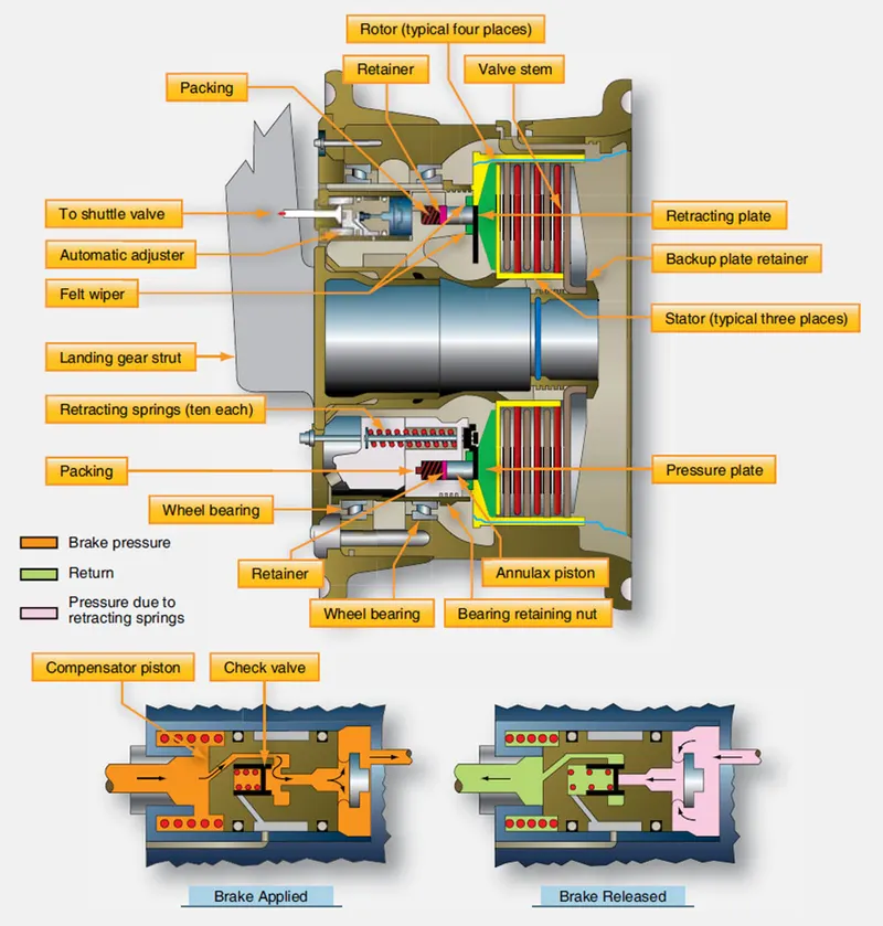
Figure 13-85. A multiple-disc brake with details of the automatic adjuster. [click image to enlarge] Segmented Rotor-Disc Brakes
The large amount of heat generated while slowing the rotation of the wheels on large and high-performance aircraft is problematic. To better dissipate this heat, segmented rotor disc brakes have been developed. Segmented rotor-disc brakes are multiple-disc brakes but of more modern design than the type discussed earlier. There are many variations. Most feature numerous elements that aid in the control and dissipation of heat. Segmented rotor-disc brakes are heavy-duty brakes especially adapted for use with the high-pressure hydraulic systems of power brake systems. Braking is accomplished by means of several sets of stationaries, high friction type brake linings that make contact with rotating segments. The rotors are constructed with slots or in sections with space between them, which helps dissipate heat and give the brake its name. Segmented rotor multiple-disc brakes are the standard brake used on high performance and air carrier aircraft. An exploded view of one type of segmented rotor brake assembly is shown in Figure 13-86.
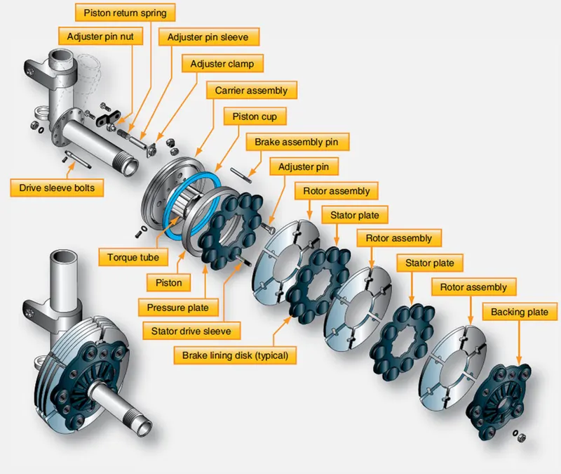
Figure 13-86. Exploded and detail views of segmented rotor brakes. [click image to enlarge] The description of a segmented rotor brake is very similar to the multiple-disc type brake previously described. The brake assembly consists of a carrier, a piston and piston cup seal, a pressure plate, an auxiliary stator plate, rotor segments, stator plates, automatic adjusters, and a backing plate.
The carrier assembly, or brake housing with torque tube, is the basic unit of the segmented rotor brake. It is the part that attaches to the landing gear shock strut flange upon which the other components of the brake are assembled. On some brakes, two grooves or cylinders are machined into the carrier to receive the piston cups and pistons. [Figure 13-86] Most segmented rotor-disc brakes have numerous individual cylinders machined into the brake housing into which fit the same number of actuating pistons. Often, these cylinders are supplied by two different hydraulic sources, alternating every other cylinder from a single source. If one source fails, the brake still operates sufficiently on the other. [Figure 13-87]
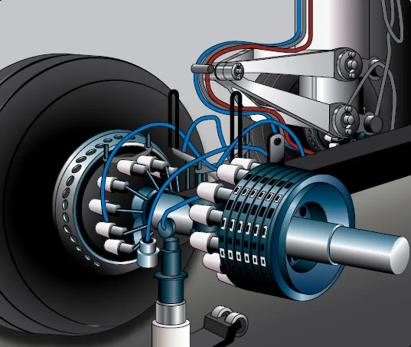
Figure 13-87. Many modern segmented rotor disc brakes use a housing machined to fit numerous individual actuating pistons.
External fittings in the carrier or brake housing admit the hydraulic fluid. A bleed port can also be found.
A pressure plate is a flat, circular, high-strength steel, nonrotating plate notched on the inside circumference to fit over the stator drive sleeves or torque tube spines. The brake actuating pistons contact the pressure plate. Typically, an insulator is used between the piston head and the pressure plate to impede heat conduction from the brake discs. The pressure plate transfers the motion of the pistons to the stack of rotors and stators that compress to slow the rotation of the wheels. On most designs, brake lining material attached directly to the pressure plate contacts the first rotor in the stack to transfer the motion of the piston(s). [Figure 13-86] An auxiliary stator plate with brake lining material on the side opposite the pressure plate can also be used.
Any number of alternating rotors and stators are sandwiched under hydraulic pressure against the backing plate of the brake assembly when the brakes are applied. The backing plate is a heavy steel plate bolted to the housing or torque tube at a fixed dimension from the carrier housing. In most cases, it has brake lining material attached to it and contacts the last rotor in the stack. [Figure 13-86]
Stators are flat plates notched on the internal circumference to be held stationary by the torque tube spines. They have wearable brake lining material riveted or adhered to each side to make contact with adjacent rotors. The liner is typically constructed of numerous isolated blocks. [Figure 13-86] The space between the liner blocks aids in the dissipation of heat. The composition of the lining materials varies. Steel is often used.
Rotors are slit or segmented discs that have notches or tangs in the external circumference that key to the rotating wheel. Slots or spaces between sections of the rotor create segments that allow heat to dissipate faster than it would if the rotor was solid. They also allow for expansion and prevent warping. [Figure 13- 86] Rotors are usually steel to which a frictional surface is bonded to both sides. Typically, sintered metal is used in creating the rotor contact surface.
Segmented multiple-disc brakes use retraction spring assemblies with auto clearance adjusters to pull the backplate away from the rotor and stator stack when brake pressure is removed. This provides clearance so the wheel can turn unimpeded by contact friction between the brake parts, but keeps the units in close proximity for rapid contact and braking when the brakes are applied. The number of retraction devices varies with brake design. Figure 13-88 illustrates a brake assembly used on a Boeing 737 transport category aircraft. In the cutaway view, the number and locations of the auto adjustment retraction mechanisms can be seen. Details of the mechanisms are also shown.
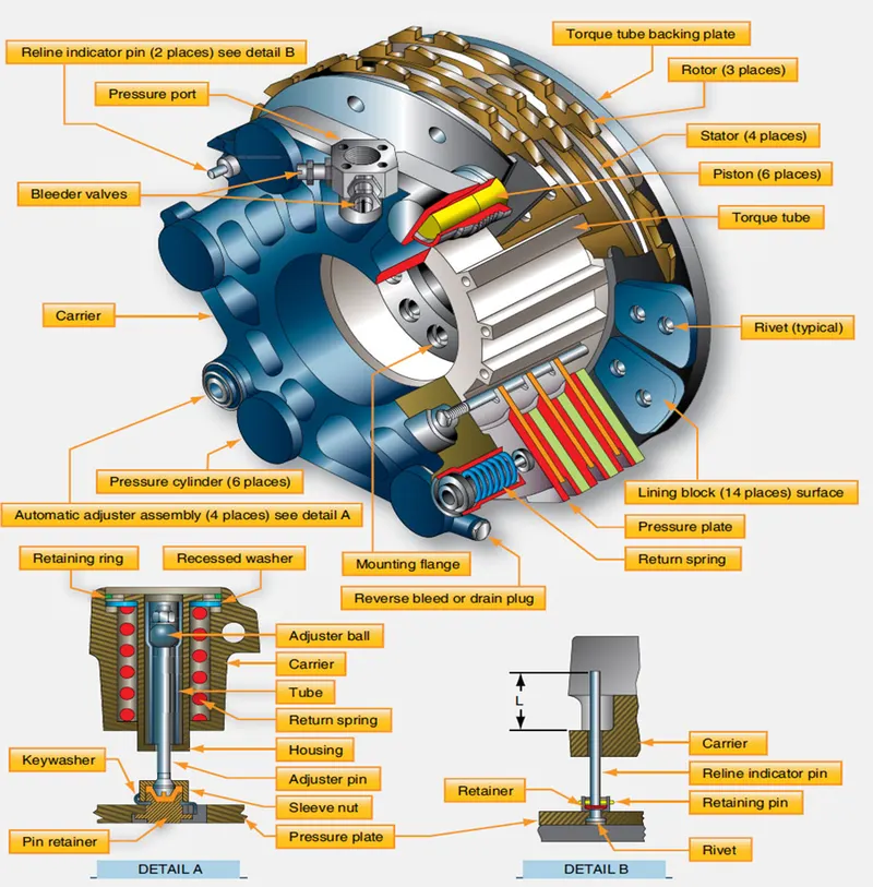
Figure 13-88. The multiple-disk brake assembly and details from a Boeing 737. [click image to enlarge] Instead of using a pin grip assembly for auto adjustment, an adjuster pin, ball, and tube operate in the same manner. They move out when brake pressure is applied, but the ball in the tube limits the amount of the return to that equal to the brake lining wear. Two independent wear indicators are used on the brake illustrated. An indicator pin attached to the backplate protrudes through the carrier. The amount that it protrudes with the brakes applied is measured to ascertain if new linings are required.
NOTE: Other segmented multiple-disc brakes may use slightly different techniques for pressure plate retraction and wear indication. Consult the manufacturer’s maintenance information to ensure wear indicators are read correctly.
7.A. With necessary assumptions, calculate the force and power required to push / pull an aircraft by a towing vehicle.
calculate the force and power required to push / pull an aircraft by a towing vehicle.
the three force acting on vehicle there are
1. rolling resistance
2. hill clamping
3. areodynamic drag
1. rolling resistance force:
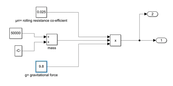
`Frr=μrr*m*g`
here Frr= rolling resistance
μrr= rolling resistance co-efficient
m= mass
g= gravitational force
2. hill clamping force
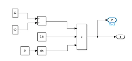
`Fhc=m*g*sin(φ)`
Fhc = hill clamping force
m= mass
g= gravitational force
sin(φ)= angle slop
3. aerodynamic drag force:
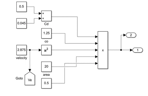
`Fab = 1/2* ρ*A*Cd*v^2`
Fab= aerodynamic drag force
ρ=air density
A = frontal area
Cd= drag co-efficient
V= Velocity
parameter assumed;
vehicle mass:50000kg
payload mass:183700kg
gravitational force: 9.8m/s^2
frountal area: 20m^2
sin(φ): 0
μrr:0.025
ρ=1.25
Cd=0.5 and 0.045
V= 2.875 m/s
1. rolling resistance force:
`Frr=μrr*m*g`
=0.025*9.8*(50000+183700)
=0.025*9.8*(233700)
=57256.5 N
2. hill clamping force
`Fhc=m*g*sin(φ)`
=9.8*(50000+183700)*0
= 0
3. aerodynamic drag force:
`Fab = 1/2* ρ*A*Cd*v^2`
= 1/2*1.25*20*(0.5+0.045)*2.875^2
=56.309 N
TOTAL FORCE REQUIRED Fte=Frr+Fhc+Fab
=57256.5+0+56.309
=57312.8096N
= 57.312 KN
TOTAL POWER REQUIRED = Fte*V
=57.312*2.875
= 164.774KW
7.b.Develop the model for the calculated force and power using Simulink.
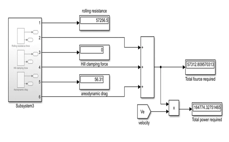
the above fig shows the model of calculation of total power required and total force required to pull/push aircraft
1. rolling resistance subsystem shown below
2. Hill clamping force subsystem shown below
3. Aerodynamic drag
the as per mode total power require to pull and push vehicle is 164kw and force required is 57.312kN
7. A. Design an electric powertrain with type of motor, it’s power rating, and energy requirement to fulfill aircraft towing application in Simulink. Estimate the duty cycle range to control the aircraft speed from zero to highest. Make all required assumptions. Prepare a table of assumed parameters. Draw a block diagram of powertrain.
(Hint :DC7 Block)
from problem we solved the the power required
energy =power*time
we consider that time =0.45h assumed
and power should be taken as =164kw
energy output =power*time
=164*0.45
=73.8kwh
the duty cycle =power output/power input
the power input can be calculate by assumed vallues
input current=500a
input voltage= 540v
powerinput = input current*input voltage
= 500*540
=2600000
=260kw
duty cycle= powerout/power input
=164/260
=0.63
=63.07%
duty cycle required by the towing vehicle= 63.07%
Prepare a table of assumed parameters
| kerb weight | kg | 183700 |
| towing vehicle | kg | 50000 |
| coefficient of rolling resistance | 0.025 |
| Air density | kg/m^3 | 1.25 |
| width towing vehicle | m | 3.4 |
| height towing vehicle | m | 2 |
| width aircraft | m | 15.8 |
| height aircraft | m | 43.9 |
| drag coefficient | 0.6 | |
| speed | kmph | 2.875 |
| gravitational force | m/s^2 | 9.80 |
the below fig shows the the four quadrant chopper 200hp dc drive
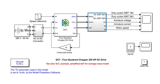
The 200 HP DC motor is separately excited with a constant 150 V DC field voltage source. The armature voltage is provided by an IGBT converter controlled by two PI regulators. The converter is fed by a 515 V DC bus obtained by rectification of a 380 V AC 50 Hz voltage source. In order to limit the DC bus voltage during dynamic braking mode, a braking chopper has been added between the diode rectifier and the DC7 block.
The first regulator is a speed regulator, followed by a current regulator. The speed regulator outputs the armature current reference (in p.u.) used by the current controller in order to obtain the electromagnetic torque needed to reach the desired speed. The speed reference change rate follows acceleration and deceleration ramps in order to avoid sudden reference changes that could cause armature over-current and destabilize the system. The current regulator controls the armature current by computing the appropriate duty ratios of the 5 kHz pulses of the four IGBT devices (Pulse Width Modulation). For proper system behaviour, the instantaneous pulse values of IGBT devices 1 and 4 are opposite to those of IGBT devices 2 and 3. This generates the average armature voltage needed to obtain the desired armature current. In order to limit the amplitude of the current oscillations, a smoothing inductance is placed in series with the armature circuit.
the output shown below.
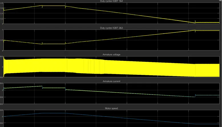
1st and 2nd graph show the IGBT output and 3rd graph shows the armature voltage and 4ht shows the armature current and last one show the speed
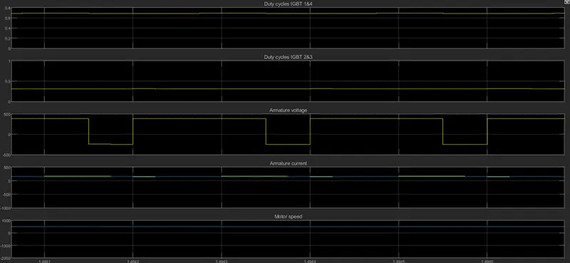
the above graph shows the zoomed version of output.
B. Also, Design the parameters in excel sheet.
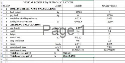
for the above parameter consider for calculation that same value should taken for excle calculation.