Project-1: Powertrain for aircraft in runways
PROJECT: POWERTRAIN FOR AIRCRAFT IN RUNWAYS
AIM OF THE PROJECT:
- Detailed overview of air-craft and its parts.
- Modelling and estimation of necessary parameters required to control the motion of air-crsft in runways.
- Observing the behaviour of air-crafts motion on ground and during take-off.
OBJECTIVE:
- 1. Search and list out the total weight of various types of aircrafts.
- 2. Is there any difference between ground speed and air speed?
- 3. Why is it not recommended to use aircraft engine power to move it on the ground at Airport?
- 4. How an aircraft is pushed to runway when its ready to take off?
- 5. Learn about take off power, tyre design, rolling resistance, tyre pressure, brake forces when landing.
- 6. A. With necessary assumptions, calculate the force and power required to push / pull an aircraft by a towing vehicle.
- B. Develop the model for the calculated force and power using Simulink.
- 7. A. Design an electric powertrain with type of motor, it’s power rating, and energy requirement to fulfill aircraft towing application in Simulink. Estimate the duty cycle range to control the aircraft speed from zero to highest. Make all required assumptions. Prepare a table of assumed parameters. Draw a block diagram of powertrain.
(Hint :DC7 Block)
- B. Also, Design the parameters in excel sheet.
Solutions:
STUDY 1:> As we know that,weight is the force generated by the gravitational attraction of the earth which we can estimate by the given formulla w=m*g,where w = is the weight,m = is the mass,g = is the gravvitational constants ,g = 9.8m/sec^2 or 32.2ft/sec^2.In case of a whole air-craft there are different parts and each part of the air-craft bears a unique weight and mass example: the wings,the engine,the payload,and the fuel.The mass of the individual components can be calculated if we know the size of the components and its chemical composition example:iron,plastic,almunium,gasoline etc.Therefore the total weightr of the air-craftis the sum of the individual components given as:
W = w(Fuselage)+w(Payload)+w(Engines)+w(Wings)+...
It can be pictured as:-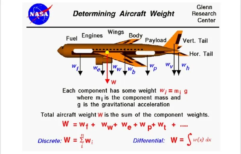
Center o fgravity (CG) of an air-craft is calculated as follows:
- Determine the weights and arms of all mass within the air-craft.
- Multiply weights by arms for all mass to calculate moments.
- And the moments of all mass together.
- Divide the total moment by the total mass of the air-craft to give on overall arm
The arm that results from this calculation must be within the center of gravity limits dictated by the air-craft manufacturer.If it is not,weight in the air-craft must be removed,added(rarely) or redistributed until the center of the gravity falls within the pescribed limits.
Air-craft center of the gravity calculations are only performed along a single axis from the zero point of the reference datum that represents the longitudinal axis of the air-craft ( to calculate the fore-to-aft balance).Some helicopter types utilize lateral CG limits as well as longitudianal limits.Operation of such helicopters requires calculating CG along two axes: One calculational for longitudianal CG (fore-to-aft balance) and another calcualtion for lateral CG (left-to-right balance).
The weight,moment & arm values of fixed items on air-craft (i,e.engines,wings,electronic components) do not change and are provided by the manufacturer on the Air-craft Equipment List.The manufacturer also provides information facilitating the calculation of moments for fuel loads.Removable weight items (i,e. crew members,passengers,baggage) must be properly accounted for in the weight and CG calculation by the air-craft operator.
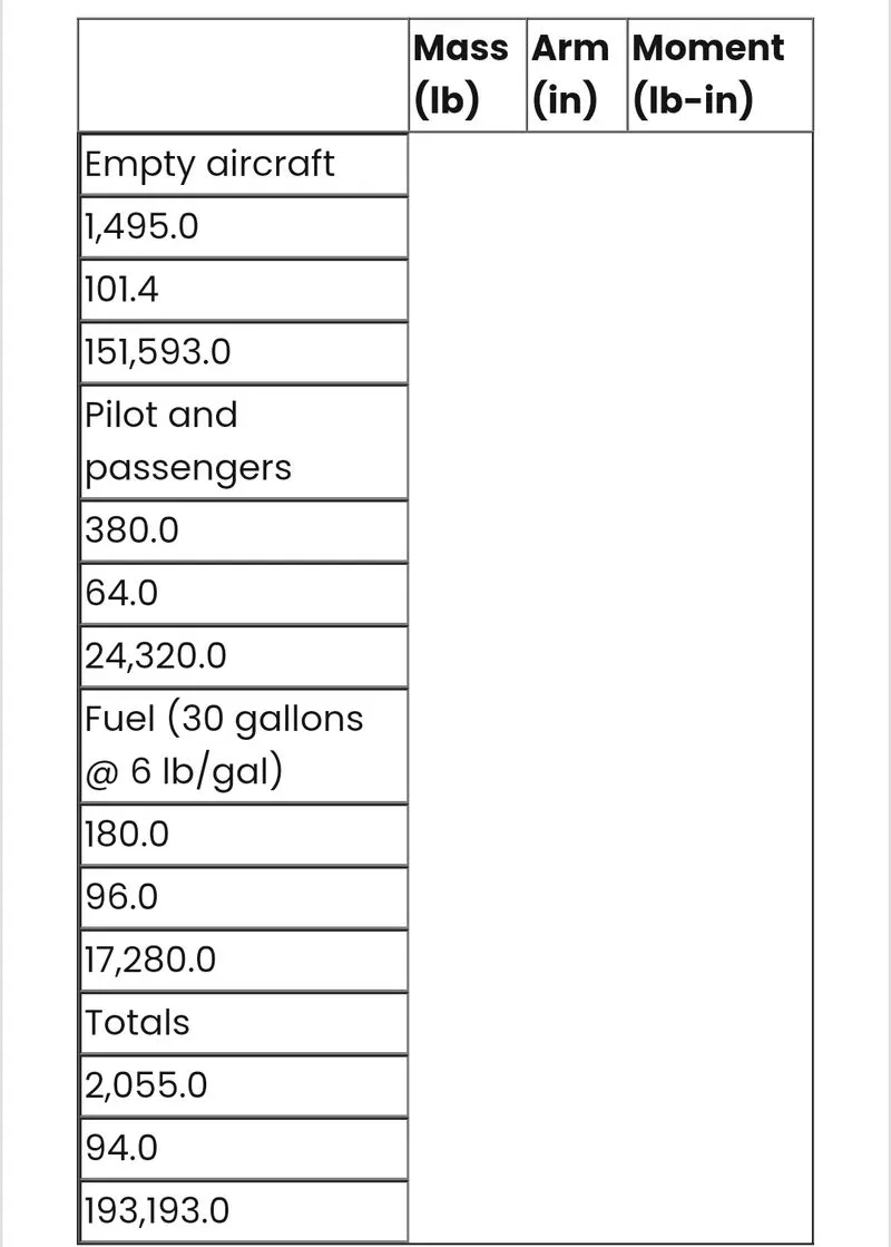
To find the center of the gravity,we divide the total moment by the total mass : 193,193/20,55 = 94.01 inches behind the datum plane.
Air-craft authorised gross weight is defined as the total aircraft weight at any moment during the flight and grounding operation.The authorised weight limits that can be legally be used by any operator or airline are listed in the AFM and the weight and the balance manual.They are also reffered as purchased weights.
The classification of different types of weight under gross weight can be mad ein the following categories:
- Maximum Ramp Weight (MRW):-
It is defined as the maximum weight authorised for taxing and towing on t eground as limited by air-craft strength or airworthiness requirements.The differernce between the maximum ramp weight and the maximum take-off weight depends on the size of the air-craft,the number of engines,APU operation and engine fuel consumption.Which is typically assumed for 10-15 minutes of taxing,towing of run-up operation.
- Maximum Take-Off Weight (MTOW):- It is defined as the maximum certified design weight for take-off run as limited by air-craft strength an dairworthiness requirement.The maximum take-off weight is always less than the maximum ramp weight to allow fuel burned during taxi by th eengines and the APU.
- Maximum Landing weight(MLW):- It is defined as the maximum design certified weight for normal landing gear strength or the landing impact loads on certain parts of the wing and chassis structure.
- MDLW<MDTW<MRW
- Maximum Zero Fuel Weight:- The maximum zero fuel weight is the maximum certified on the air-craft without the usable fuel and others limited by air-craft strength and airworthiness requirements.In other words it is the maximum weight permitted before the usable fluid and other usable items are loaded in the air-craft.
- Operational Empth Weight (OEW):- The OEW is fixed for a specific air-craft and inly gets changed during operational changes and maintenance.OEW is the empty weight that is used in flight simulator or usual planning software.
- Actual Zero Fuel Weight (AZFW):- If we add the payload to teh empty plane weight then we get the actual zero fuel weight.Basically the payload includes the passenger luggage weight and cargo weight given by the following relationship.
- Minimum Flight Weight (MFW):- Minimum certified weight for flight as limited by air-craft strength and airworthiness requirements.The total weight of an air-craft includes aircraft's empth weight + payload.
- Aircraft's Empty Weight:- The air-craft weight with fuel left in tank + engine + other operating fluids.
- Payload:- The fuel weight + passengers weight + other operating fluids.
Operational empty weight (OEW) + Payload = Actual Zero Fuel Weight (AZFW).
Air-craft Type:
Maximum take-off weight (Kg)
Maximum fuel(Kg)
Boeing707-320
151500
72503
Boeing747-200
52610
14520
AirbusA300-B4
165000
46654
Boeing757-200
115650
36260
DouglasDC-8-32
14000
31020
Boeing737-900
79016
20894
AirbusA340-600
368000
156487
The embraer Phenom 300
8000
1545
Different Air-crafts and respective weights.
STUDY:> AIR-SPEED Vs GROUND-SPEED.
Ground speed: It is the horizontal speed of an air-craft relative to the ground.An air-craft heading vertically would have a ground speed of zero.Ground speed can be detrermined by the vector sum of the air-craft's true airspeed and the wind speed and the direction of te motion.
Wind speed: If we pick a reference point on the ground,the air moves to the reference point at the wind speed.A positive velocity is defined in th edirection of the air-craft's motion.
Airspeed: The important part in the generation of lift of air-craft is te relative velocity between the object an dthe air,which is called air-speed.It cannot be directly measured from the ground position,it is computed from the ground difference between the ground speed and the wind-speed.
As we know that the air-craft usually operates in ground as well as in air.So,the ground speed and air-speed usually changes based on the wind components.If we consider that there is no wind component then,ground speed = air-speed.if the wind is blowing in the tail-direction of the air-craft than air speed is greater than wind speed(air-speed=ground-speed + wind-speed).If the wind is blowing in the head direction of the air-craft then air-speed is less than ground-speed.So,air-speed = ground speed - wind speed.Gravity also plays a major role in increasing the air-crafts speed while it's decending.If the measured air-speed is greater than observed ground speed then the wind speed becomes positive.Here wind-speed is the vector difference between ground and air-speed.If in case the wind is zero it is equal to ground-speed.
STUDY 3:> Why is it not recommended to use aircraft engine power to move it on the ground at Airport?
- A new system was proposed where a new system where a pushback truck will move the air-craft all the way to run-way to save fuel an dreduce impact of environment.
- The plane engines are very loud,when more than one plane will add up their sound,then i twill be unbearable for passengers and other parts near airport.
STUDY 4:> How an aircraft is pushed to runway when its ready to take off?
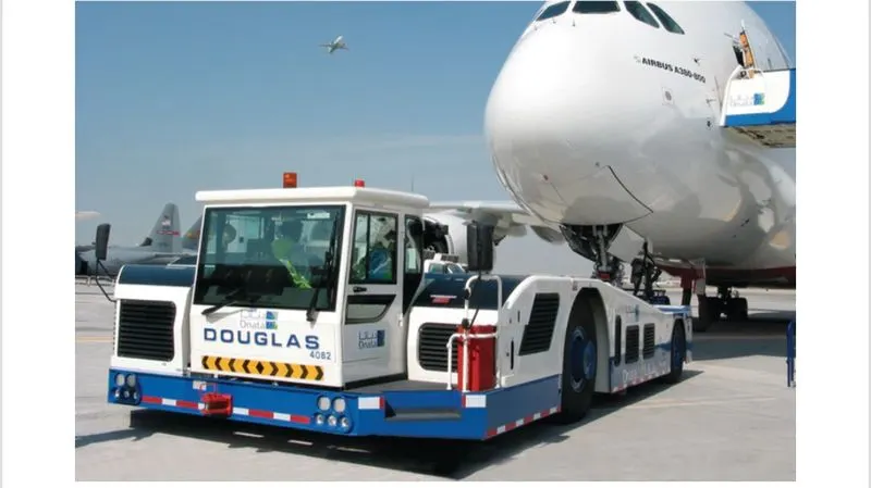
TAXIING:
It is defined as teh moment of air-craft on the ground,under its own power where a stowing or pushback is where the air-craft is moved by the tug.The air-craft usually moves on wheels but the term also used for the air-craft that has skies or floting equipments.An airplane uses taxiways to taxi from one-place on the airport to another,example when the air-craft moves from the hanger to the runways.
Towing:
Movements of large air-craft about teh airport,flight line,and hanger is usually accomplished by towing with a towing tractor (sometimes called a "tug").In the case of small air-craft,some moving is accomplished by hand pushing on the correct areas of the air-craft.Air-craft may also be taxied about the flight line usually only by certain qualified personnel.
Towing air-craft can be a hazardous operation,causing damage to the air-craft and injury to the personnel,If done reckressly or carelessly.However,specific instructions for each model of air-craft are detailed in the manufacturer's maintenance instructions and are to be followed in all instances.When towing the air-craft,teh towing vehicle speed must be reasonable,and all persons involved in the operation must be alert.When the air-craft is stopped,donot rely upon the brakes of teh towing vehicle alone to stop the air-craft.The person in the flight deck must co-ordinat ethe use of te air-craft brakes with those of the towing vehicle.
STUDY 5 :>
TAKE-OFF POWER:
In the case of light air-craft full power is used during take-off and in large air-crafts like airlines use a reduced level power to take-off,where less than full power is used to prolong the engine durability.Before take-poff the position engines are run rouyinely at high power to check engine related problems.The noise is raised to a nominal 5 - 15 degree nose up pitch altitude to increase lift from the wing sand effect lift off.The take-off power is controlled in such a way that it can cover 35 feet screen hight plays in the take-off.The pilot needs to look around different distances that affect the take-off performance which are:
TAKE-OFF RUN AVAILABLE (TORA): The distance from which the air-craft can start its take-off run to the point till the end marking for surface change.
- THE CLEARWAY: This is the area of the end of the TORA that is free from the buildings,trees or any other obstractions.The air-craft can use this area to achieve 35 feet screen height.
- ACCELERATE-STOP DISTANCE AVAILABLE (ASDA): THe final distance that muist be considered for take-off performance is the ASDA,this distance of weight bearing surface is availabe to the air-craft to accelerate and then come to stop in case of emergency.
- Take-off power = Force*Displacement i.e, (m*dv/dt)*2*s1 => (T-D-F)S1, Where S is the runway length.The force involved are T = thrust of the propulsion system,D = aerodynamic drag whic the vehicle resists,F = rolling resistance due to contavt on wheels on the gronud.
TIRE DESIGN:
The tire design of an air-craft may seems a challanging job,because the tire has to withstand heavy loads while landing,take-off,taxiing and parking .The number of wheels required for an air-craft increases as the weight of the air-craft increases cause it should be distributed evenly.The tire generates a lot of heat during landing because it drags the wheel to match its momentum.The tire is designed in such a way that it withstand hugh crosswind conditions,extreme pressure and to prevent hydroplanning and for increased braking effects.
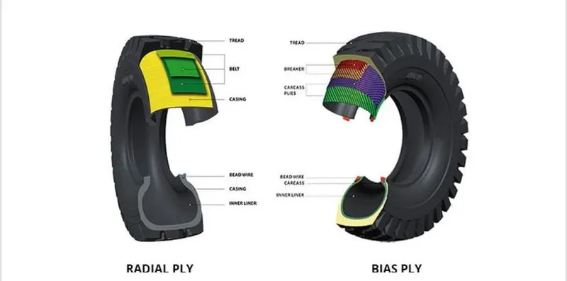
There are two types of construction of tires which are:
1. Radial Tire: It has fiber stands of the poly fabric qt 90 degree to the direction of rotation and the tire side wall.This restricts flexibility of the bidirectional side wall while it strengthnes the tire to carry heavy loads.Due to their unique construction radial tires are resistent to penetration and cuts.Due to stiffer threads they distribute weight evenly.Thus provides greater tractiion and helps in preventing heat.
2. Bias Tire: It has the fabric bias oriented with an dcross the directoion of rotation and the side-wall.Since the fabric stretches,the tire is flexible and can absorb loads,the cut resistnt area is the side-wals,strength is obtained by adding piles,these tires doesn't absorb heat well.
Rolling Resistance:
It is defined as teh force resisting the motion when a body rolls on a surface(ex-ball,tire).Rolling resistance can be seen in an air-craft when te air-craft takes-off from the runway and while landing on the runway.
Rolling resistance force can be written as :
Frr =urr*m*g (N)
Where,
urr = coefficient of the resistance
Frr = Rolling Resistance
g = Acceleration due to gravity (9.81m/s^2)
Tire Pressure:
The tires of an air-craft have withstand very high amounts of pressure,while taking-off,landing,towing,taxing.As teh weight of the air-craft increases the number of wheels aslo increased.As we know while landing teh air-craft drags the wheel till it matches with its rotational velocity,due to this a lot of heat us generated due to friction.Air-craft tires are usually filled with nitrogen to minimize expansion and contraction from changes in temperature and pressure during flight,also the use of inert gasses for tire inflation reduces the possibility of tire explosion.Services should ber done regularly by checking tire pressures and maintaining proper tire inflation pressure.
Rolling resoistance and tire pressure are inversenly proportional to each other.
Brake devices used during landing:
- Wheel brake(Anti-skid and Auto-brakes): Air-craft have highly engineered,multi disc brakes made of a carbon steel material.Manufacturers include Honeywell and goodrich,parts of collins Aerospace.In general the brakes are composed of discs that rotates with the wheel and seperate discs that are fixed.When pressure is applied from the right fixed disc on all the discs the entire assembly compresses to create the braking action.Carbon brakes are standard today;thay cool faster than steel brakes (their predecessor) and can weigh upto 700 pounds l;ess.For the initial part of the braking,say down to around 70 knots,we let the auto brakes do the job,but after that we have to come on to the brakes to disengage the autobrakes.The transition from auto brakes can be quite difficult to do smoothly especially in a cross wind,as you will be steering the air-craft with the rudder pedals and then have to press down on the tops of the rudder pedals evenly to deactivate the auto brakes and start manual braking.
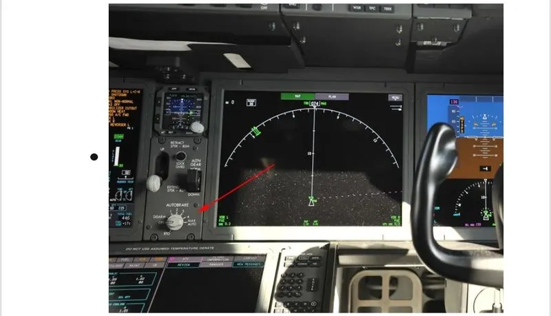
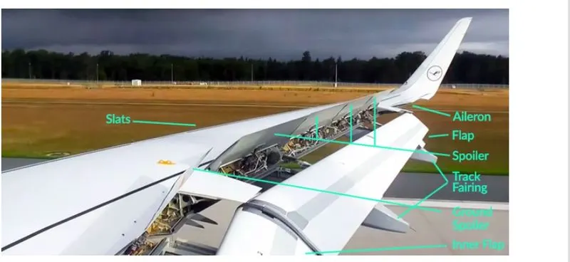
- Spoilers: When the wheels touch the ground,a set of spoilers raise upm quickely,which kills the lift provided by the wings.(There are two sets seen in the image below:ground spoilers that only deploy on landing,and spoilers that are used in flight as speed brakes as well as landing).While the spoilers provide some drag.their primary purpose is to stop the plane from actually flying,putting all off the weight on the landing gear and in turn making the brakes that much more effective.
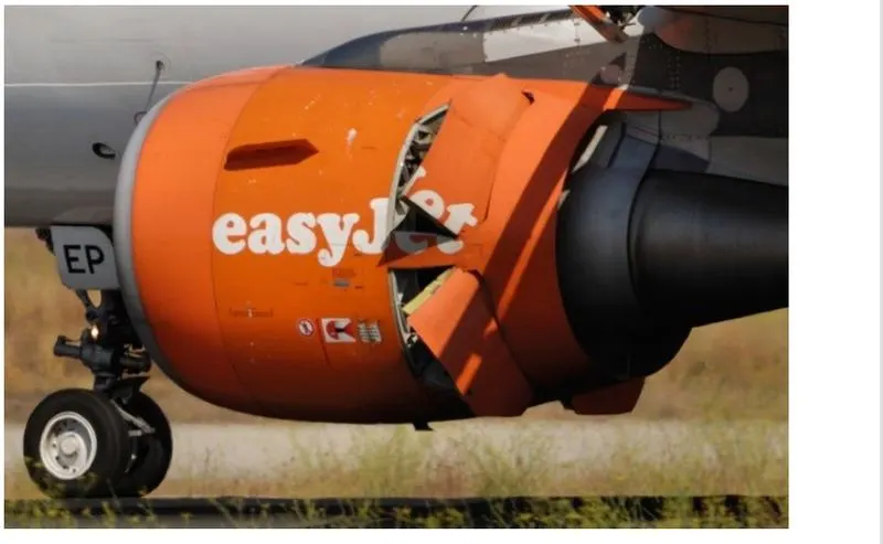
- Reverse Thrust: The final element of braking action is the thrust reversers.In a modern high-bypass turbofan engine,a full 90% of the air passing through the engine is simply sucked in,speed up and pushed uot of the engine with out mixing the fuel.In these engines,ducts on the side of the engine open up and direct thatt air out and nearly forward,opposite the direction of travel.This is called a cold-stream reverse thrust,and is part of the engine design of most modern engines.(You may have also clam-shell style reverse thrusters on older air-craft,which cup the back of the engine).
STUDY 6:> A. With necessary assumptions, calculate the force and power required to push / pull an aircraft by a towing vehicle.
B. Develop the model for the calculated force and power using Simulink.
Solution: Considering the parameters for airbus A380,assumed towing vehicle weight 1000 kg.
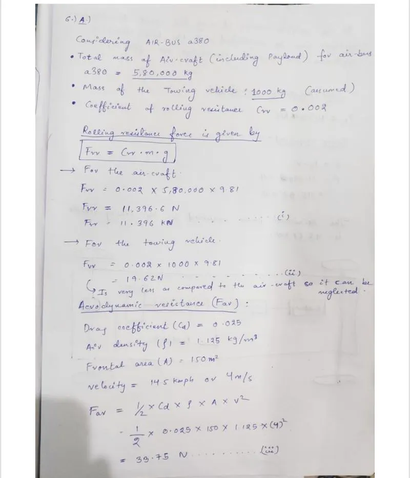
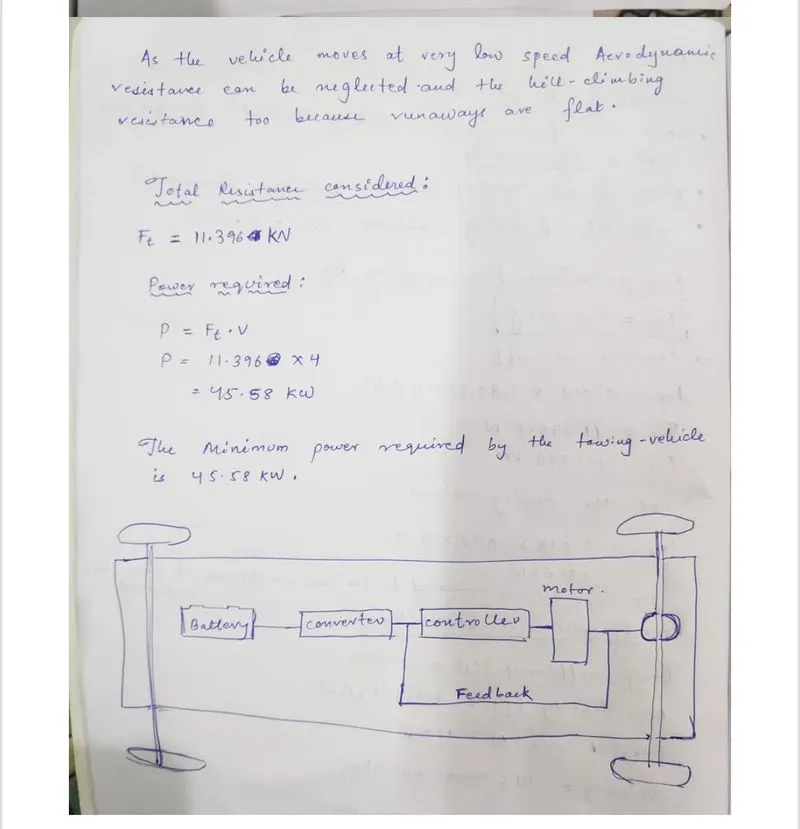
Here the minimum power required for the towing vehicle to push/pull a air-craft of the given specifications is 45.60Kw.So we took the above assumed parameters and developed a simulink model.
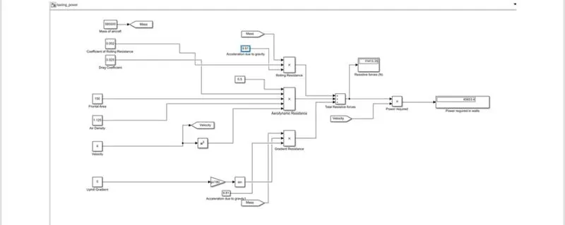
- Here we see that the otput in the diaplay is 45.653Kw.
- Constant blocks are used to feed the parameters such as mass.coefficient and others.
- Using sum block total resistant forces that are calculated.
- Display is used for visuals.
STUDY 7:>
- Design an electric powertrain with type of motor, it’s power rating, and energy requirement to fulfill aircraft towing application in Simulink. Estimate the duty cycle range to control the aircraft speed from zero to highest. Make all required assumptions. Prepare a table of assumed parameters. Draw a block diagram of powertrain.
- Also, Design the parameters in excel sheet.
Solution:
SIMULINK MODEL OF POWERTRAIN OF AN AIR_CRAFT TOWING VEHICLE:
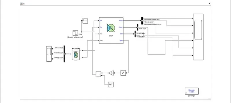
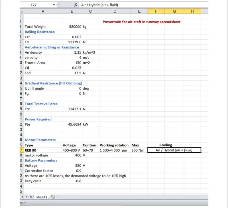
Estimation of Duty cycle: As we know that the power required for towing vehicle to push/pull is equal to 45.60 kw.For this model we have considered the motor REB 90 for drive train.
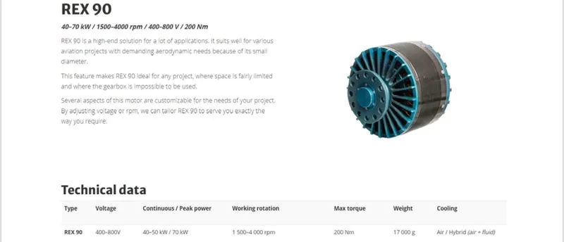
Considering 60 Kw as contineous power,so the voltage will be 400V.Battery is considered to be 550V.We know that duty cycle is given by d=Vo/vb.d=400/550,=>0.7272.There will also be losses due to teh reisistance of FET and inductance.Correction factor is considered to be 90%,that makes us consider that there is 10% loss,so the voltage which is demanded by the motor should be 10% more than the required voltage.[d=0.7272*(1+1.0)=0.799~0.8].So here the voltage demand is 440V from the battery.
Mass of the air-craft
5,80,000 kg
Mass of Towing
1000 kG
Coefficient of rolling resistance
0.002
Drag coefficient
0.025
Air-density
1.125Kg/m^3
Frontal area\
150 m^2
Velocity
4m/s
uphill gradient0 degree
Battery Voltage
550V
Correction Factor
0.8
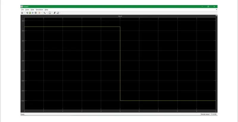
INPUT:
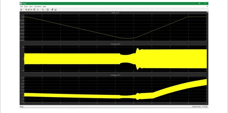
OUTPUT FROM THE BATTERY:
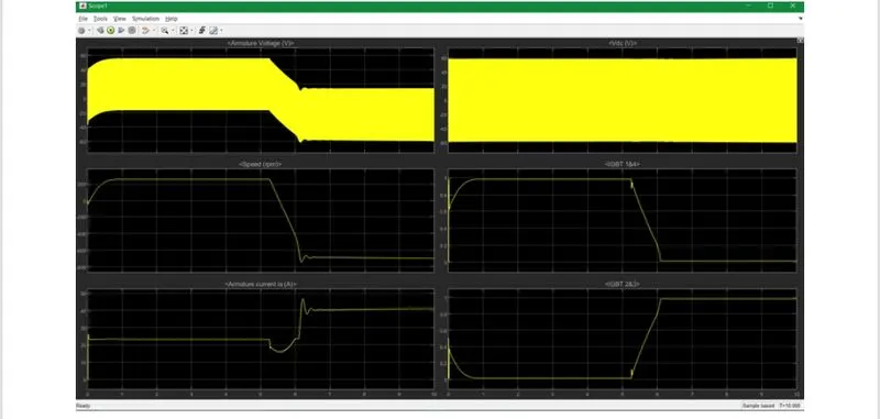
OUTPUT FROM THE MOTOR:
After simulating the model the parameters are atsted in excel sheet :
Google drive link for my models and excel sheet:
https://drive.google.com/drive/folders/1jMHkgEDvTXdft2yKcQA-FhOl3CnygzF4