Project-1: Powertrain for aircraft in runways
Q1. Search and list out the total weight of various types of aircrafts.
Ans 1:
Total weight of various types of aircrafts:
Manufacturer's empty weight is the weight of the aircraft "as built" and includes the weight of the structure, power plant, furnishings, installations, systems and other equipment that are considered an integral part of an aircraft.
This excludes any baggage, passengers, or usable fuel2.
- Zero-fuel weight(ZFW)
Zero-fuel weight is the total weight of the airplane and all its contents (including unusable fuel), but excluding the total weight of the usable fuel on board. As a flight progresses and fuel is consumed, the total weight of the airplane reduces, but the ZFW remains constant.
Maximum zero fuel weight (MZFW) is the maximum weight allowed before usable fuel and other specified usable agents (engine injection fluid, and other consumable propulsion agents) are loaded.
- Operating empty weight(OEW) (Roughly equivalent to basic empty weight on light aircraft)
Operating empty weight is the basic weight of an aircraft including the crew, all fluids necessary for operation such as engine oil, engine coolant, water, unusable fuel and all operator items and equipment required for flight but excluding usable fuel and the payload.
- Maximum takeoff weight(MTOW)
This is the maximum weight at which the pilot of the aircraft is allowed to attempt to take off3.
It is the carrying capacity of an aircraft. It includes cargo, people, extra fuel. In the case of a commercial airliner, it may refer only to revenue-generating cargo or paying passengers.
- Regulated takeoff weight(RTOW)
Depending on different factors (e.g. flap setting, altitude, air temperature, length of runway), RTOW or maximum permissible takeoff weight varies for each takeoff. It can never be higher than MTOW. More information is on this answer.
This maximum weight at which an aircraft is permitted to land3.
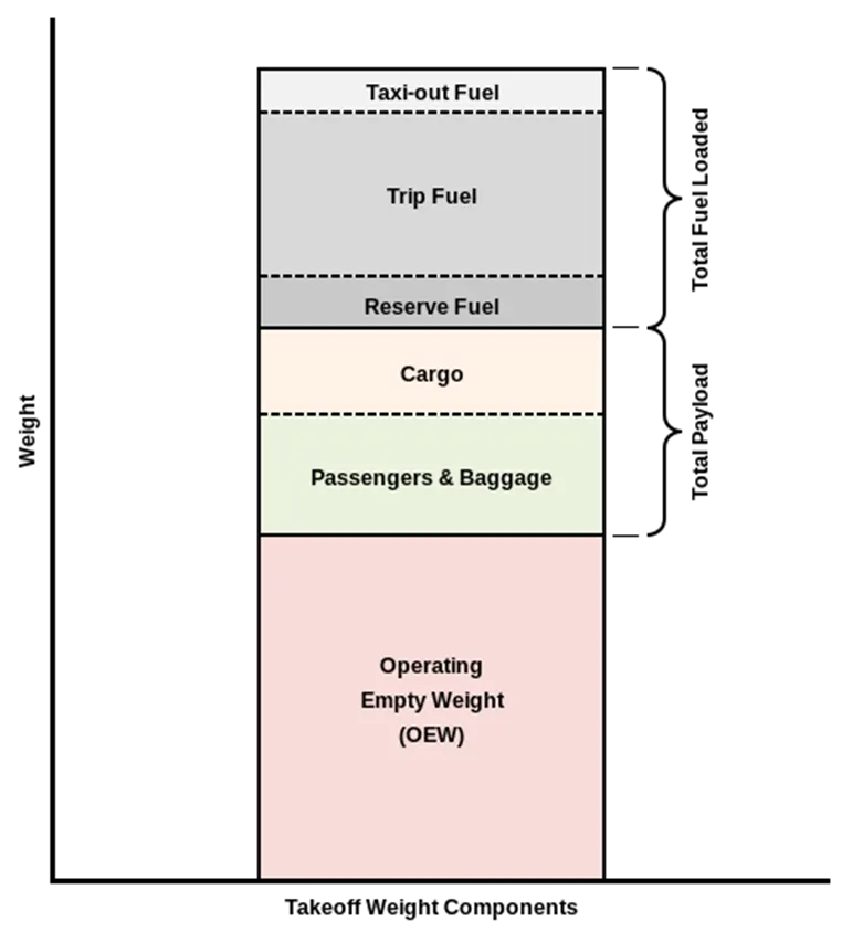
The following image depicts takeoff weight components.
- Maximum ramp weight(MRW)
also called maximum taxi weight (MTW)
It is the maximum weight authorized for maneuvering (taxiing or towing) an aircraft on the ground.
It is the total aircraft weight at any moment during the flight or ground operation. This decreases during flight due to fuel and oil consumption.
Typical Airplane Weights
Below is a table of some of the most common aircraft flying around our skies today:
|
Aircraft |
Empty Weight |
Max Fuel Weight |
Max Cargo Weight |
Max Gross Takeoff Weight |
|
628,000 lbs |
661,400 lbs |
417,000 lbs |
1,411,000 lbs |
|
|
611,000 lbs |
560,000 lbs |
185,000 lbs |
1,268,000 lbs |
|
|
485,300 lbs |
427,400 lbs |
295,000 lbs |
987,000 lbs |
|
|
370,000 lbs |
386,300 lbs |
119,000 lbs |
820,000 lbs |
|
|
370,000 lbs 168,000 kg |
320,800 lbs 145,500 kg |
148,000 lbs |
776,000 lbs |
|
|
299,000 lbs 135,500 kg |
223,500 lbs |
126,300 lbs 57,300 kg |
560,000 lbs |
|
|
98,500 lbs |
53,100 lbs |
44,600 lbs |
187,000 lbs |
|
|
93,900 lbs |
48,700 lbs |
44,000 lbs |
150,000 lbs |
|
|
63,500 lbs |
28,600 lbs |
28,800 lbs |
106,000 lbs |
|
|
54,000 lbs 24,500 kg |
48,200 lbs 21,900 kg |
6,500 lbs |
100,000 lbs |
|
|
48,160 lbs 21,850 kg |
19,600 lbs 8,900 kg |
6,075 lbs 2,760 kg |
80,500 lbs |
|
|
39,300 lbs |
11,700 lbs |
18,700 lbs |
62,000 lbs |
|
|
13,900 lbs 6,300 kg |
6,060 lbs |
2,900 lbs |
21,500 lbs |
|
|
10,300 lbs 4,700 kg |
5,800 lbs |
2,200 lbs 1,000 kg |
17,200 lbs |
|
|
7,100 lbs 3,200 kg |
3,200 lbs |
4,150 lbs |
12,000 lbs |
|
|
3,200 lbs |
340 lbs |
1,250 lbs |
4,400 lbs |
|
|
2,500 lbs 1,150 kg |
450 lbs |
850 lbs |
3,660 lbs |
|
|
2,200 lbs |
520 lbs |
1,150 lbs |
3,600 lbs |
|
|
2,250 lbs 1,000 kg |
485 lbs |
950 lbs |
3,600 lbs |
|
|
1,700 lbs |
380 lbs |
560 lbs |
2,425 lbs |
Q2. Is there any difference between ground speed and air speed?
Ans 2:
Yes, ground speed and air speed are different.
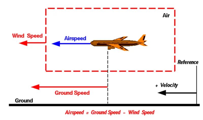
Ground Speed: Ground speed is the horizontal speed of an aircraft relative to the surface of Earth. Ground speed can be determined by the vector sum of the aircraft's true airspeed (TAS) and the current wind speed and direction; there are two conditions in ground speed which is Headwind conditions and Tailwind conditions.
- Headwind conditions - Ground speed (GS) = True Air Speed (TAS) - Wind Component
- Tailwind conditions - Ground speed (GS) = True Air Speed (TAS) + Wind Component
A headwind subtracts from the ground speed, while a tailwind adds to it. Winds at other angles to the heading will have components of either headwind or tailwind as well as a crosswind component.
Air Speed: The important quantity in the generation of lift is the relative velocity between the object and the air, which is called the airspeed. Airspeed cannot be directly measured from a ground position, but must be computed from the ground speed and the wind speed. Airspeed is the vector difference between the ground speed and the wind speed.
Airspeed = Ground Speed - Wind Speed
On a perfectly still day, the airspeed is equal to the ground speed. But if the wind is blowing in the same direction that the aircraft is moving, the airspeed will be less than the ground speed.
Example
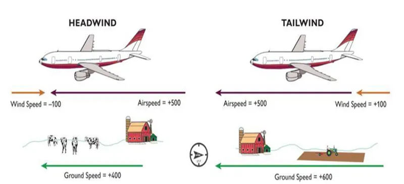
To give you an actual example, imagine an aircraft that cruises at an airspeed of 500 miles per hour that has to cover a ground distance of 2,000 miles.
If there is no wind at all, then both the aircraft’s airspeed and ground speed would be the same 500 miles per hour, and the aircraft would reach its destination in four hours.
If there was a 100 miles per hour headwind – wind blowing against the aircraft’s direction of travel – the aircraft would still be traveling at an airspeed of 500 miles per hour. However, its ground speed would be just 400 miles per hour (100 miles per hour slower than its airspeed). And as such, it would take the aircraft five hours to reach its destinations.
Finally, if there was a 100 miles per hour tailwind – wind blowing in the same direction as the aircraft’s travel – the aircraft would still be traveling at an airspeed of 500 miles per hour, but its ground speed would be 100 miles faster.
And, at 600 miles an hour, the aircraft would reach its destination in just three hours and twenty minutes.
Q3. Why is it not recommended to use aircraft engine power to move it on the ground at Airport?
Ans 3:
Reason Why is it not recommended to use aircraft engine power to move it on the ground at Airport is that, Engine power is used all the time to move aircraft on the ground. The forward movement of an aircraft, usually with engines off, using the power of a specialized ground vehicle attached to or supporting the nose landing gear and this process is called towing. It may occur for the movement of both in service and out of service aircraft.
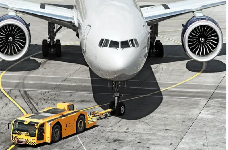
Airplanes get towed when the thrust of their engines creates a significant hazard to the immediate area surrounding them. Planes also get towed for maintenance purposes so pilots are not required to move the aircraft as airplane mechanics are trained in the use of the aircraft brakes while towing. The small vehicle is needed to push the larger commercial airplanes backwards away from the terminal building, because even if a plane can reverse its thrust, it’s not always safe to hit the buildings with that reverse thrust.
Aircraft are designed to fly. When they’re going to spend more than 15 hours in the air, they need to perform as efficiently as possible so doing towing we can save fuel.
Q 4. How an aircraft is pushed to runway when its ready to take off?
Ans 4: Aircraft is pushed to runway when its ready to take-off from parking areas to runway by towing procedure.
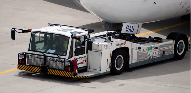
Ready for take-off in ten steps…
- The pilot parks the aircraft in exactly the right place. Usually with the help of an automatic system, but occasionally guided by a marshaller waving two paddles or wands. Dozens of handling personnel are already standing by to perform a whole range of tasks simultaneously.
- As soon as the aircraft is stationary and the engines are switched off, the first priority is to disembark the passengers as quickly as possible. The apron handler places chocks in front of the wheels and connects the ground power. Meanwhile, the passenger bridge manoeuvres up to the door and a belt loader rolls up to the cargo hold. Luggage is unloaded and transferred to the terminal on baggage carts.
- Refuelling begins, usually from a hydrant at the stand. A hose is attached to this from a special vehicle called a dispenser, with the other side connected to the fuel tank in the wing. Read more about refuelling here.
- Now it is time to service the aircraft. The caterer loads new meals and takes away the food waste and used cutlery and crockery. Other activities include draining the lavatories, replacing the headrest covers, removing rubbish and distributing fresh blankets and in-flight magazine.
- A specialist team – or sometimes the crew themselves – cleans the cabin so that the new passengers board a pristine aircraft.
- Meanwhile, specialists from the airline conduct a technical check to make sure that the engines, wings, control surfaces, landing gear, instruments, doors and other equipment are in full working order.
- The aircraft is now ready for baggage to be loaded for the next flight. This is a quick process, on average taking only 10-15 minutes. A little later the passengers start boarding. As soon as they are all in their seats, the door is closed and the pilot informs air-traffic control that the flight is ready for departure.
- The apron handler removes the chocks. A so-called pushback truck reverses the aircraft into taxiing position, pushing it with a towbar attached to the nose-wheel strut. Or, in the most modern versions, by actually lifting the wheel. That speeds up coupling and decoupling.
- The aircraft taxis to the runway to depart at the agreed time.
- The pilot waits for permission to take off from air-traffic control. This is possible once the departure route is clear. As soon as the go-ahead is received, the plane takes to the air at full power.
Q5. Learn about take off power, tyre design, rolling resistance, tyre pressure, brake forces when landing.
Ans 5:
A)Take off power:
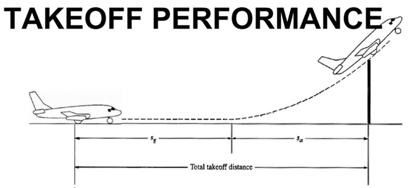
The amount of power that an engine is allowed to produce for a limited period of time for takeoff. The use of takeoff power isusually limited to 5 min for reciprocating engines and up to 2½ min for gas turbine engines. This may not always be the case. Specifically, with respect to reciprocating engines, it is the brake horsepower developed under standard, sea-level conditions and under the maximum conditions of the crankshaft rotational speed and the engine manifold pressure approved for the normal takeoff. It is limited in continuous use to the period of time shown in the approved engine specifications. With respect to gas turbine engines, it is the thrust developed under static conditions at a specified altitude and atmospheric conditions of the rotor shaft rotational speed and gas temperature approved for the normal takeoff. It is limited in continuous use to the period of time shown in the approved engine specifications.
Take off performance can be predicted using a simple measure of the acceleration of the aircraft along the runway based on force equilibrium.
The forces involved will be,
T – Thrust of propulsion system pushing aircraft along runway.
D – Aerodynamic Drag of vehicle resisting the aircraft motion.
F – Rolling resistance friction due to the contact of wheels or skids on the ground.
During take-off run the imbalance in these forces will produce an acceleration along the runway.
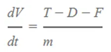
where dV/dt is the acceleration along the runway and m is the mass of the vehicle.
- B) Tyre design:
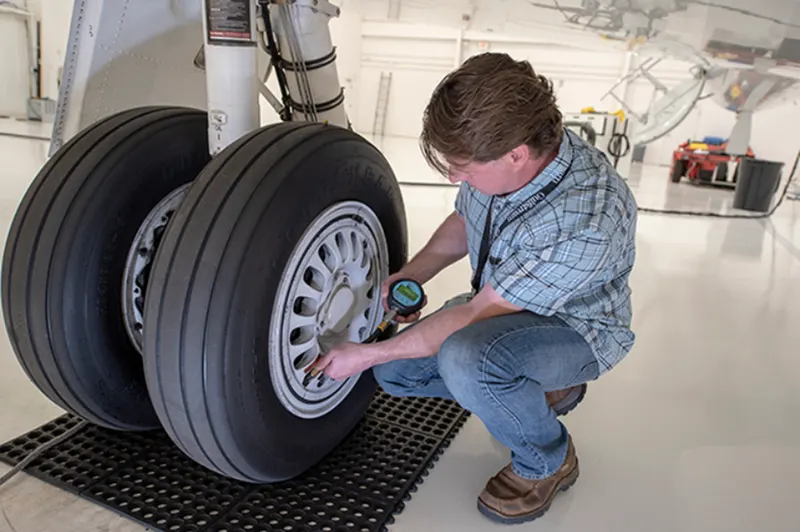
When it comes to safety, tyres are one of the most important components of aircraft. They help to absorb the shock of landing and provide cushioning. It also provides the necessary traction for braking and stopping of an aircraft.
An aircraft tyre is designed to withstand extremely heavy loads while landing, take off, taxing, and parking. The number of wheels required for aircraft increases with the weight of the aircraft, as the weight of the aeroplane needs to be distributed more evenly.
Design and construction of aircraft tyre
Carcass plies are used to form the tire. They are sometimes called casing plies. An aircraft tyre is constructed for the purpose it serves.
- They support the weight of an aircraft while it is on the ground.
- It also provides the necessary traction for braking and stopping of an aeroplane.
- Tyre also helps to absorb the shock of landing and provide cushioning the roughness of takeoff, roll-out, and taxi operations.
Unlike an automobile or truck tyre, it does not have to carry a load for a long period of continuous operation. However, an aircraft tyre absorbs the high impact loads of landing, and also it’s operating at high speeds for a short time when required.
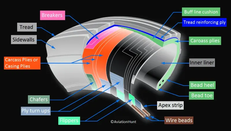
Let’s go through some technical aspects of the tyre.
Retreading – Retreading is methods of restoring a worn tyre by renewing the tread area or by renewing the tread area plus one or both sidewalls. Repairs are included in the tyre retreading process.
Load Rating – Load rating is the maximum permissible load at a specified inflation pressure.
Ply Rating – Ply Rating is used to identify the maximum recommended load rating and inflation pressure for a specified tyre. It is an index of tyre strength.
Speed Rating – The speed rating is the maximum takeoff speed to which the tyre has been tested.
Skid Depth – Skid depth is the distance between the tread surface and the deepest groove as measured in the mould.
Aircraft tyres must have an approved speed and load rating and have sufficient clearance when retracted through landing gear to allow for tyre growth. Tyre growth is the increase in the size of the tyre due to centrifugal forces at high speed.
- C) Rolling resistance: Rolling resistance, sometimes called rolling friction or rolling drag, is the force resisting the motionwhen a body (such as a ball, tire, or wheel) rolls on a surface.
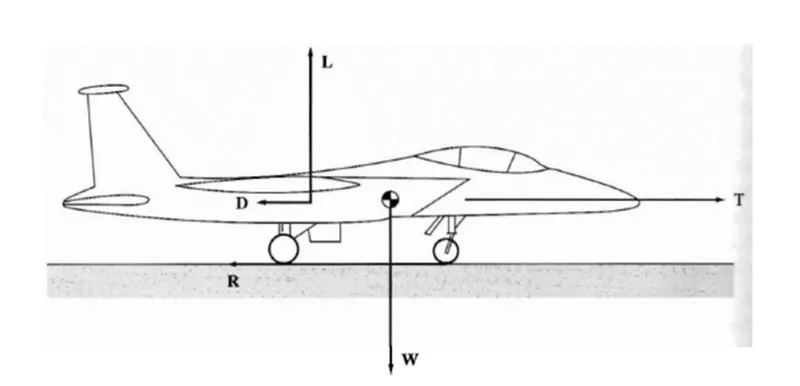
The friction between aircraft and runway will be proportional to the normal force exerted by the aircraft on the runway.
F=μ(W−L)
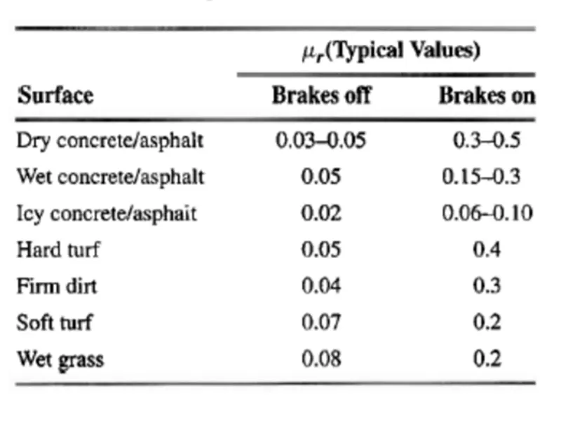
The normal force will be the difference between Weight of aircraft and Lift, the friction coefficient will be typically of a magnitude of 0.02 for a standard tarmac runway.
Typical Value of μrr for aircraft
- D) Tyre pressure:
Aircraft tires generally operate at high pressures, up to 200 psi (14 bar; 1,400 kPa) for airliners, and even higher for business jets. The main landing gear on the Concorde was typically inflated to 232 psi (16.0 bar), whilst its tail bumper gear tires were as high as 294 psi (20.3 bar).
For example
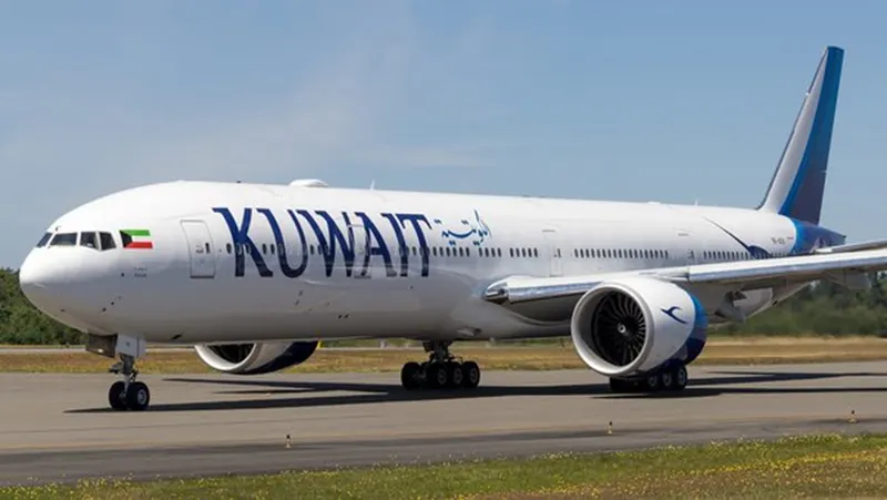
A Boeing 777 fully loaded weighs around 700,000 pounds and has fourteen tires:Therefore, if each of those tires is reacting roughly the same force, then that is 50,000 pounds per tire. The tyre pressure 200psi. Therefore there should be 250 square inches of surface contact area for each tire with the ground (250 * 200 = 50,000) and 250 in area would be 25 inches by 10 or more likely 16 x 16 inches.
- E) Brake forces:
Airplanes rely on a braking system to safely land on runways. At cruising altitude, most commercial airplanes fly at a speed of roughly 500 to 600 mph. When landing, however, they must reduce their speed. A typical 747, for instance, has a landing speed of about 160 to 170 mph. And upon touching the runway, airplanes must quickly brake until they come to a complete stop.
Wind sopilers :Many airplanes use wing spoilers to assist with braking when landing. Not to be confused with ailerons, spoilers are extendable flaps on the ends of an airplane’s wings. Pilots can raise the spoilers to decelerate the airplane as it approaches the runway. And even while on the runway, pilots will typically leave the wing spoilers raised. Raised wing spoilers create drag, which essentially slows down the airplane so that it’s able to brake more quickly.
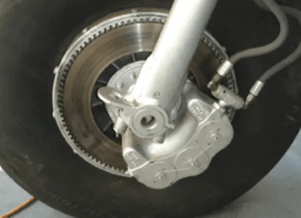
Disc Brakes : In addition to wing spoilers, airplanes use disc brakes. Airplane disc brakes are similar to the braking system in automobiles. They consist of a pair of calipers that, when engaged, squeeze pads against the rotors of an airplane’s landing gear.
Disc brakes are designed to remain static at all times. In other words, they don’t rotate with the wheels of an airplane’s landing gear. As the wheels turn, the disc brakes will remain static and stationary. They are a vital component of an airplane’s braking system because they are designed to apply pressure to the airplane’s wheels. Disc brakes will squeeze the wheels, thereby slowing down the speed at which they spin. In turn, this reduces the speed of the airplane so that it can come to a complete stop on the runway.
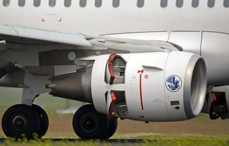
Reverse Thrust : Finally, many jet airplanes use reverse thrust to assist with braking during landings. Reverse thrust is a feature in jet engine airplanes that, as the name suggests, involves the reversal of the engines’ thrust. When flying, the thrust is projected out the rear of an airplane’s engines. When landing, however, pilots may use the reverse thrust feature. Reverse thrust changes the direction of the engines’ thrust. Rather than projecting out the rear, the thrust will be projected out the front. This reversal of thrust provides deceleration that allows airplanes to slow down more quickly when landing.
Part B:
Q 6. A. With necessary assumptions, calculate the force and power required to push / pull an aircraft by a towing vehicle.
Ans 6:
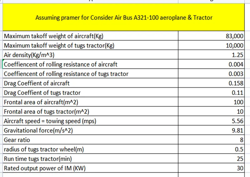
Assumption
Consider Air Bus A321-100
Maximum takoff weight of aircraft = 83,000Kg
Maximum takoff weight of tugs tractor = 10,000Kg
Air density = 1.25Kg/m^3
Coeffiencent of rolling resistance of aircraft = 0.004
Coeffiencent of rolling resistance of tugs tractor = 0.003
Drag Coeffient of aircraft = 0.158
Drag Coeffient of tugs tractor = 0.11
Frontal area of aircraft = 100m^2
Frontal area of tugs tractor = 10m^2
Aircraft speed = towing speed = 5.56mps i.e. 20kmph
Gravitational force = 9.81
- A) Rolling resistance force for an aircraft
Frr = μrr * m * g
= 0.004 * 83000 * 9.81
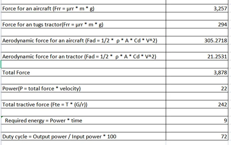
= 3256.92N
- B) Aerodynamic force for an aircraft
Fad = 1/2 * ρ * A * Cd * V^2
= 1/2 * 1.25 * 100 * 0.158 * 5.56^2
= 305.27N
- C) Rolling resistance force for an tugs tractor
Frr = μrr * m * g
= 0.003 * 10000 * 9.81
= 294.3N
- D) Aerodynamic force for an tugs tractor
Fad = 1/2 * ρ * A * Cd * V^2
= 1/2 * 1.25 * 10 * 0.11 * 5.56^2
= 21.25N
Total Force required to push / pull an aircraft by a towing vehicle = Rolling resistance force for an aircraft + Aerodynamic force for an aircraft + Rolling resistance force for an tugs tractor + Aerodynamic force for an tugs tractor
= 3256.92 + 305.27 + 294.3 + 21.25
= 3877.74N
Total power required to push / pull an aircraft by a towing vehicle = Total Force required to push / pull an aircraft by a towing vehicle = total force * velocity
= 3877.74 * 5.56
= 21560.23W
= 21.56KW
- Develop the model for the calculated force and power using Simulink.
Ans :
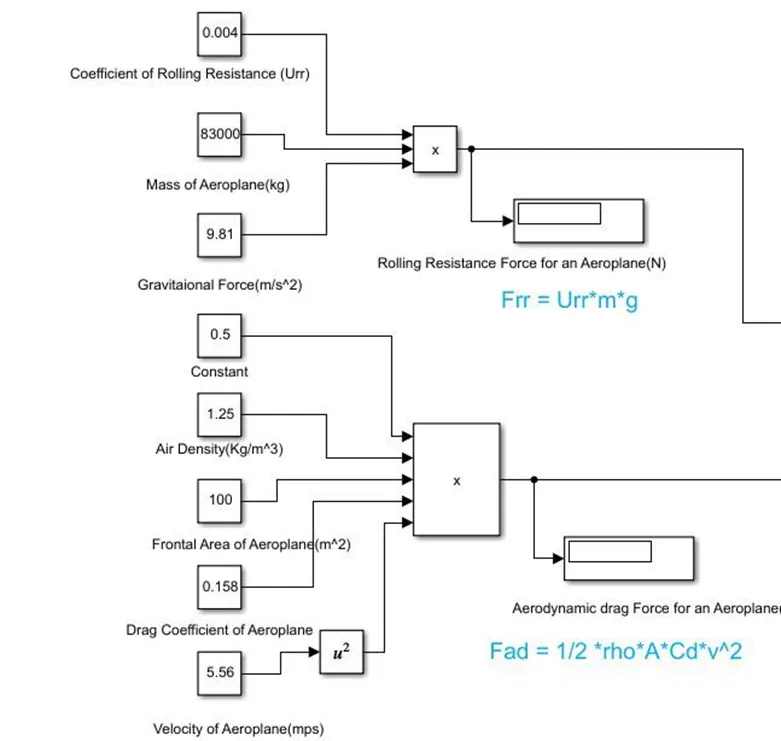
Calculation done using matlab simulink model to find out power and force
In this model there are two forces which is
- Force on Aeroplane
- Force on tugs tractor
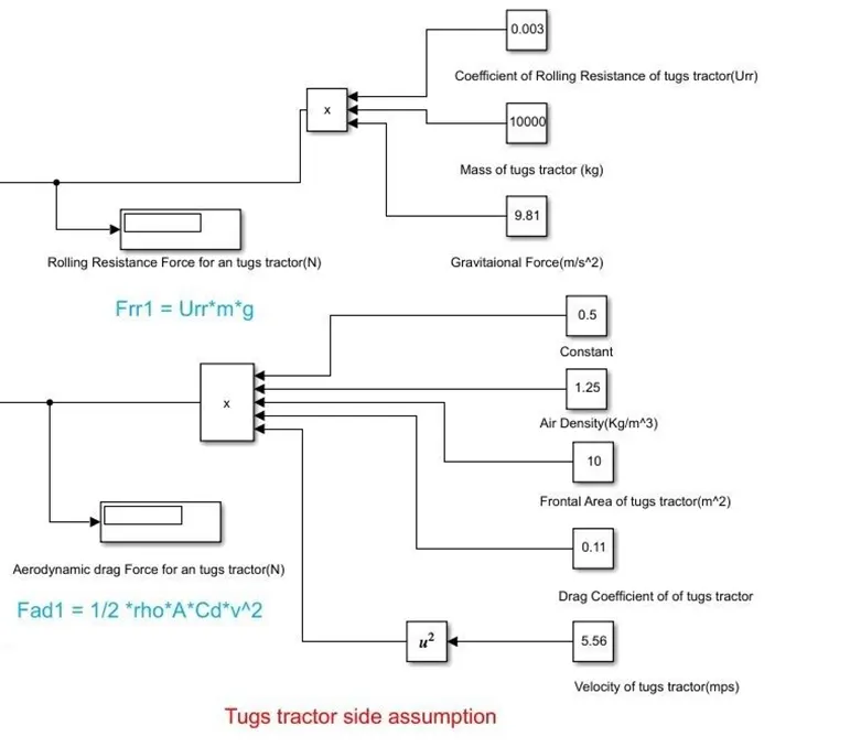
Complete model to calculation of power and torque
Q7. A. Design an electric powertrain with type of motor, it’s power rating, and energy requirement to fulfill aircraft towing application in Simulink. Estimate the duty cycle range to control the aircraft speed from zero to highest. Make all required assumptions. Prepare a table of assumed parameters. Draw a block diagram of powertrain.
Ans 7:
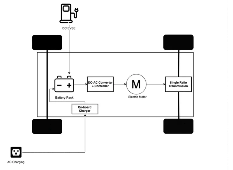
Refer Q.6 (A) ans and after that
As we konwn that ,
Fte = T * (G/r)
where,
Fte = Total tractive force
T = Torque req. for wheel
G = Gear ratio (assume 8)
r = radius of wheel (assume 0.5m)
Fte = T * (G/r)
Fte = T * (G/r)
3877.74 = T * (8/0.5)
T = 242.35Nm
This torque 242.35Nm is required by tugs tractor to pull aeroplane
Total power required to push / pull an aircraft by a towing vehicle = 21.56KW
Required time to pull aeroplane from parking areas to runways consider as 25min
So,
Required energy = Power * time
Required energy = 21.56* (25/60)
Required energy = 8.98Kwh
Induction motor rating
No. Definition Data Unit Remarks
1 Product TEFC, 3-phase, squirrel cage induction motor
2 Product code 3GBA 202 410-ADCIN Calc. ref. 3GZH021020-3
3 Type/Frame M2BAX 200MLA 4
4 Mounting IM1001, B3(foot)
5 Rated output PN 30 kW
6 Service factor 1
7 Rated voltage UN 415 VD +10, -10 %
8 Rated frequency fN 50 Hz +5, -5 %
9 Rated speed nN 1474 r/min
10 Rated current IN 55.5 A
11 Starting current Is/IN 7
12 Maximum torque Tmax/TN 3.5
Duty cycle calculation
The motor output power is the input power of the towing vehicle so to obtain maximum speed, the duty cycle need to be calculated as,
Duty cycle = Output power / Input power * 100
Duty cycle = 21.56 / 30 * 100
Duty cycle = 71.86
duty cycle range to control the aircraft speed from 0 to 71.86%
- Also, Design the parameters in excel sheet.
Conclusion
Hence, we understand deep studies about aircraft and calculation are performed to find force and power required to push/pull an aircraft by a towing vehicle. Also, we calculate energy, duty cycle requirement for aircraft application.