Project-1: Powertrain for aircraft in runways
AIM:- Powertrain for aircraft in runways
1. Search and list out the total weight of various types of aircrafts. 2. Is there any difference between ground speed and air speed?
3. Why is it not recommended to use aircraft engine power to move it on the ground at Airport?
4. How an aircraft is pushed to runway when it's ready to take off?
5. Learn about take-off power, tyre design, rolling resistance, tyre pressure, brake forces when landing.
6. With necessary assumptions, calculate the force and power required to push / pull an aircraft by a towing vehicle.
7. Design an electric powertrain with type of motor, its power rating, and energy requirement to fulfil aircraft towing application. Estimate the duty cycle range to control the aircraft speed from zero to highest. Make all required assumptions. Prepare a table of assumed parameters. Draw a block diagram
An aircraft's gross weight is limited by several weight restrictions in order to avoid overloading its structure or to avoid unacceptable performance or handling qualities while in operation. Aircraft gross weight limits are established during an aircraft's design and certification period and are laid down in the aircraft's type certificate and manufacturer specification documents. The absolute maximum weight capabilities of a given aircraft are referred to as the structural weight limits. The structural weight limits are based on aircraft maximum structural capability and define the envelope for the CG charts (both maximum weight and CG limits). An aircraft's structural weight capability is typically a function of when the aircraft was manufactured, and in some cases, old aircraft can have their structural weight capability increased by structural modifications.
Type MTOW [kg] MLW (tons] ICAO category FAA category
Antonov An-225 640,000 591.7 Heavy Super
Scaled Composites Model 351 Strotolaunch 589,670 Heavy Super
Airbus A380-800[1][2][3] 575,000 394 Super Super
Boeing 747-BF 447,700 346.001 Heavy Heavy
Boeing 747-8 443.613 306.175 Heavy Heavy
Boeing 747-400ER 412,770 205.742 Heavy Heavy
Antonov An-124-100M 405,000 330 Heavy Heavy
Boeing 747-400 369,900 295.742 Heavy Heavy
Lockheed C-5 Galaxy[4][5][6] 381,000 288.417 Heavy Heavy
Boeing 747-200[7] 37,840 285.700 Heavy Heavy
Boeing 747-300[7] 377,840 260.320 Heavy Heavy
Airbus A340-500[8] 371,950 240 Heavy Heavy
Airbus A340-600[8] 367,400 256 Heavy Heavy
Boeing 777F 347,800 260,816 Heavy Heavy
Boeing 777-300ER 351,800 251,29 Heavy Heavy
Boeing 777-200LR 347,450 223.168 Heavy Heavy
Boeing 747-100[7] 340,200 265.300 Heavy Heavy
Airbus A350-1000 308,000 233.5 Heavy Heavy
Boeing 777-300 299,370 237.683 Heavy Heavy
Boeing 777-200ER 297,550 213.00 Heav Heavy
Here, MTOW-=Maximum toke-off weight, MLW = Maximum landing weight, TOR= Take-off run (5L SA 15%, MTOW), LR= Landing run(SL,ISA+15Degree,MLW)
MANUFACTURER'S DESIGN WEIGHT LIMITATION
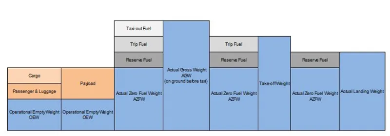
The maximum allowable weight for an aircraft is determined by design considerations by the aircrafts manufacturer, However, the maximum operational weight may be less than the maximum aliowable weight due to such considerations as high-density altitude or high-drag field conditions caused by wet grass or water on the runway. The maximum operational weight may also be limited by the departure or arrival airport's runway length. The structural weight limits are based on aircraft maximum structural capability and define the envelope for the CG charts. Aircraft structural weight capability is established during aircraft design and certification
Maximum design taxi weight (MDTW)
The maximum design taxi weight (also known as the maximum design ramp weight (MDRW)) is the maximum weight certificated for aircraft maneuvering on the ground (taxiing or towing) as limited by aircraft strength and airworthiness requirements.
Maximum design takeoff weight (MDTOW)
Is the maximum certificated design weight when the brakes are released for takeoff and is the greatest weight for which compliance with the relevant structural and engineering requirements has been demonstrated by the manufacturer.
Maximum design landing weight (MDLW)
The maximum certificated design weight at which the aircraft meets the appropriate landing certification requirements. It generally depends on the landing gear strength or the landing impact loads on certain parts of th wing structure. The MDLW must not exceed the MDTOW. The maximum landing weight is typically designed for 10 F per second (600 feet per minute) sink rate at touch down with no structural damage.
Authorised weight limits
Aircraft authorized gross weight limits (also referred to as certified weight limits) are laid down in the aircraft flight manuals (AFM) and/or associated certificate of airworthiness (C of A). The authorized or permitted limits may be equal to or lower than the structural design weight limits. The authorized weight limits that can legally be used by an operator or airline are those listed in the AFM and the weight and balance manual. The authorised (or certified) weight limits are chosen by the customer/airline and the are referred to as the "purchased weights. An operator may purchase a certified weight below the maximum design weights because many of the airport operating fees are based on the aircraft AFM maximum allowable weight values. An aircraft purchase price is typically, a function of the certified weight purchased.
Maximum weights established, for each aircraft, by design and certification must not be exceeded during aircraft operation (ramp or taxying, takeoff, en-route flight, approach and landing) and during aircraft loading (zero fuel conditions, center of gravity position, and weight distribution). Weights could be restricted on some type aircraft depending on the aircraft handling requirements: for example aerobatic aircraft, where certain aerobatic manoeuvres can only be executed with a limited gross weight.
Maximum taxi weight (MTW):
The maximum taxi weight (MTW) (also known as the maximum ramp weight (MRW) is the maximum weight authorized for maneuvering (taxiing or towing) an aircraft on the ground as limited by aircraft strength and airworthiness requirements. It includes the weight of taxi and run-up fuel for the engines and the APU. It is greater than the maximum takeoff weight due to the fuel that will be burned during the taxi and runup operations. The difference between the maximum taxi/ramp weight and the maximum take-off weight (maximum taxi fuel allowance) depends on the size of the aircraft, the number of engines, APU operation, and engines/APU fuel consumption, and is typically assumed for 10 to 15 minutes allowance of taxi and run-up operations.
Maximum takeoff weight (MTOW):
The maximum takeoff weight (also known as the maximum brake-release weight) is the maximum weight authorised at brake release for takeaff, or at the start of the takeoff roll. The maximum takeoff weight is always less than the maximum taxi/ramp weight to allow for fuel burned during taxi by the engines and the APU. In operation, the maximum weight for takeoff may be limited to values less than the maximum takeoff weight due to aircraft performance, environmental conditions, airfield characteristics (takeoff field length, altitude), maximum tire speed and brake energy, obstacle clearances, and/or en route and landing weight requirements.
Maximum landing weight (MLW):
The maximum weight authoriser for normal landing of an aircraft. The MLW must not exceed the MTOW. The operation landing weight may be limited to a weight lower than the Maximum landing Weight by the most restrictive
EFFECTS OF WEIGHT
Some of the problems caused by overloading on aircraft are
- The aircraft wil need a higher takeoff speed, which results in a longer toksoff run
- Both the rate and angle of climb will be reduced
- The service ceiling will be lowered
- The cruising speed will be reduced.
- The cruising range will be shortened.
- Maneuverability will be decreased.
- A longer landing roll will be required because the landing speed will be higher
- Excessive loads will be imposed on the structure, especially the landing gear.
DEFINITIONS
AIRCRAFT GROSSWEIGHT
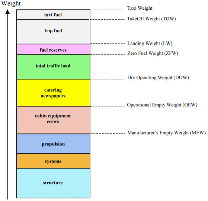
The aircraft gross weight is the total aircraft weight at any moment during the flight or ground operation
The aircraft gross weight decreases during flight due to fuel and oil consumption. The aircraft gross weight may also vary during flight due to payload dropping or in-flight refueling
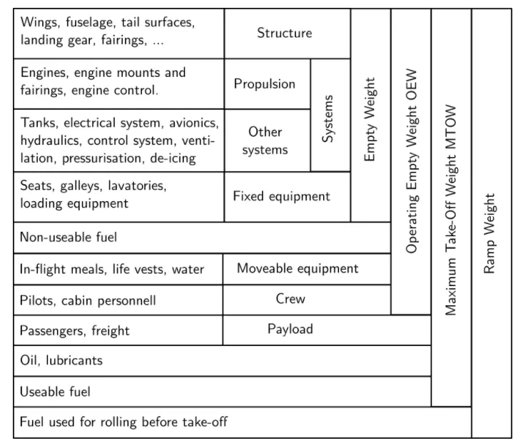
MANUFACTURER'S EMPTY WEIGHT (MEW)
Let's start with the aircraft itself. An aircraft "as is" includes
- Airframe structure with all moving mechanical parts (fuselage, wings, flaps, gear, rudder, nacelle)
- Power generation system (APU, main engines, power plant.)
- Systems (electrical hydraulics, pneumatic, fuel flow system, instrument, navigation, air conditioning, anti-ice fixed furnishing)
- Fixed equipment and services considered an integral part of the aircraft
- Fixed ballast
- Closed system fluids
- Unused fuel only for small aircraft
All these items above form the Manufacturer's Empty Weight (MEW).
This weight does not include:
- Fuel,Oil, potable water
- Payload (Cargo, passenger, luggage) Removable equipment
- Customer specific installations or operator items
Difference between wind speed and ground speed
Wind Speed:
for a reference point picked on the ground, the air moves relative to the reference point of the wind speedt Notice that the wind speed is a vector quantity and has both a magnitude and a direction Direction is important. A 20 mph wind from the weet is different from a 20 mph wind from the east. The wind hos components in all three primary directions (north-south, ost west, and up-down), in this figure, we are considering only velocities along the aircrafts fight path A positive velocity is defined to be in the direction of the aircrafts motion We are neglecting cross winds which occur perpendicular to the fight path but parallel to the ground, and updrotts and downdrafts, which occur perpendicular to the ground
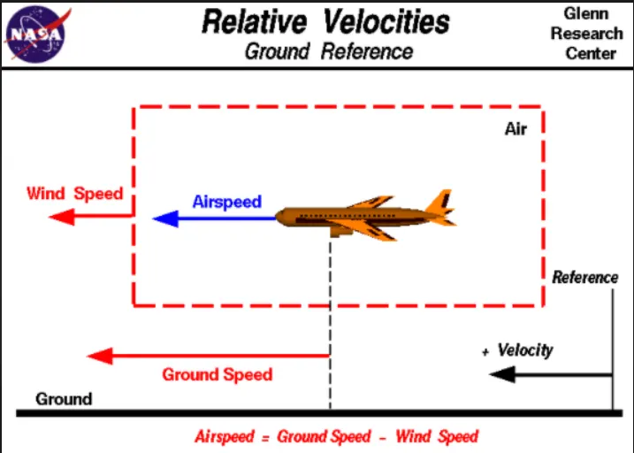
Ground Speed
For a reference point picked on the ground, the aircraft moves relative to the reference point at the ground speed Ground speed is also a vector quantity so a comparison of the ground speed to the wind speed must be done according to rules for vector comparisons
Airspeed
The important quantity in the generation of lift is the relative velocity between the object and the air, which is called the airspeed. Airspeed cannot be directly measured from a ground position, but must be computed from the ground speed and the wind speed. Airspeed is the vector difference between the ground speed and the wind speed.
Air speed= Ground Speed -Wind Speed
conclusion:
Yes, there is a difference between ground speed and air speed. Ground speed is how fast an airplane's shadow would move across the land. If there's a strong wind pushing an aircraft, that's reflected in the ground speed. Airspeed, in contrast, is how fast an airplane is really flying strictly under its own power, which is calculated by subtracting the wind speed from the ground speed. On a perfectly still day, the airspeed is equal to the ground speed. But if the wind is blowing in the same direction that the aircraft is moving, the airspeed will be less than the ground speed
3. Why is it not recommended to use aircraft engine power to move it on the ground at Airport?
Ans:-Movement of large aircraft about the airport, flight line, and hangar is usually accomplished by towing with a tow tractor (sometimes called a tug'). In the case of small aircraft, some moving is accomplished by hand pushing on the correct areas of the aircraft. Aircraft may also be taxied about the fight line but usually only by certain qualified personnel
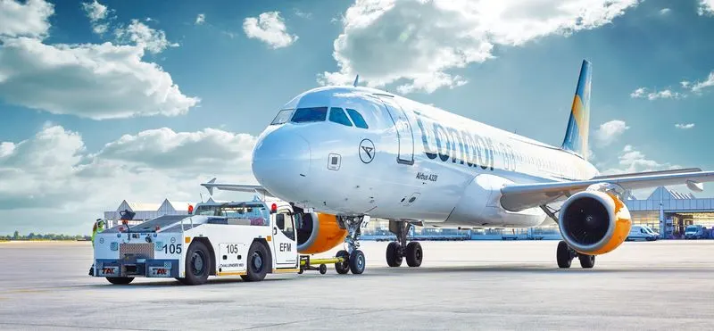
Although many aircraft are capable of moving themselves backwards on the ground using reverse thrust (a procedure referred to as a power back). the resulting jet blast or prop wash might cause damage to the terminal building or equipment Engines close to the ground may also blow sand and debris forward and then suck them into the engine, causing damage to the engine, A pushback is therefore the preferred method to move the aircraft away from the gate
Following are the reasons to use Towing vehicle instead of aircraft engine
- The jet blast from the engines can damage the terminal building and nearby equipment.
- It can even throw away people standing nearby Engines can blow sand and debris. Engines can suck in sand and debris which can cause serious damage to the engine
- It is easier for the truck driver to see the surroundings better than the pilot sitting in the cockpit with limited windows
- The pushbock truck driver knows the airport better than the pilot. The plane engines are very loud. This noise.can add up substantially when multiple planes are moving around the airport. It won't be a pleasant experience for people sitting inside the terminal as most people don't even like the sound of powerful motor bikes
- It saves fuel virgin Atlantic had proposed a new system in which the pushback trucks will push the plane all the way to the runway to save fuel and reduce impact on nearby environment.
4. How an aircraft is pushed to runway when its ready to take off?
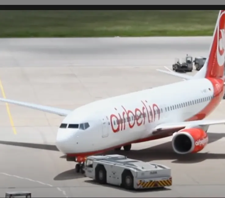
Ans:- The aircraft is pushed to runway using TAXING
Toxing (rarely spelled toxying) is the movement of an aircraft on the ground, under its own power, in contrast to towing or push-bock where the aircraft is moved by a tug. The aircraft usually moves on wheels, but the term also includes aircraft with skis or floats (for water-based travel)
An airplane uses taxtways to tail from one place on an airport to another for womple, when moving from a hongar to the runway. The term 'taxing is not used for the accelerating run along a runway prior to tokeoff, or the decelerating run immediately after landing, which are called the takeoff roll and landing rollout, respectively.
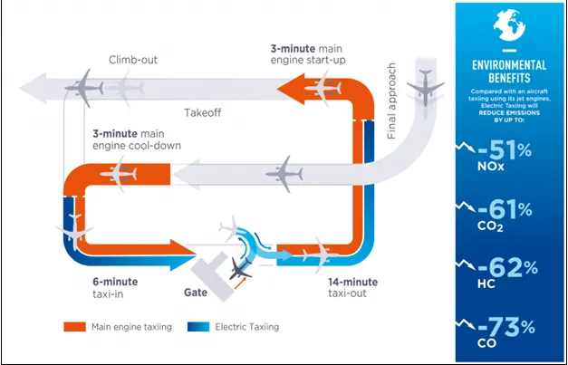
Electric Toxing
with the electric taxing system on aircraft would be more autonomous and able to reverse and departats stond more quickly, without relying on ground services and infrastructure. This solution would help improve traffic flows in the apron and at gotes improve tight punctuality and gain precious minutes on the ground, thereby contributing to maximizing the capacity of airports.
Control During Towing
Steering is achieved by turning a nose wheet ar tail wheet/rudder the plict controls the direction traveled with their feer Larger jet aircratt have a the wheel on the left side of the cockpit that octs as u steering wheel ollowing the nosarwheel to be turned hydraulically, Braking is controlled by differential toe. heel brakes. Not all aircraft have steetable wheels and in some cases steening is solely by means of differential braking (all vans aircraft for instance) or solely by means of the rudder (including of footplates)
5. Learn about take off power, tyre design, rolling resistance, tyre pressure, brake forces when landing.
Ans:-
- Take off power:
Takeoff is the phase of flight in which an aerospace vehicle leaves the ground and becomes airborne. For aircraft traveling vertically, this is known as liftoff. For aircraft that take off horizontally, this usually involves starting with a transition from moving along the ground on a runway. For light aircraft, usually full power is used during takeoff. Large transport category (airliner) aircraft may use a reduced power for takeoff, where less than full power is applied in order to prolong engine life, reduce maintenance costs and reduce noise emissions.
After toxiing onto the runway, the airplane should be carefully aligned with the intended takeoff direction, and the nose wheel positioned straight or centered. After releasing the brakes, the throttle should be advanced smoothly and continuously to tokeoff power. An abrupt application of power may cause the airplane to yaw sharply to the left because of the torque effects of the engine and propeller. This will be most apparent in high horsepower engines.
As the airplane starts to roll forward the pilot should assure both feet are on the rudder pedals so that the toes or ballsof the feet are on the rudder portions, not on the broke portions of Acceleration of the aircraft anong the runway Takeoff performance can be predicted by using a simple measure based on force equilibrium
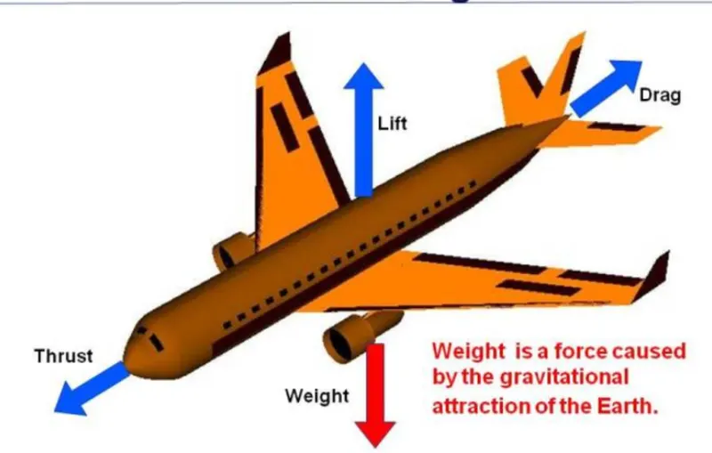
The forces involved will be
T-Thrust of propulsion system pushing aircraft along runway
D-Aerodynamic Drag of vehicle resisting the aircraft motion
F-Rolling resistance friction due to the contact of wheels or skids on the ground.
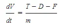
During take-off run the imbalance in these forces will produce an acceleration along the runway where dv/dt is the acceleration along the runway and m is the mass of the vehicle
- Rolling Resistance:
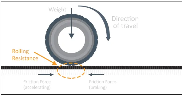
Rolling resistance, sometimes called rolling friction or rolling drog, is the force resisting the motion when a body (such as a ball, tire, or wheel) rolls on a surface. It is mainly caused by non-alastieffects; that is not all the energy needed for deformation (or movement) of the wheel roodbed, etc, is recovered when the pressure is removed. Two forms of this are hysteresis losses (see below), and permanent (plastic) deformation of the object or the surface (eg. sol) Note that the slippage between the wheel and the surface also results in energy dissipation. Although some
researchers have included this term in rolling resistance, some suggest that this dissipation term should be treated separately from rolling resistance because it is due to the applied torque to the wheel and the resultant slip between the wheel and ground, which is called slip loss or slip resistance in addition, only the so-called slip resistance involves friction, therefore the name 'rolling friction is to an extent a misnomer.
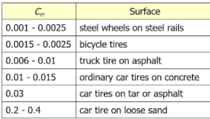
The rolling resistance coefficient is defined by the following equation:

where
F=Rolling resistance force

N=Normal force, the force perpendicular to the surface on which the wheel is rolling
- Tyre pressure:-
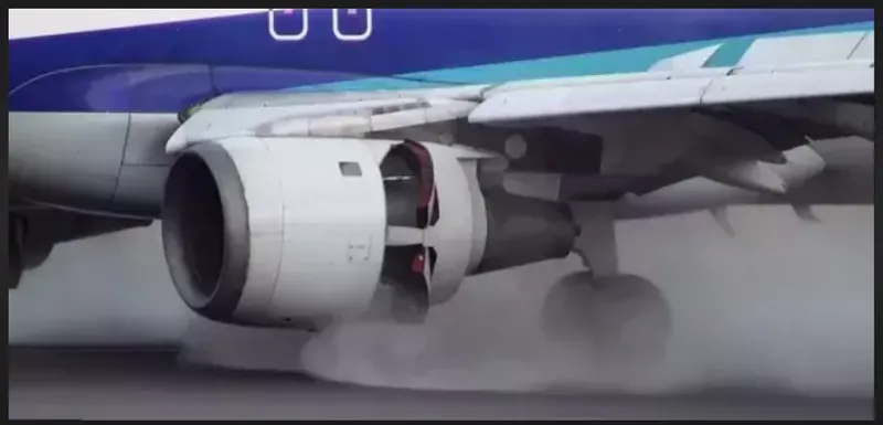
The pressure generally is very high in an aircraft tire to reduce the rolling resistance and to withstand the weight. Usually it will be around 200 to 300 psi of pressure and they change based on the type of the aircraft. Tests of airliner aircraft tyres have shown that they are able to sustain pressures of maximum 800 psi. Aircraft tyres are usually inflated with nitrogen to minimize expansion and contraction from extreme changes in ambient temperature and pressure experienced during flight.
The typical airliner tire can handle a 38-ton load. It can meet the ground 500 times before needing a re-tread, a refresh it can take on seven times in its life. Aircraft tires generally operate at high pressures, up to 200 psi (14 bar; 1,400 kPa), for airliners, and even higher for business jets. The main landing gear on the Concorde was typically inflated to 232 psi (16.0 bar), whilst its tail bumper gear tires were as high as 294 psi (20.3 bar).
- Brake forces:-
In aircraft types, the brake units are powered by the hydraulics system. An electrical signal is sent from the flight deck to hydraulic actuators near the main landing gear. Here, hydraulic fluid 3,000 pound per square inch is used to force the brake unit against the wheel, thus slowing it down.
- Tyre Design:-
An aircraft tyre is constructed for the purpose it serves.
1.They support the weight of an aircraft while it is on the ground
2. It also provides the necessory traction for braking and stopping of an oero plane .
3.They also helps to absorb the shock of landing and provide cushioning the roughness of tokeoff, roll-out, and taxi operations.
Unlike an automobile or truck tire, it does not have to carry a load for a long period of continuous operation. Howeveran aircraft tyre absorbs the high impact loads of landing, and also it's operating at high speeds for a short time when required.
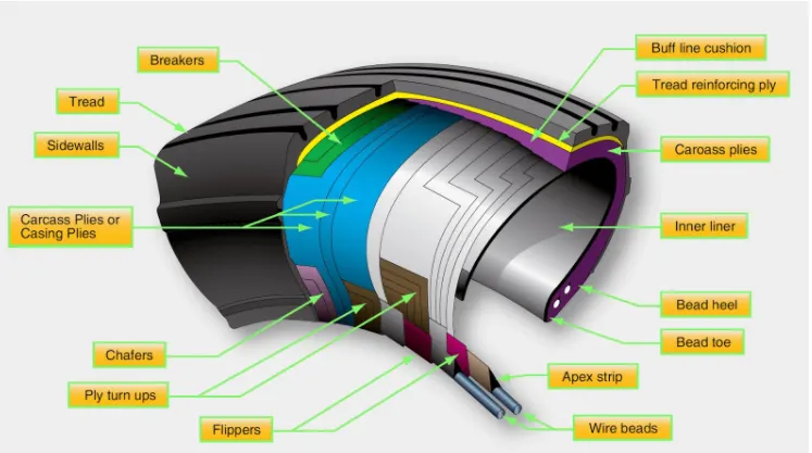
Retreading-Retreading is methods of restoring a worn tyre by renewing the tread area or by renewing the tread area plus one or both sidewalls. Repairs are included in the tyre retreading process
Load Rating - Load rating is the maximum permissible tood at a specified inflation pressure.
Ply Rating Ply Rating is used to identify the maximurn recommended lood rating and inflation pressure for a specified tyre, it is an index of tyre strengt
Speed Rating The speed rating is the masimum takeoff speed to which the tyre has been tested.
skid Depth-skid depth is the distance between the tread surface and the deepest groove as measured in the mould.
Aircroft tyres must have an approved speed and load rating and have sufficient clearance when retracted through landing gear to allow for tyre growth. Tyre growth is the increase in the size of the tyre due to centrifugal forces at high speed
Tubeless tyres are more advantageous over tube-type. There is no longer the use of tube-type tyre in recent aviation Nowadays all airliners are using tubeless tyres Tubeless that are meant to be used without a tube has the word TUBELESS on the sidewall of the tyre.
Almost all airliners are using Radial tyre Bias is an older design, and it's mainly used for road vehicles Radial tyres have the word RADIAL on the sidewall Rodialtire ore more expensive than bios-ply tyres Radial tires ore in demand because of their lower life cycle cost and long term value
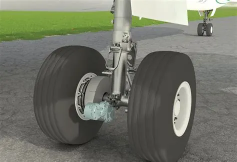
6. A. With necessary assumptions, calculate the force and power required to push / pull an aircraft by a towing vehicle.
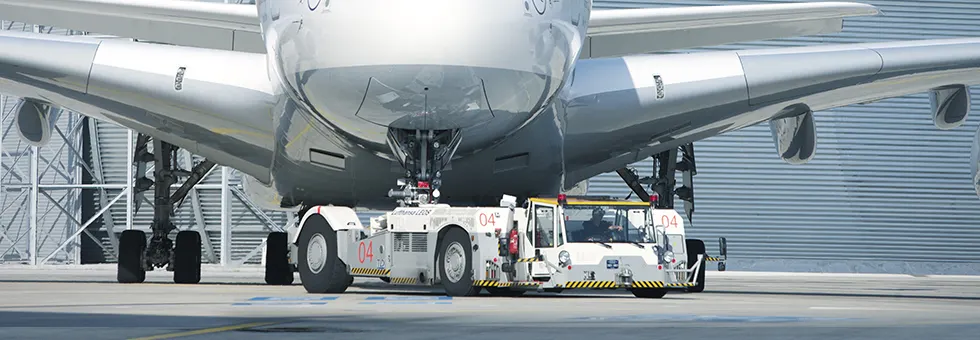
The forces required to push/ pull an aircraft by a towing are rolling resistance force and areadynamic drag force.
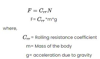
1) Rolling resistance force:- As we have discussed in part-A 5c. It is the force resisting the motion when a body (such as a ball, tire, or wheel) rolls on a surface. Its governing equation is given as
2) Aerodynamic Drag Force:-
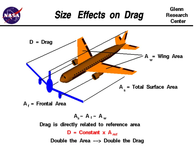
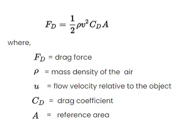
It is the force opposing the motion of the body. The drag coefficient is a common measure in automotive design as it pertains to aerodynamics. Drag is a force that acts parallel to and in the same direction as the airflow. The drag coefficient of an automobile measures the way the automobile passes through the surrounding air. When automobile companies design a new vehicle, they take into consideration the automobile drag coefficient in addition to the other performance characteristics. Aerodynamic drag increases with the square of speed; therefore, it becomes critically important at higher speeds. Reducing the drag coefficient in an automobile improves the performance of the vehicle as it pertains to speed and fuel efficiency. The governing equation of these force is given as following:
Calculation:
let us assume that,
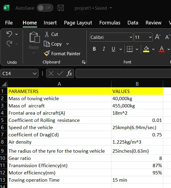
Mass of Towing Vehicle =40,000kg
Mass of aircraft=155,000kg
Total mass (m)= 40,000+155,000 = 195,000kg
Frontal Area of the aircraft (A) =18 m²
Speed of the vehicle(u) = 25kmph
converting it into m/sec
u=25 *(1000/3600)=6.9445m/sec
Drag coefficient (Cd) =0.75
Air density =1225kg/m³
Calculating Rolling resistance Force (Frr) = Crr* m*g
= 0,01*195,000*0.8
=19,110N

=0.5*1.225*10*0.75*(6.9445)^2
Therefore the total force required to push/pull the aircraft by the towing vehicle (F) =Frr+Fd
= 19,110 + 398.769
=19,508.769 N
Calculating the power(p) = Force*Velocity
= 19508.769*6.9445
=135.478 kw
B. Develop the model for the calculated force and power using Simulink.
1)constant 2)sum 3) product 4) square 5) Display
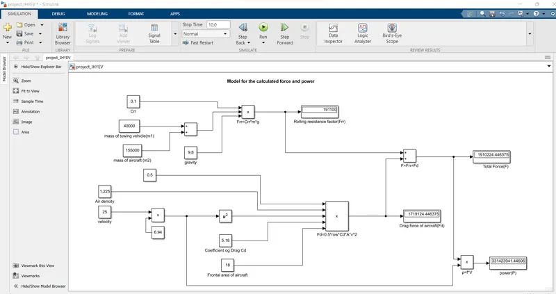
Simulink model:-
Explaination:
In order to understand the above simulink model we do reverse engineering.
• For calculating power we have to multiply both total force(F) and velocity in m/sec for this we have used 'product' block (P=F*V).
• For calculating the Total Force (F) we have added both Frr & Fd by using 'Sum block as shown in the above figure.
• To find the value of rolling resistance (Frr) we used product to multiply the values Crr, Total mass(m) & gravity (g) which are to be entered in the Constant block. Similarly for calculating Drag force (Fd) we have to multiply the velocity in m/sec,Drag coefficient, Frontal area of aircraft (A) and a constant value 0.5 which are to be entered in constant block.
• In order to convert velocity in Kmph to m/sec we have multiplied it with 5/18.
7. A. Design an electric powertrain with type of motor, it’s power rating, and energy requirement to fulfill aircraft towing application in Simulink. Estimate the duty cycle range to control the aircraft speed from zero to highest. Make all required assumptions. Prepare a table of assumed parameters. Draw a block diagram of powertrain.
Block diagram of powertrain:-
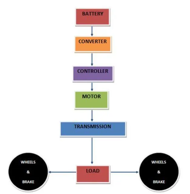
Based on the calculations done in 6A
Force required to push/pull the aircraft =19.508 KN
Power required = 135.478 kw
Let us assume,
The Radius of the Tyre for the Tug = 25inches = 0.635m
Gear ratio= 8
Transmission Effeciency (nt) =87%
Motor Efficiency (nm)= 95%
then,
Torque required for the wheels (Tw)=Total Force *Radius in meters
=19.508 *0.635 = 12.387KNm
Motor Torque= Wheel torque/(Gear ratio) =12.387/(8+0.87)
= 1.778Km
For nm=95% The required motor Torque (Tm)= 1.778/095=1.871 kNm
Similarly. The total power required by the motor considering all the officiencies (Pt) = 135478/(08770.95)=163.917Kw
Let us assume the towing operation was done for a 15 minutes (025Hrs) duration Then Total Energy consumed 163.917*025=40.90 kWh
If we consider the battery capacity 220 kw is used by the towing vehicle then, the duty cycle range to control the speed from 0 to max speed (m/s) is given as
Duty Cycle (d)=(Required Power)/ (Rated poser)=1039027/220 +0.75 Therefore the controller will be able to provide a duty cycnging from 0 to 70% in order to control the towing
Simulink Diagram of powertrain :
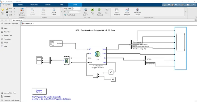
scope1 battery:
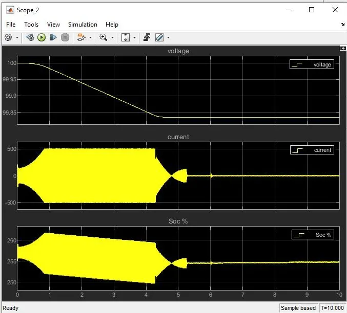
SCOPE2 output:-
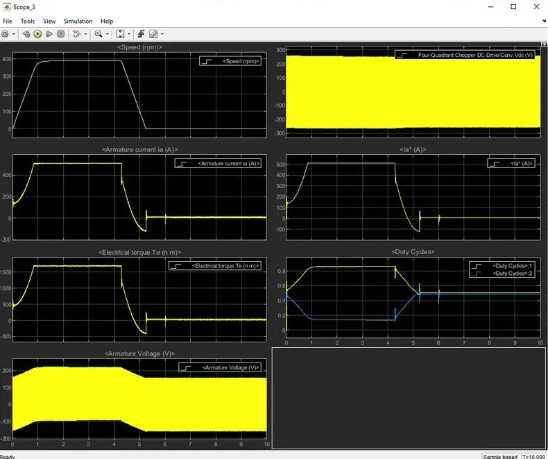
B. Disigning parameter in excel sheet