Project-1: Powertrain for aircraft in runways
Part A:
1. Search and list out the total weight of various types of aircrafts.
- Cessna 172 – Used by many as initial training aircraft (27 feet long) – 1450lbs empty weight, 2450lbs max weight
- Citation Jet M2 – (42 feet long) – 6990lbs empty weight, 10,700lbs max weight
- Boeing 767-300 – (185 feet long) – 195,000lbs empty weight, 400,000lbs max weight
- Boeing 787-800 – (186 feet long) – 264,500lbs empty weight, 502,500lbs max weight
- Boeing 777-300 – (242 feet long) – 354,000lbs empty weight, 660,000lbs max weight
- Boeing 747-400 – (232 feet long) – 407,000lbs empty weight, 910,000lbs max weight
- Airbus A320 – (123 feet long) – 82,000lbs empty weight, 170,000lbs max weight
- Airbus A330 – (210 feet long) – 274,500lbs empty weight, 507,000lbs max weight
- Airbus A380 – (240 feet long) – 610,700lbs empty weight, 1,234,600lbs max weight
2. Is there any difference between ground speed and air speed?
Ground speed is the airplane’s speed relative to the surface of the Earth,
Airspeed – at least true airspeed – is its speed relative to the air it is flying in.
Airspeed vs. Ground Speed
As mentioned above, true airspeed is simply the speed at which an aircraft is moving relative to the air it is flying in. As such, it’s also the speed at which the air is flowing around the aircraft’s wings.
Ground speed, on the other hand, is the aircraft’s speed relative to the ground. One thing that should be noted here is that it’s its horizontal rather than vertical speed – an aircraft climbing completely vertically would have a ground speed of zero.
In other words, while airspeed is what determines whether there is enough airflow around an aircraft to make it fly, ground speed is what determines how fast an aircraft will get to its destination.
Wind’s Effect on Ground Speed
The relationship between airspeed and ground speed is fairly simple. Ground speed is simply the sum of airspeed and wind speed.
If the aircraft is flying in the same direction as the wind is blowing, the aircraft experiences tailwind, and its ground speed is higher than its airspeed. On the other hand, if the wind is blowing against the direction the aircraft is traveling in, the aircraft experiences headwind, and its ground speed is lower than its airspeed.
3. Why is it not recommended to use aircraft engine power to move it on the ground at Airport?
During landing, an aircraft's engines can be set to reverse thrust mode. This helps to slow it down by acting against the aircraft's forward travel. To explain the process on a basic level, air is 'sucked' into the engines, but then instead of moving to the rear, it is ejected through new openings in the aircraft's side that 'reverse' the movement.
There are several reasons why using reverse thrust at the gate is not optimal for pushing back.
For example, the air blast around the aircraft can stir debris that may cause damage. This could affect the gate itself, other ground vehicles and aircraft, or anyone, unfortunately, standing near the plane. The ground crew would need to clear the area before the engines are activated, and this might not save any time compared to using a tug.
There is also the consideration of items being 'sucked' into the engine themselves. As the engine spins with increasing power, it creates a vortex. This could pull items such as tools into the expensive engines.
The power back operation also uses a lot of fuel and is very loud. Today, noise pollution is becoming an increasingly controversial factor of airport operations. Therefore, it is understandable that stakeholders wish to avoid this practice.
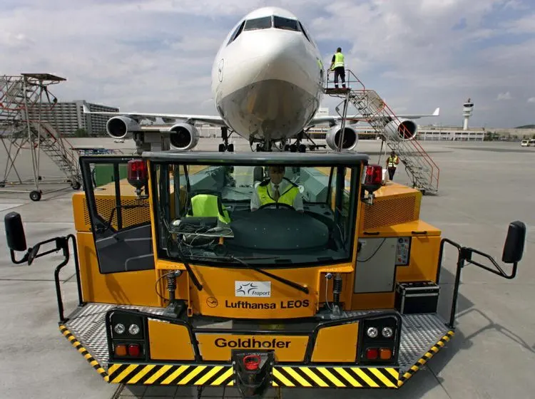
Finally, pilots in the aircraft can't see behind them, as aircraft do not have rearview mirrors like cars. As such, they would need a spotter on the ground anyway. This would negate the point of doing a movement without any help.
Simply put, it is too risky for the airport, the ground crew, and the aircraft to deploy reverse thrust that close to the terminal building. The upside is a few minutes and dollars saved, but the downside could be millions in damage and a grounded aircraft. As such, the small but mighty workhorses of an airport's tug fleet will continue to push aircraft back for the time being.
4. How an aircraft is pushed to runway when its ready to take off?
Airplanes have engines, and they can use them to move forward along the ground. So they push themselves to the runway.
It is true that most of the time, a small vehicle is needed to push the larger commercial airplanes backwards away from the terminal building, because even if a plane can reverse it’s thrust, it’s not always safe to hit the buildings with that reverse thrust. So the little trucks push the bigger planes back away from the buildings, but after that, the planes can apply a small amount of engine power to roll forward just as all airplanes can.
Aircraft push themselves to the runway.
5. Learn about take off power, tyre design, rolling resistance, tyre pressure, brake forces when landing.
Take off Power:
For light aircraft, usually full power is used during takeoff. Large transport category (airliner) aircraft may use a reduced power for takeoff, where less than full power is applied in order to prolong engine life, reduce maintenance costs and reduce noise emissions. In some emergency cases, the power used can then be increased to increase the aircraft's performance. Before takeoff, the engines, particularly piston engines, are routinely run up at high power to check for engine-related problems. The aircraft is permitted to accelerate to rotation speed (often referred to as Vr). The term rotation is used because the aircraft pivots around the axis of its main landing gear while still on the ground, usually because of gentle manipulation of the flight controls to make or facilitate this change in aircraft attitude.
Tyre design:
An aircraft tyre is designed to withstand extremely heavy loads while landing, take off, taxing, and parking. The number of wheels required for aircraft increases with the weight of the aircraft, as the weight of the aeroplane needs to be distributed more evenly.
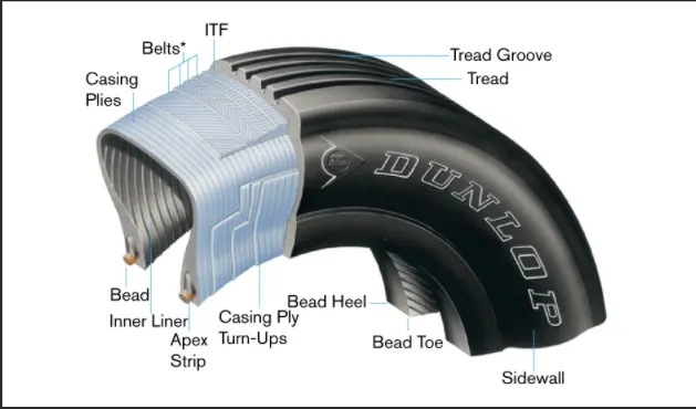
Two types of tyres used in aircraft : bias-ply tires and Radial tyres
Radial Tyres :
 |
Bias-ply Tyres:
 |
Tyre pressure:
Aircraft tires generally operate at high pressures, up to 200 psi (14 bar; 1,400 kPa) for airliners, and even higher for business jets. The main landing gear on the Concorde was typically inflated to 232 psi (16.0 bar), whilst its tail bumper gear tires were as high as 294 psi (20.3 bar).
Rolling resistance :
The friction between aircraft and runway will be proportional to the normal force exerted by the aircraft on the runway.
F = u(W-L)
The normal force will be the difference between Weight of aircraft and Lift, the friction coefficient will be typically of a magnitude of 0.02 for a standard tarmac runway.
Brake Force when Landing:
Stopping a hundresd tones of aircraft landing with very high speed requires a lot of braking forces. for braking used hydralic brake or electric brake.
hydralic brake put weight on the aircraft, now a days designer used electric brake system.
The aim of brake force when landing is to minimise a distance.
The touch down velocity of aircraft should be app. the stall speed of the aircraftin landing configuration. This will be achieved by increasing the drag and decelrate the aircraft to minimise the aircraft speed.The deceration on the landing roll from to will be accomplised by braking and reverse trust. this can be solve by the avg. accleration approach that was used to estimate the take off roll
dv/dt = -T-D-F/m
The forces involved will be,
T – Thrust of propulsion system pushing aircraft along runway.
D – Aerodynamic Drag of vehicle resisting the aircraft motion.
F – Rolling resistance friction due to the contact of wheels or skids on the ground.
So the brake force= mass * Deceleration
Part B:
6. A. With necessary assumptions, calculate the force and power required to push / pull an aircraft by a towing vehicle.
For Push/ Pull an Aircraft, three forces act on the vehicle,
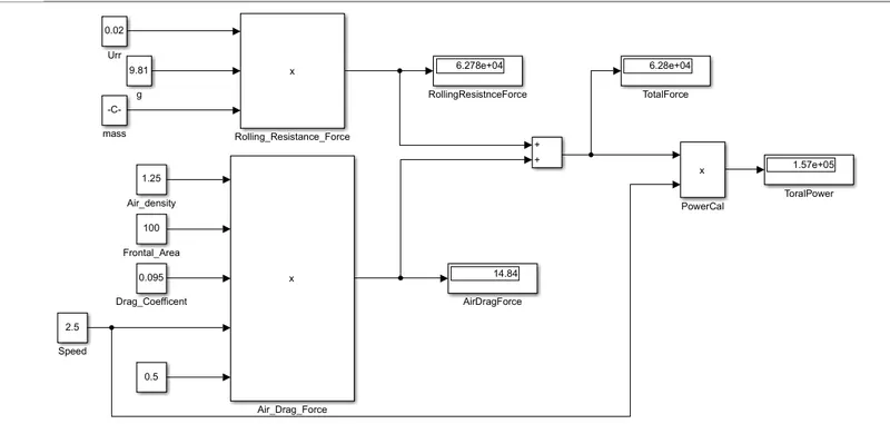
1)Rolling Resistance Force = urr*m*g
2)Aerodynamics Drag Force = 0.5* Frontal area(A)* Drag Coefficent *Air Density*Speed^2
3) Hill Clambing Force = 0 because we just pulling the vehicle in Runway
Weights and Coefficent are assume as shown in Below Table and calculate the force = 62808.41N and Power =157KW
| Power Requirement | |
| Rolling Resistance Calculation | |
| Vehicle Weight Kg | 50000 |
| Aircraft Weight Kg | 270000 |
| Coefficent of Rolling Resistance(Vehicle+Aircraft) | 0.02 |
| Rolling Resistance Force(N) | 62784 |
| Air Drag Calculation for Towering Vehicle | |
| Air Density(Kg/m3) | 1.25 |
| Width(m) | 5 |
| Height(m) | 7 |
| Frontel Area(m2) (Vehicle+Aircraft) | 35 |
| Drag Coefficent(Vehicle +Aircraft) | 0.05 |
| Speed(kmph) --> (m/s) | 2.5 |
| Air Drag Force(N) | 6.835938 |
| Air Drag Calculation for Aircraft | |
| Air Density(Kg/m3) | 1.25 |
| Width(m) | 5 |
| Height(m) | 20 |
| Frontel Area(m2) (Vehicle+Aircraft) | 100 |
| Drag Coefficent(Vehicle +Aircraft) | 0.045 |
| Speed(kmph) --> (m/s) | 2.5 |
| Air Drag Force(N) | 17.57813 |
| Total Drag Force (N) | 24.41406 |
| Total Forces | 62808.41 |
| Total Power In KW | 157.021 |
B. Develop the model for the calculated force and power using Simulink.
7. A. Design an electric powertrain with type of motor, it’s power rating, and energy requirement to fulfill aircraft towing application in Simulink. Estimate the duty cycle range to control the aircraft speed from zero to highest. Make all required assumptions. Prepare a table of assumed parameters. Draw a block diagram of powertrain.
From example 6 , we get power = 157KW
Power Input = Battery Voltage * Current
Powertain Specification:
|
Power
|
The battery voltage
|
Speed
|
Rated torque
|
Peak torque
|
Peak power
|
current
|
Peak current
|
Efficiency
|
Weight
|
|
160kw
|
360V~540V
|
3500rpm
|
437Nm
|
1000Nm
|
360KW
|
488.4A
|
900A
|
96.6%
|
580kg
|
Efficency of Motor = Power Output / Power Input
Energy required for Towering Aicraft= Required Power * Time
Assume Time= 10 mins
Energy required = 157KW*0.6 = 15.7KWph
Duty Cycle = Average Power / Peak Power
= 157KW/160KW
Duty Cycle = 98 %
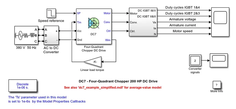
Description
The 200 HP DC motor is separately excited with a constant 150 V DC field voltage source. The armature voltage is provided by an IGBT converter controlled by two PI regulators. The converter is fed by a 515 V DC bus obtained by rectification of a 380 V AC 50 Hz voltage source. In order to limit the DC bus voltage during dynamic braking mode, a braking chopper has been added between the diode rectifier and the DC7 block.
The first regulator is a speed regulator, followed by a current regulator. The speed regulator outputs the armature current reference (in p.u.) used by the current controller in order to obtain the electromagnetic torque needed to reach the desired speed. The speed reference change rate follows acceleration and deceleration ramps in order to avoid sudden reference changes that could cause armature over-current and destabilize the system. The current regulator controls the armature current by computing the appropriate duty ratios of the 5 kHz pulses of the four IGBT devices (Pulse Width Modulation). For proper system behaviour, the instantaneous pulse values of IGBT devices 1 and 4 are opposite to those of IGBT devices 2 and 3. This generates the average armature voltage needed to obtain the desired armature current. In order to limit the amplitude of the current oscillations, a smoothing inductance is placed in series with the armature circuit.