Week - 4
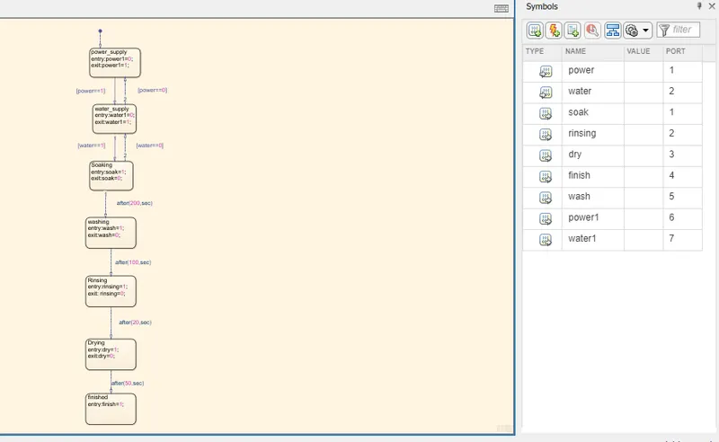
- Implement control logic of a “washing machine” using Stateflow as per given sequence:
- If the power supply is available, the system gets activated
- If the Water supply is not available, stop the process & indicate through LED
- Soaking time should be 200s followed by Washing time of 100s.
- Then rinsing happens for next 20s & dryer runs for 50s
Solution :
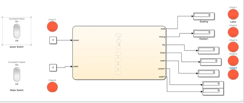
Condition 1 : Power =0 and Water = 0 : Machine is not working
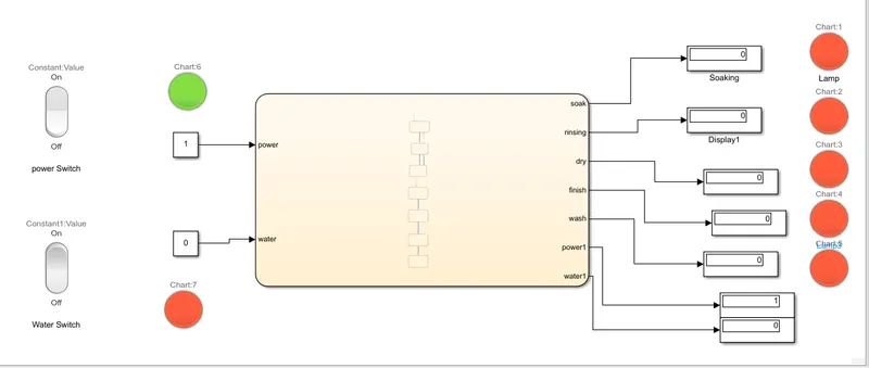
Condition 2 : Power =1 and water =0 - Machine is not working
Condition 3 : Power =0 and water =1 : machine is not working
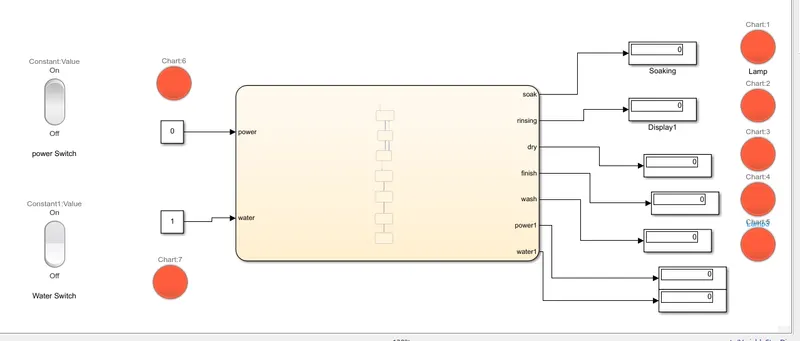
Condition 4 : Power =1 and Water= 1 : machine is working
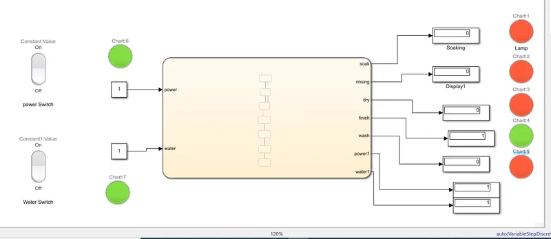
only this condition, all processes is work well and respective lamp will be Green with specific time and after finishing specific time lamp become RED and finally finish Lamp = Green.
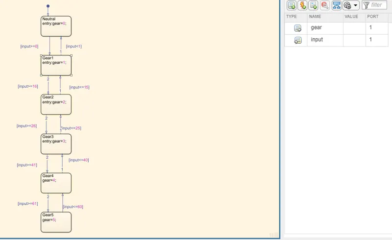
2. Make a Simulink chart for the “Gear shift” logic as per below conditions:
Speed Range(kmph) Gear
0 to 15 1
16 to 25 2
26 to 40 3
41 to 60 4
Above 61 5
Give speed input while the simulation is running & display the gear number.
Solution : Chart:
Flow chart of Gear Shift System :
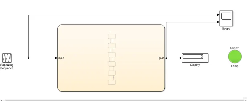
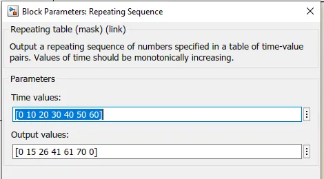
1) Repeating Sequence is used to give different speeds
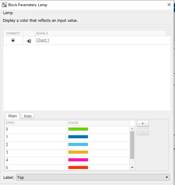
2)Display is used to show which gear is working and Lamp is used to show differnt colour for each gear system.
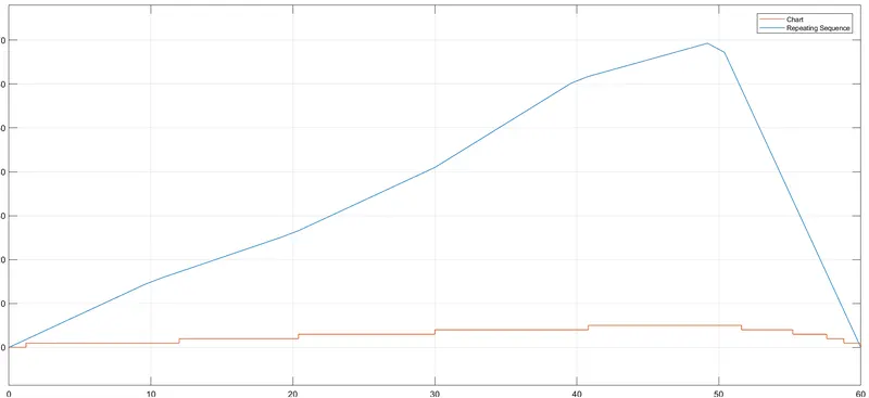
Scope is used to show the input and output waveform.