Project-1: Powertrain for aircraft in runways
Project-1: Powertrain for aircraft in runways
Study Case:
Part A:
1. Search and list out the total weight of various types of aircrafts.
2. Is there any difference between ground speed and air speed?
3. Why is it not recommended to use aircraft engine power to move it on the ground at Airport?
4. How an aircraft is pushed to runway when its ready to take off?
5. Learn about take off power, tyre design, rolling resistance, tyre pressure, brake forces when landing.
Part B:
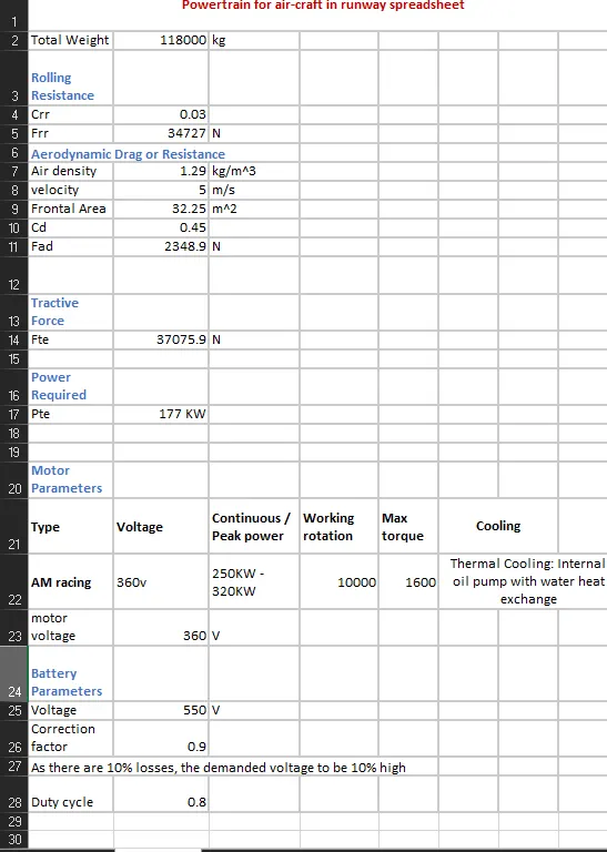
6. A. With necessary assumptions, calculate the force and power required to push / pull an aircraft by a towing vehicle.
B. Develop the model for the calculated force and power using Simulink.
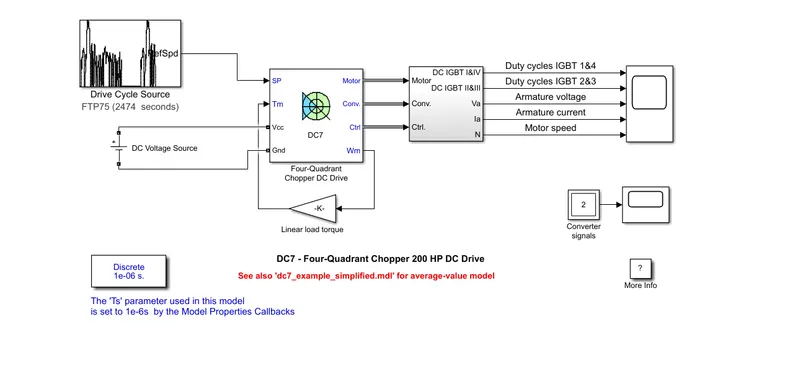
7. A. Design an electric powertrain with type of motor, it’s power rating, and energy requirement to fulfill aircraft towing application in Simulink. Estimate the duty cycle range to control the aircraft speed from zero to highest. Make all required assumptions. Prepare a table of assumed parameters. Draw a block diagram of powertrain.
(Hint :DC7 Block)
B. Also, Design the parameters in excel sheet.
Part 1:
Study case 1: Search and list out the total weight of various types of aircrafts.
| MTOW = Maximum take-off weight, MLW = Maximum landing weight, TOR = Take-off run (SL, ISA+15°, MTOW), LR = Landing run (SL, ISA+15°, MLW) | ||||||||||||
| Type | MTOW [kg] | MLW [tonnes] | TOR [m] | LR [m] | ICAO category | FAA category | ||||||
| Antonov An-225 | 6,40,000 | 591.7 | 3500 | Heavy | Super | |||||||
| Scaled Composites Model 351 Stratolaunch | 5,89,670 | 3660 | Heavy | Super | ||||||||
| Airbus A380-800[1][2][3] | 5,75,000 | 394 | 3100 | 1930 | Super | Super | ||||||
| Boeing 747-8F | 4,47,700 | 346.091 | 3100 | 1800 | Heavy | Heavy | ||||||
| Boeing 747-8 | 4,43,613 | 306.175 | 3100 | Heavy | Heavy | |||||||
| Boeing 747-400ER | 4,12,770 | 295.742 | 3090 | Heavy | Heavy | |||||||
| Antonov An-124-100M | 4,05,060 | 330 | 2520 | 900 | Heavy | Heavy | ||||||
| Boeing 747-400 | 3,96,900 | 295.742 | 3018 | 2179 | Heavy | Heavy | ||||||
| Lockheed C-5 Galaxy[4][5][6] | 3,81,000 | 288.417 | 2530 | 1494 | Heavy | Heavy | ||||||
| Boeing 747-200[7] | 3,77,840 | 285.7 | 3338 | 2109 | Heavy | Heavy | ||||||
| Boeing 747-300[7] | 3,77,840 | 260.32 | 3222 | 1905 | Heavy | Heavy | ||||||
| Airbus A340-500[8] | 3,71,950 | 240 | 3050 | 2010 | Heavy | Heavy | ||||||
| Airbus A340-600[8] | 3,67,400 | 256 | 3100 | 2100 | Heavy | Heavy | ||||||
| Boeing 777F | 3,47,800 | 260.816 | 2830 | Heavy | Heavy | |||||||
| Boeing 777-300ER | 3,51,800 | 251.29 | 3100 | Heavy | Heavy | |||||||
| Boeing 777-200LR | 3,47,450 | 223.168 | 3000 | Heavy | Heavy | |||||||
| Boeing 747-100[7] | 3,40,200 | 265.3 | Heavy | Heavy | ||||||||
| Airbus A350-1000 | 3,08,000 | 233.5 | Heavy | Heavy | ||||||||
| Boeing 777-300 | 2,99,370 | 237.683 | 3380 | Heavy | Heavy | |||||||
| Boeing 777-200ER | 2,97,550 | 213 | 3380 | 1550 | Heavy | Heavy | ||||||
| Airbus A340-300[8][9] | 2,76,700 | 190 | 3000 | 1926 | Heavy | Heavy | ||||||
| McDonnell Douglas MD-11 | 2,73,300 | 185 | 2990 | 1890 | Heavy | Heavy | ||||||
| Airbus A350-900 | 2,70,000 | 175 | 2670 | 1860 | Heavy | Heavy | ||||||
| Ilyushin Il-96M | 2,70,000 | 195.04 | 3115 | 2118 | Heavy | Heavy | ||||||
| McDonnell Douglas DC-10 | 2,56,280 | 183 | 2990 | 1890 | Heavy | Heavy | ||||||
| Boeing 787-9[10] | 2,54,000 | 192.777 | 2900 | Heavy | Heavy | |||||||
| Boeing 787-10[10] | 2,54,000 | 201.849 | Heavy | Heavy | ||||||||
| Airbus A340-200[8][11] | 2,53,500 | 181 | 2990 | Heavy | Heavy | |||||||
| Airbus A330-900 | 2,51,000 | 1,91,000 | 3100 | Heavy | Heavy | |||||||
| Ilyushin IL-96-300 | 2,50,000 | 175 | 2600 | 1980 | Heavy | Heavy | ||||||
| Airbus A330-300[12][13] | 2,42,000 | 185 | 2500 | 1750 | Heavy | Heavy | ||||||
| Airbus A330-200[12][13] | 2,42,000 | 180 | 2220 | 1750 | Heavy | Heavy | ||||||
| Lockheed L-1011-500 | 2,31,300 | 166.92 | 2636 | Heavy | Heavy | |||||||
| Boeing 787-8[10] | 2,28,000 | 172.365 | 3300 | 1695 | Heavy | Heavy | ||||||
| Lockheed L-1011-200 | 2,11,400 | Heavy | Heavy | |||||||||
| Ilyushin IL-86 | 2,08,000 | 175 | Heavy | Heavy | ||||||||
| Boeing 767-400ER | 2,04,000 | 158.758 | 3414 | Heavy | Heavy | |||||||
| Airbus A300-600R[14] | 1,92,000 | 140 | 2385 | 1555 | Heavy | Heavy | ||||||
| Boeing 767-300ER | 1,87,000 | 136.08 | 2713 | 1676 | Heavy | Heavy | ||||||
| Concorde | 1,85,000 | 111.1 | 3440 | 2220 | Heavy | Heavy | ||||||
| Airbus A300-600[14] | 1,63,000 | 138 | 2324 | 1536 | Heavy | Heavy | ||||||
| Boeing 767-300 | 1,59,000 | 136.078 | 2713 | 1676 | Heavy | Heavy | ||||||
| Airbus A310-300[14] | 1,57,000 | 124 | 2290 | 1490 | Heavy | Heavy | ||||||
| Vickers VC10 | 1,52,000 | 151.9 | Heavy | Heavy | ||||||||
| Boeing 707-320B[15] | 1,51,000 | 97.5 | Heavy | Heavy | ||||||||
| Boeing 707-320C[15] | 1,51,000 | 112.1 | Heavy | Heavy | ||||||||
| Douglas DC-8-61 | 1,47,000 | Heavy | Heavy | |||||||||
Study Case 2: Is there any difference between ground speed and air speed ?
Wind Speed
For a reference point picked on the ground, the air moves relative to the reference point at the wind speed. Notice that the wind speed is a vector quantity and has both a magnitude and a direction. Direction is important. A 20 mph wind from the west is different from a 20 mph wind from the east. The wind has components in all three primary directions (north-south, east-west, and up-down). In this figure, we are considering only velocities along the aircraft's flight path. A positive velocity is defined to be in the direction of the aircraft's motion. We are neglecting cross winds, which occur perpendicular to the flight path but parallel to the ground, and updrafts and downdrafts, which occur perpendicular to the ground.
Ground Speed
For a reference point picked on the ground, the aircraft moves relative to the reference point at the ground speed. Ground speed is also a vector quantity so a comparison of the ground speed to the wind speed must be done according to rules for vector comparisons.
Airspeed
The important quantity in the generation of lift is the relative velocity between the object and the air, which is called the airspeed. Airspeed cannot be directly measured from a ground position, but must be computed from the ground speed and the wind speed. Airspeed is the vector difference between the ground speed and the wind speed.
Airspeed = Ground Speed - Wind Speed
On a perfectly still day, the airspeed is equal to the ground speed. But if the wind is blowing in the same direction that the aircraft is moving, the airspeed will be less than the ground speed.
Study Case 3: Why is it not recommended to use aircraft engine power to move it on the ground at Airport?
airplanes are equipped with engines rated from 18,000 to nearly 100,000 lb of thrust. Such thrust levels provide for safe takeoff, flight, and landing over a wide range of temperatures, altitudes, gross weights, and payload conditions. However, the exhaust wake from these engines can pose hazards in commercial airport environments. Operators and airport authorities must carefully consider these hazards and the resulting potential for injury to people and damage to or caused by baggage carts, service vehicles, airport infrastructure, and other airplanes.
Power Hazard Areas
When modern jet engines are operated at rated thrust levels, the exhaust wake can exceed 375 mi/h (325 kn or 603 km/h) immediately aft of the engine exhaust nozzle. This exhaust flow field extends aft in a rapidly expanding cone, with portions of the flow field contacting and extending aft along the pavement surface (fig. 1). Exhaust velocity components are attenuated with increasing distance from the engine exhaust nozzle. However, an airflow of 300 mi/h (260 kn or 483 km/h) can still be present at the empennage, and significant people and equipment hazards will persist hundreds of feet beyond this area. At full power, the exhaust wake speed can typically be 150 mi/h (130 kn or 240 km/h) at 200 ft (61 m) beyond the airplane and 50 to 100 mi/h (43 to 88 kn or 80 to 161 km/h) well beyond this point
Foreign Object Damage
Foreign object damage (FOD) caused by high engine thrust can affect airport operations as it relates to
- Airplane structure.
- Flight controls.
- Equipment and personnel.
Abover are the reasons why a towing vehicle is used for moving areoplanes for short distances and in reverse direction
Study Case 4: How an aircraft is pushed to runway when its ready to take off?
Airplanes have engines, and they can use them to move forward along the ground. So they push themselves to the runway.
It is true that most of the time, a small vehicle is needed to push the larger commercial airplanes backwards away from the terminal building, because even if a plane can reverse it’s thrust, it’s not always safe to hit the buildings with that reverse thrust. So the little trucks push the bigger planes back away from the buildings, but after that, the planes can apply a small amount of engine power to roll forward just as all airplanes can.
Study Case 4:Learn about take off power, tyre design, rolling resistance, tyre pressure, brake forces when landing ?
-
Engine thrust = 284 kN
-
Takeoff speed = 170 knots
-
Takeoff power = 90% max power
Exact Calculation:
3.Tyre design:
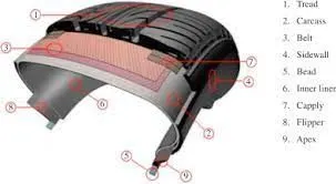
Design and Construction of Aircraft tyre
-
They support the weight of an aircraft while it is on the ground.
-
It also provides the necessary traction for braking and stopping of an aeroplane.
-
Tyre also helps to absorb the shock of landing and provide cushioning the roughness of takeoff, roll-out, and taxi operations.
Spoilers
Reverse thrust
irst, some requirement assumptions . . .
Landing weight = takeoff weight in case of aborted takeoff = 1500 lbf
Landing distance = 500 ft
Speed (assume aborted takeoff) = 60 kt (100 ft/sec)
We will use Newton’s second law to determine force due to deceleration:
Deceleration: from simple kinematics, acceleration = velocity^2 / distance
= (100 ft/s)^2 / 500 ft = 20 ft / s^2
Mass of aircraft = (weight) / g = 1500/32.2 = 46.58 lbf*s^2 / ft
Force = mass * acceleration (46.58 lbf*s^2/ft) * (20 ft / s^2) = 931.6 lbf
So in this example, the braking (deceleration) force is 931.6 lbf
Part B:
6. A. With necessary assumptions, calculate the force and power required to push / pull an aircraft by a towing vehicle.
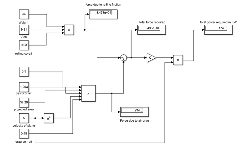
Simulink Model:
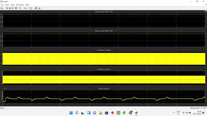
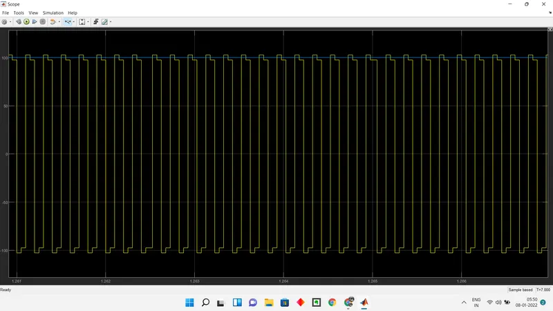
Clear Obeservation of switching of gates in controller, Voltage variations and motor speeds.
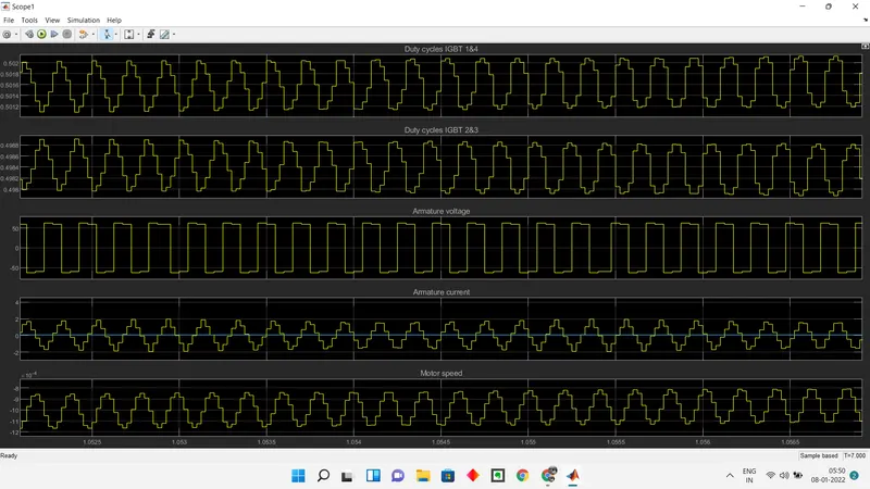
Converter signals: