Project-1: Powertrain for aircraft in runways
1. Search and list out the total weight of various types of aircrafts.
Maximum Take off Weight (MTOW)
The maximum takeoff weight (also known as the maximum brake-release weight) is the maximum weight authorised at brake release for
takeoff, or at the start of the takeoff roll. The maximum takeoff weight is always less than the maximum taxi/ramp weight to allow for fuel
burned during taxi by the engines and the APU.
Maximum Landing Weight (MLW)
The maximum weight authorised for normal landing of an aircraft. The MLW must not exceed the MTOW.
Let us list out the MTOW and MLW of few notable aircrafts.
Aircraft type MTOW (kg) MLW (tonnes)
Airbus A220-300 59,000 50.80
Airbus A300-600 163,000 138
Airbus A320 68,000 66
Airbus A330-300 242,000 185
Airbus A340-600 367,400 256
Antonov An-225 640,000 591.7
ATR 72-600 22,800 22.35
Boeing 727-200 78,000 68.1
Boeing 737-700 70,000 58.06
Boeing 747-400 396,900 295.742
Boeing 777-300 299,370 237.683
Concorde 185,000 111.1
For weights of more aircrafts,refer this link
https://en.wikipedia.org/wiki/List_of_airliners_by_maximum_takeoff_weight
2. Is there any difference between ground speed and air speed?
Ground Speed:
Ground speed, is how fast an airplane's shadow would move across the land. If there's a strong wind pushing an aircraft, that's
reflected in the ground speed.
Airspeed:
Airspeed, is how fast an airplane is flying strictly under its own power, which is calculated by subtracting the wind speed from the
ground speed.
3. Why is it not recommended to use aircraft engine power to move it on the ground at Airport?
It is not recommended to use Full engine power to move the aircraft in the airport because of safety reasons and to prevent hazards.
However, when we are assuming passenger commuter aircraft and large airliners, Aircraft move using their own engine power (Limited
Power) all the time on the airport apron and taxiways under their own power to go towards runways and after landing taxi to their assigned
gate.
The only time they use external assistance is to pushback from the gate. Large turbofan aircraft need help to reverse via a pushback
tractor. The engines are turned on after the pushback is complete and the aircraft can move forward under It’s own power.
To be accurate, some aircraft can reverse using a variable pitch prop or thrust reversing on turbofans but generally reversing is done
via pushback tractors. Blasting jet reversers blows debris In the crowded gate area creating foreign object damage hazard for adjacent
aircraft, gate equipment or terminal waiting area glass windows.
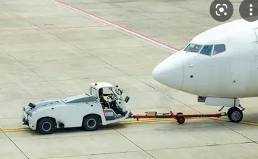
The above image shows pushbak tractor.
4. How an aircraft is pushed to runway when its ready to take off?
Airplanes have engines, and they can use them to move forward along the ground. So they push themselves to the runway. It true
that most of the time, a small vehicle is needed to push the airplane backwards away from the terminal building, because even if a plane
can reverse it’s thrust, it’s not always safe to hit the buildings with a jet blast. So the little trucks push the jets back away from the
buildings, but after that, the plane can apply a small amount of engine power to roll forward.
5. Learn about take off power, tyre design, rolling resistance, tyre pressure, brake forces when landing.
Take Off Power:
Reduced power or derated takeoffs are normal and frequently used. The performance is carefully calculated prior to each takeoff, ensuring
that the proper speeds, power settings and flaps are used for the weight of the takeoff on the runway intended and at the proper
temperature. When using this method during takeoff, it is always possible to increase to full power if the situation requires. The captain
always makes the final decision whether to use full thrust or derate.
Derates improve engine life and reliability. In addition to lowering operating costs, they decrease the likelihood of an engine failure. All
jets use some form of derated or reduced-thrust takeoffs.
Take off performance can be predicted using a simple measure of the acceleration of the aircraft along the runway based on force
equilibrium.
The forces involved will be,
T – Thrust of propulsion system pushing aircraft along runway.
D – Aerodynamic Drag of vehicle resisting the aircraft motion.
F – Rolling resistance friction due to the contact of wheels or skids on the ground.
During take-off run the imbalance in these forces will produce an acceleration along the runway.
It should be taken care that the acceleration overcomes the aerodynamic drag and the rolling resistance friction.
Therefore,
Acceleration, dV/dt = (T-D-F) / M
where M is the Mass of the aircraft.
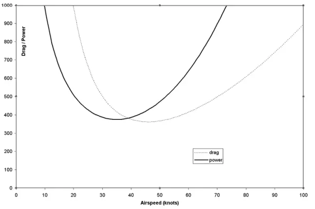
The below graph shows the airspeed vs power required
Tyre Design:
Designing aircraft tires is a very intense undertaking. Once an aircraft manufacturer goes to the tire manufacturer with the size and
weight requirements, the tire manufacturer begins the process of designing a tire that meets the needs of the aircraft manufacturer as well
as all regulatory requirements — including foreignregulations in many cases.
Engineers are challenged with designing tires with cool running, heat-resistant materials while simultaneously exceeding tire service
requirements. Tire prototypes are put through rigorous tests that simulate cycles of landings, take-offs, and taxi operations. It is only after
the tires pass all mandatory tests and meet the requirements of the aircraft manufacturer and airworthiness authorities that the tires are
put into production.
Rolling Resistance
Rolling resistance is the force resisting the motion when a body(such as ball, tyre or wheel) rolls on a surface. The physical effect of
rolling resistance can be seen in the aircraft when aircraft takes off from the runway and while landing at the runway with the help of their
wheels.
Rolling resistance can be expressed as Frr= μrr.m.g
Frr,where is the rolling resistance force,
μrr, is the coefficient of rolling resistance
m s the mass (in kg)
g is the acceleration due to gravity.
Tyre Pressure:
Aircraft tires generally operate at high pressures, up to 200 psi (14 bar; 1,400 kPa) for airliners, and even higher for business jets. The
main landing gear on the Concorde was typically inflated to 232 psi (16.0 bar), whilst its tail bumper gear tires were as high as 294 psi
(20.3 bar). The high pressure and weight load on the Concorde tyres were a significant factor in the loss of Air France Flight 4590.
Tests of airliner aircraft tires have shown that they are able to sustain pressures of maximum 800 psi (55 bar; 5,500 kPa) before
bursting. During the tests the tires have to be filled with water, to prevent the test room being blown apart by the energy that would be
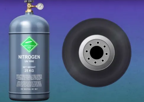
released by a gas when the tire bursts. Aircraft tires are usually inflated with nitrogen to minimize expansion and contraction from extreme
changes in ambient temperature and pressure experienced during flight. Dry nitrogen expands at the same rate as other dry atmospheric
gases (normal air is about 80% nitrogen), but common compressed air sources may
contain moisture, which increases the expansion rate with temperature. The requirement that an inert gas, such as nitrogen, be used
instead of air for inflation of tires on certain transport category airplanes was prompted by at least three cases in which the oxygen in air-
filled tires had combined with volatile gases given off by a severely overheated tire and exploded upon reaching autoignition temperature.
The use of an inert gas for tire inflation eliminates the possibility of tire explosion.
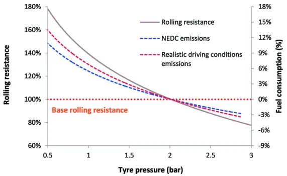
The below graph shows the relation between tyre pressure and the rolling resistance:
Brake Forces when Landing:
An aircraft lands at a speed close to 250 Kmph. Hence it becomes necessary to resist its speed within a minimum stipulation of time
to bring the aircraft to the
rest position. The braking devices which are used to deaccelerate the aircraft are:
1.) Wheel brakes (Including Anti Skid systems and Anti brake systems)
2.) Spoilers
3.) Reverse Thrust
Part B
6A. With necessary assumptions, calculate the force and power required to push / pull an aircraft by a towing vehicle.
Let us the consider the scenario of push the Airbus A320-200 (World's most predominantly used Passenger Aircraft).
Weight of Airbus A380= 79 tonnes= 79,000 Kgs
Let us consider the towing vehicle to be Mototok Spacer 8600
Weight of the Mototok Space 8600= 5400 Kgs. (from the data sheet)
Let us analyse various forces to be overcome to push the aircraft.
1. Rolling resistance force
Frr= μrr.m.g
let μrr =0.002
That implies Frr= 0.002*79000= 158 N
Frr of Mototok towing vehicle= 0.002*5400=10.8 N
2.Aerodynamic resistance force:
Let us assume that speed of pushback or pushforward is 5.4 km/hr. (i.e 1.5 m/s) [From the datasheet]
Let,
Drag coefficient (Cd)= 0.025
Air Density = 1.125 kg/m^3.
Frontal Area (A): 150 m^2
Velocity (V)= 5.4 kmph or 1.5 m/s
Frr = 1/2 * Cd * ρ * v^2
Frr = 1/2 * 0.025 * 1.125 * 150 * 1.5^2
therefore, airdrag force is 4.74 N
Hill climb resistance
The taxiways on the airport are constructed flat. Hence gradient or hill climb force is neglected.
Inertia force of the aircraft
Mass of the aircraft= 79000/9.8= 8061.22 kg
Inertial force of the aircraft= m(v/t) where t is the towing time.
Let the towing time be 30 seconds.
That implies inertial force of the aircraft is 8061.22*(1.5/30)= 403 N
Inertial force of the Towing Vehicle
Mass of the towing vehicle= 5400/9.8= 551 kg
Inertial force = 551* (1.5/30)= 27.55 N
Therefore, Total force requirement is 158+10.8+4.74+403+27.55= 604.09 N= 610 N (approx)
Power Required
P = F*v
P = 610*1.5 = 915 W
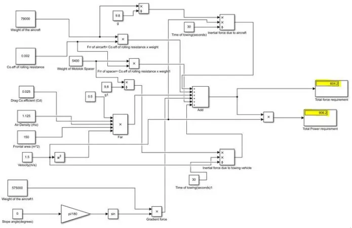
B. Develop the model for the calculated force and power using Simulink.
The simulink model is developed is shown below.
7A. Design an electric powertrain with type of motor, it’s power rating, and energy requirement to fulfill aircraft towing
application in Simulink. Estimate the duty cycle range to control the aircraft speed from zero to highest. Make all required
assumptions. Prepare a table of assumed parameters. Draw a block diagram of powertrain.
Assumptions
for doing this problem, i have considered the values realated to aircraft like -
aircraft weight = 31298 kg
towing tractor = 1100kg
coefficent of drag = 0.02
coefficent of rolling resistance = 0.03
frontal area = 158.3
Rolling resistance coefficent = 0.03
Velocity = 10km/hr =3 m/sec
Power = 19000 pound-force = 84.516 KN = 84516.21 N
towing tractors wheel radius = 0.35m
gear ratio = 20
velocity = 10km/hr = 3m/sec
density of air = 1.25kg/m^3
acceleration of gravity = 9.81m/sec^2
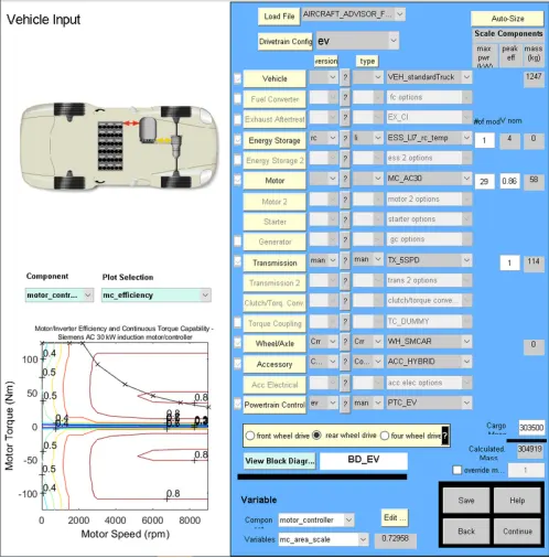
i have used the advisor tool to design the motor ratings.
Type of Motor and Motor Power ratings
motor specifications and rating
motor model - MC_AC30, Siemens AC 30 kW induction motor/controller
Maximum power - 250KW
Efficiency - 86%
Mass of motor - 58Kg
Voltage - 216V
Peak current - 280A
Minimum Voltage - 140V
clear all
close all
clc
%ASSUMED VALUES
urr = 0.03;
u = 0.2;
ma = 31298;
mt = 1100;
g = 9.81;
rho = 1.25;
A = 158.3;
cd =0.02;
v = 3;
r = 0.35;
G = 20; %gear ratio
%FORCE CALCULATION
frr = urr*(ma+mt)*g;
fad = 0.5*rho*A*cd*v^2;
ffr = u*(ma+mt)*g;
%TRACTION FORCE CALCULATION
Traction_force_in_N = (frr + fad + ffr) %total traction force in N
%POWER CALCULATION
Power_KW = (Traction_force_in_N * v)/1000 %aircraft power calculation KW
Output
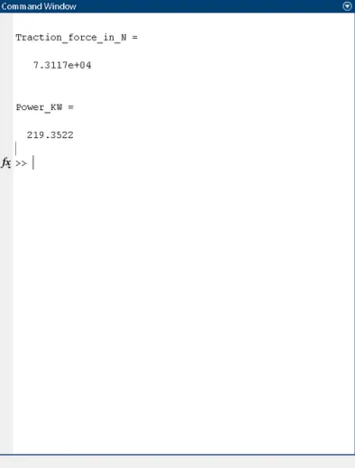
so the Output power required to pull the aircraft & the towing tractor will be 219.3522 KW
And the selcted motors power rating is 250KW, which becomes the input power required by the motor.
Hence the duty cycle range is calculated by finding the ratio of output to input power
Pout/Pin = 219.3522/250 = 0.874
so we can say the duty ycle range is from 0 to 87.77% .
Now, assume that the tractor takes 10 min or 600sec to taxing (i.e. tow the aircraft from gate to runway)
Hence the energy requirement to fulfill aircraft towing application (E) = pout * t
E = 219.3522 * 600
E = 131.611 MJ
Files link :
https://drive.google.com/drive/folders/16FUV1lQtPeCGoMfGplnMouL0-_gdlWRA?usp=sharing