Project-1: Powertrain for aircraft in runways
Q1 : Search and list out the total weight of various types of aircrafts.
A1 : The different types of aircraft are as follows :
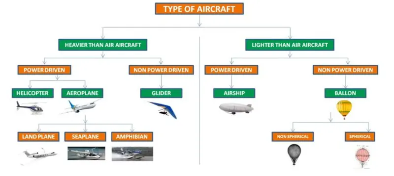
The total weight of various aircraft is given as follows:
Aircraft come in numerous weight categories and can accommodate a variety of tasks, from delivering heavy objects to remote construction sites, to carrying water during the fire season. In most cases, the bigger the aircraft, the heavier it will be. However, a heavier aircraft will need a more powerful propulsion system to generate and maintain lift. Due to the flight characteristics of the aircraft, one would think that they must be pretty light. However, depending on the configuration, they may be quite heavy.
Helicopter :
A helicopter can weigh as litle as 298 pounds (135 kg), up to as much as 33.230 pounds (15,070 kg), in empty weight. The weight of a helicopter varies by the type, model, and primary use intended for the aircraft.
Airplane :
The Boeing 737-800 is an example of an average-sized airplane. It has a maximum takeoff weight of about 80.000 kg (175.000 lbs). This includes the weight of the plane, which is about 41,000 kg (90,000 lbs), and the weight of the fuel which is about 18,000 kg (40.000 lbs). This leaves about 20,000 kg (45,000 lbs) for passengers, cargo, and crew.
Glider :
most single-seat gliders with 15m wingspans have empty weights around 550 lbs (250kg). The pilot and their equipment (parachute, drinking water, personal gear) typically add around 220 lbs (100kg).
Airship :
Without its lifting gas, an enmpty Blimp weighs almost 20,000 Ibs. Once in flated with helium and after accounting for fuel., payload, and ballast, it usually weighs in at 100-200 lbs.
Air ballon :
A typical hot-air balloon has a total mass of 545 kg. including passengers in its basket, and holds 2.55 x 10' m' of hot air in its envelope.
Q2 : is there any difference between ground speed and air speed?
A2 : 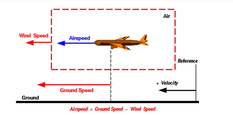
Ground speed :
Ground speed is the horizontal speed of an aircraft relative to the ground. An aircraft heading vertically would have a ground speed of zero.
Ground speed can be determined by the vector sum of the aircraft's true airspeed and the current wind speed and direction; a headwind subtracts from the ground speed, while a tailwind adds to it. Winds at other angles to the heading will have components of either headwind or tailwind as well as a crosswind component.
Wind Speed :
Fora reference point picked on the ground, the air moves relative to the reference point at the wind speed. A positive velocity s defined to be in the direction of the aircrafts motion. We are neglecting cross winds, which occur perpendicular to the flight path but parallel to the ground, and updrafts and downdrafts, which ocCur perpendicular to the ground.
Airspeed :
The important quantity in the generation of lift is the relative velocity between the object and the air, which is called the airspeed. Airspeed cannot be directly measured from a ground position, but must be computed from the ground speed and the wind speed. Airspeed is the vector difference between the ground speed and the wind speed.
Airspeed=Ground Speed-Wind Speed :
The aireraft usually operates on land as well as in air and so we need to study their speed differences in-ground and in air.
The ground speed and the airspeed usually change based on the wind component. If we consider that there is no wind component the, ground speed = airspeed.
If the wind is blowing in the tail direction of the aircraft then, (airspeed>ground speed) so,
airspeed = ground speed+ wind component.
If the wind is blowing in the head direction of the aircraft then, (airspeed
airspeed = ground speed-wind component.
Also, gravity plays a major role in increasing the aircraft's speed while it is descending.
Here wind speed is the vector difference between ground and airspeed. On a particular day, the wind speed may be zero and it is equal to the ground speed.
If the measured airspeed is greater than the observed ground speed the wind speed becomes positive.
Q3 : Why is is not recomended to use aircraft engine power to move it on the ground at airport?
A3 : It not recommended to use aircraft engine power to move it on the ground at the Airport, due to the following reasons.
- noise : these engines make huge noise which causes noise pollution to environment around.
- engine wear : gravels on the ground and any other materials gets sucked up by the engine and destroys it and also if any bird that is flying on the runway might the engine as well.
- fuel saving : 30mins of engine running is equal to 75kg of fuel burnt out.
So when airplanes are on the ground the process of moving them is called Airplane Towing.
Q4 : How an aircraft is pushed to runway when its ready to take off?
A4 :
- Taxing refers to movement of an aircraft on the ground, under its own power. The aircraft moves on wheels. An airplane uses taxiways to taxi from one place on an airport to another. like moving from terminal to the runway.
- When aircraft is ready with all the passesngers and luggages the aviation is an airport procedure during which an aircraft is pushed backwards away from an airport gate by external power.
- The aircraft always moves on the ground following the yellow lines, to avoid any colision with the surrounding buildings, vehicles or other aircrafts. The taxiing motion has a speed limit. Before making a turn the pilot reduces the speed further to prevent tire skids.
- The thrust to propel the aircraft fonward comes from its propellers or jet engines. Steering is achieved by turning a nose wheel or tail wheel/rudder.
- The use of engine thrust near terminals is restricted due to the possibility of jet blast damage. This is why the aircrafts are pushed back from the buildings by a vehicle before they can start their own engines for taxxing.

- Pushbacks are carried out by special,low profile vehicles called pushback tractors or tugs.
- These are heavy weighting low profile vehicles with enourmous torque to do the job of pushing/pilling the large aircraft from the terminals to the runway.
- The tractors are designed with extra weight purposely to offer them enough traction to push/pull heavy aircraft.
Q5 : Learn about take off power,tyre design ,rolling resistance,tyre pressure,brake forces when landing.
A5 : Take off power :
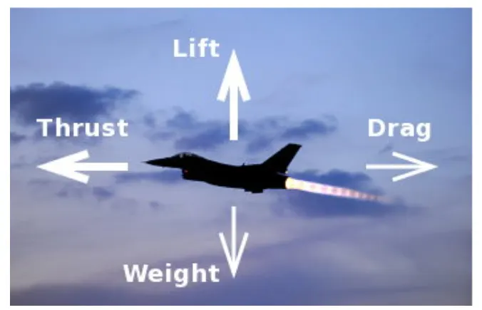
- Take off is the phase of flight in which an aerospace vehicle leaves the ground and becomes airborne. For aircraft that take off horizontally this usually involves starting with a transistion from moving along the ground on a runway.
- The take off speed required varies with air density, aircraft gross weight and aircraft configuration. The power from the engine of the aircraft used to achieve the flight is called take off power.
- For light aircraft usually full power is used during take off. Large transport category (airliner) aircraft may use a reduced power for take off where less than full power is applied in order to prolong engine life, reduced maintenance costs and reduced noise emissions.
Tyre design :
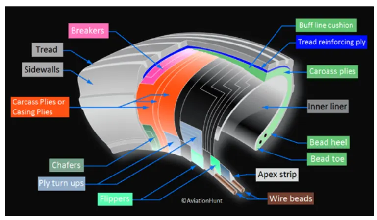
- The aircraft tyre is usually specially designed as the tyre has to withstant more load and also higher speed at the same time. The number of tyres required for any aircraft increases with aircraft's weight, as the weight of the aircraft needs to be distributed more evenly.
- Aircraft's tread pattern are designed to facilate stability in high crosswind conditions, to channel water away to de prevent hydroplanning and for braking effect. Some of the tyre design is given below.
Bias Ply Tyre :
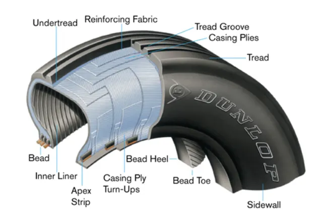
- The bias ply tyre consists of casing plies running diagonaly at approximate right angles to one another. The number of plies and angles at which they are laid dictate strength and load capacity.
- High performance bias aircraft tyres feature inter-tread reinforcing fabric (TF). This provides additional high speed stability, reduces tread distortion under load, protects the casing plies from damage and can act as wear indicators on retreadable tyres.
Radial Tyre :
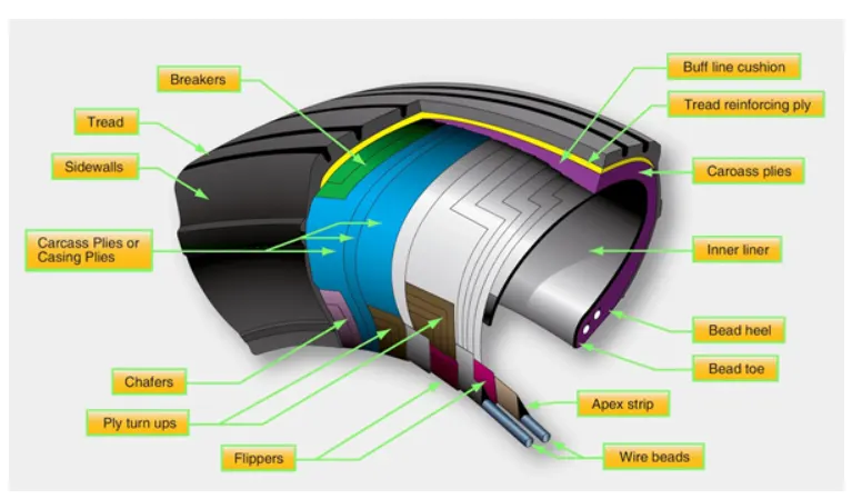
- Radial tired are the most modern design of aircraft tyres. It is a design that is similar to that of car tyres. Typically the radial tyre offers more landings per tread and lighter weight than a bias tyre, though sometimes at the expense of retread lives.
- Radial aircraft tyres differ to bias aircraft tyres in that the plies all run radially from bead to bead at approxirnately 90 degree to the center line of the tyre. Angled belt plies are laid between the tread and top casing ply, resulting in a flatter tread and adding strength to the tyre.
Rolling Resistance :
- The rolling resistance force is mainly experienced by the tyre when the vehicle moves over any surface. The rolling resistance force is given by the expression.
Frr= urr ' (m.g)
where,
(m.g) = weight in newton.
(urr) = coefficient of rolling resistance.
- The coefficient of rolling resistance (ur) depends on many factors like the, tyre pressure, tyre temperature, material of the tyre, thread pattem of the tyre and also the road roughness and liquids on the road. These factors determine the rolling resistance force.
Tyre Pressure :
- The pressure generally is very high in an aircraft tire to reduce the rolling resistance and to withstand the weight. Usually it will be around 200 to 300psi of pressure and they change based on the type of the aircraft.
- Tests of airliner aircraft tyres have shown that they are able to sustain pressures of maximum 800 psi. Aircraft tyres are usually inflated with nitrogen to minimise expansion and contraction from extreme changes in ambient temperature and pressure experienced during flight.
Brake Force while Landing :
The brake force while landing is done by three different process they are.
- Aircraft disc brakes - Aircraft has disc rotors in the landing gear used to brake the wheels while touching the ground. These brakes are operated hydraulically or pneumatically.
- Thrust reversers - Italows thrust frorm the engines to be used to slow the aircraft. This is also very effective in bringing down the speed of the aircraft by usinga negative angle plane, we are turning the wind that is coming into the propeller to flow in the opposite direction.
- Air brake - It is dedicated flight control surface that work by increasing the drag force, air brakes are designed to increase drag while making little change to lift resulting in a higher stall speed. These are some of the tyres of braking methods used to bring down the aircrafts speed while landing the flight.
Part - B:
Q6 :A : With necessary assumptions, calculate the force and power required to push/pull an aircraft by a towing vehicle.
A6 A: To push or pull an aircraft a high power motor/engine is required to overcome the huge weight of aircraft.The aircraft engine should not be in operating mode while towing process.
Only wheel brakes of aircraft in progress.
Forces to overcome on operation:
- Rolling resistance force of aircraft.
- Rolling resistance force of tug vehicle.
- Aerodynamic force acting over aircraft.
- Aerodynamic force acting on tug vehicle.
- As taxiway are in flat surfaces hill elimbing force is negleted.
- As tug should operate in very slow and steady speed acceleration force in negleted.
Formulas:
Roling resistance force, Fr-Crm'g.
where Cr = Rolling resistance coefficient,
m = Mass of vehicle,
g = Acceleration due to gravity.
Aerodynamic force, Fa-(1/2) Cd p*A*V^2.
where Cd = Drag coefficient,
p = Air density,
A = Frontal area of crossection,
V = velocity of vehicle.
Aerodynamic force,
Power F*vwhere F=Force ,v=Velocity.
Meathod to find total power requirement of tug vehicle:
To find the total power requirement we have to find,
Step 1:Fr of both tug and aircraft.
Step 2:Fa of both tug and aircraft.
Step 3:Calculate power to move aircraft and power to move tug.
Step 4:Adding powers of both tug and aircraft we can find total power requirement to push/pull aircraft.
Assumed values:
Cr of both aircraft, tug = 0.002
Mass of aircraft(Kerb payload) = 400000 Kg
Mass of tug vehhicle(Kerb payload) = 3000 Kg
g-9.8 m/s2.
Cd of both aircraft and tug -0.031
p-1125 Kg/m3.
A for aircraft-100 m2.
A for tug-20 m2.
Let vehicle to move in a speed V= 2m/s.
Calculations :
Fr of aircraft = 0.002*9.8*400000 = 7840 N.
Fr of tug = 0.002*9.8*3000 = 58.8 N.
Fa of aircraft =0.5*0.031*1.125*100"(2^2)=6.975 N.
Fa of tug = 0.5*0.031*1.125 20*(2^2) = 1.39 N.
Total force on aircraft = 7840+6.975 = 7846.975N.
Total force on tug = 58.8+1.39 = 60.19
Total power required = (sum of forces on tug and aircraft)*velocity
= (7846.975+ 60.19)*2
= 15814.33 watts
= 15.814 kw
B : Develop the model for the calculated force and power using simulink.
A6 B: Here two subsystems are created for aircraft power and tug power calculations shown below.
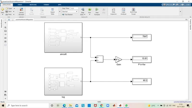
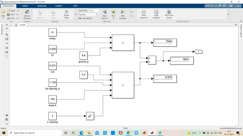
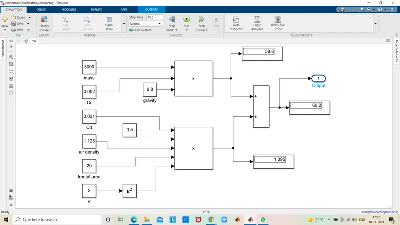
Result: The result shown as 15.81 KW in display total power.
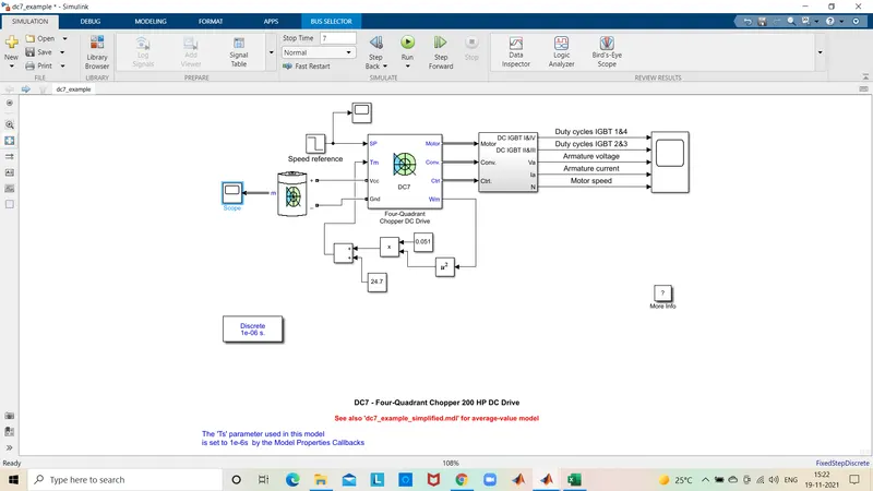
Q7 :A : Design an electric powertrain with tyre of motor, it's power rating, and energy requirements to fulfill aircraft towing application in simulink. Estimate the duty cycle range to control the aircraft speed from zero to highest. Make all required assumptions. Prepare a table of assumed parameters. Draw a block diagram of powertrain.(hint: DC7 Block)
A7 A: Tow tractor CHALLENGER 700
The CHALLENGER 700 is a conventional aircraft tractor that is capable to handle push-back, repositioning, and maintenance towing of all wide-body aircraft including a fully loaded airbus A380. The mechanical lock-up clutch of the new generation of power shift transmission reduces fuel consumption when moving at a higher speed. The liftable power- pack compartment minimizes downtime of the tractor and reduces maintenance costs.
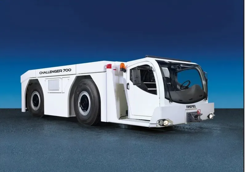
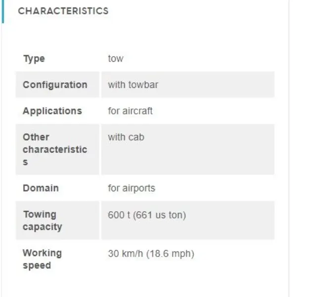
The above vehicle can tow up to a capacity of 661 ton and hence the airplane we are reffering to can be carried as it is 575 ton.
IE3 EFFICIENCY 3-PHASE INDUCTION MOTORS :
TYPE : AESV3E, AESU3E.
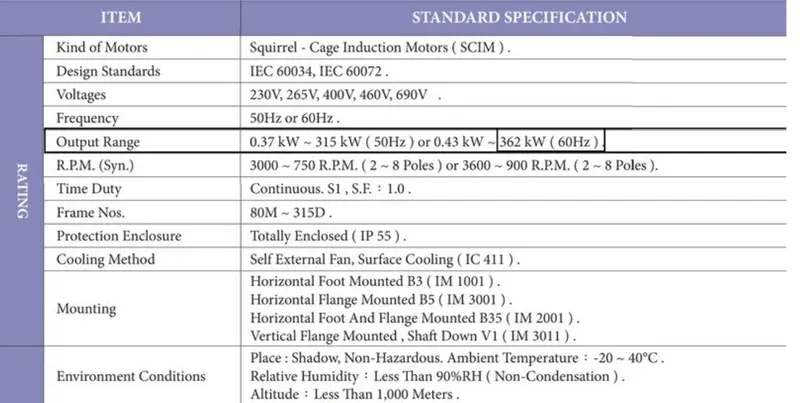
The motor is considered for the drivetrain/ powertrain.
Estimation of the duty cycle range to control the aircraft speed from zero to highest.
Assumption of power required for towing an airplane is 45.26 Kw.
Since the motor considered output power range is from 0.43KW to 362 KW.
we can choose the specifications as per our requirements.
Therefore, considering a 60KW as output power rating because we just require 45.26 KW and considering 400V.
Battery power is considered to be 550V.
The duty cycle is given by output voltage/input voltage = Vo/Vb
here, Vo is motor required voltage and Vb is battery voltage.
D = 400/550 = 0.72
as there will be losses due to the resistance.
the correction factor is considered to be 90%
as there is 10% loss, the voltage demanded by the motor should be 10% more than required.
D = 0.72(1+0.1)
so the voltage demanded should be around 440V from the battery.
Table of assumed parameters
| Assumed parameters | Values |
| Mass |
575000 kg |
| Co-efficient of rolling resistance (Crr) |
0.002 |
| Drag coefficient (Cd) |
0.025 |
| Air density |
1.25 kg/m^3 |
| Velocity |
4 m/s |
| Frontal area |
150 m^2 |
| Uphill gradient |
0 |
| battery voltage |
550 V |
| Correction factor |
0.8 |
Simulink Model :
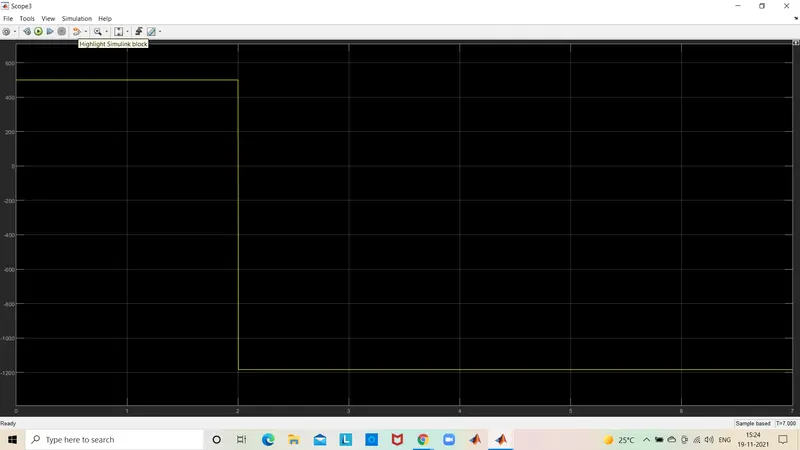
Input signals :
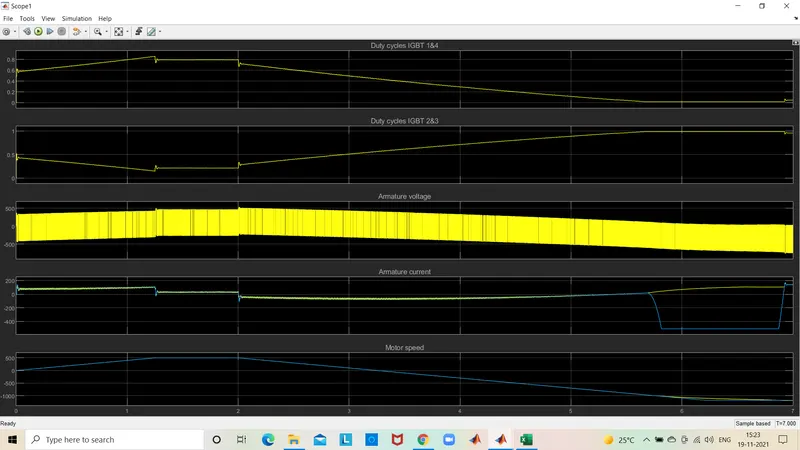
Output signals :
- Before starting the simulation, set the initial bus voltage to 515 V via the GUI block (The Initial States Setting' button and 'Cbus variable).
- Start the simulation. You can observe the motor armature voltage and current, the four IGBT pulses, and the motor speed on the scope. The current and speed references are also shown.
- The motor is coupled to a inear load, which means that the mechanical torque of the load is proportional to the speed.
- The speed reference is set at 500 rpm at t = 0s.Observe that the motor speed follows the reference ramp accurately (+400 rpm/s) and reaches steady-state around t =1.3 s.
- The armature current follows the current reference very well, with fast response time and small ripples. Notice that the current ripple frequency is 5 kHz.
- At t = 2 s, speed reference drops to -1184 rpm. The current reference decreases to reduce the electromagnetic torque and causes the motor to decelerate with the help of the load torque.
- At t = 2.2 s, the current reverses to produce a braking electromagnetic torque (dynamic braking mode). This causes the DC buS voltage to increase.
- At t = 3.25 s, the motor reaches O rpm and the load torque reverses and becomes negative. he negative current now produces an accelerating electromagnetic torque to allow the motor to follow the negative speed ramp (-400 rpm/s). At t = 6.3 s, the speed reaches -1184 rpm and stabilizes around its reference.
B : Also, Design the parameters in excel sheet.
A7 B: