Project-1: Powertrain for aircraft in runways
1] Search and list out the total weight of various types of aircrafts.
ANSWER:-
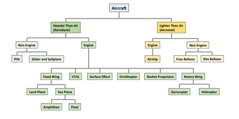
The basic classification of aircrafts is as follows
Antonov An-225
| MTOV[KG] | MLW[TONNES] |
| 640,000 | 591.7 |
AIRBUS A380-800
| MTOV[KG] | MLW[TONNES] |
| 575,000 | 394 |
BOEING 747-8F
| MTOW | MLW |
| 447,700 | 346.091 |
BOEING 747-400
| MTOW | MLW |
| 396,900 | 295.742 |
LOCKHEED L-1011-500
| MTOW | MLW |
| 231,300 | 166.92 |
Types of aircraft weights are the following:
1)Manufatures empty weight:
-It includes the weight of aircraft of the entire flight with its intergal working parts,but excludes baggage ,passenger and fuels.
2)zero fuel weight:
-It includes total weight of aeroplanes including unuseable fuels but excludes total weight of useable fuel at board.
3)Payload:
-It is load carrying capacity of an aircraft which includes passenger ,cargo and fuels,But if it is in the case of cargo flight it determines the total load of logistics weight of the container which it needs to transport.
4)Maximum take off weight:
-This is the maximum weight at which the aircraft would be made to takeoff .
5)Regulated take off weight:
-Depending on different factors (flap setting,altitude,lenght of runway),RTOW varies for each take off,but can never be high for MTOW.
6)Maximum landing weight:
-It is maximum weight at which an aircraft is permitted to land.
7)Maximum Ramp weight:
-It is the maximum weight used for manuevering (towing) aircraft on the ground.
2] Is there any difference between ground speed and air speed?
ANSWER:-
While ground speed is the airplane’s speed relative to the surface of the Earth, airspeed is its speed relative to the air it is flying in.
As mentioned above, true airspeed is simply the speed at which an aircraft is moving relative to the air it is flying in. As such, it’s also the speed at which the air is flowing around the aircraft’s wings.
Ground speed, on the other hand, is the aircraft’s speed relative to the ground. One thing that should be noted here is that it’s its horizontal rather than vertical speed – an aircraft climbing completely vertically would have a ground speed of zero.
In other words, while airspeed is what determines whether there is enough airflow around an aircraft to make it fly, ground speed is what determines how fast an aircraft will get to its destination.
3] Why is it not recommended to use aircraft engine power to move it on the ground at Airport?
ANSWER:-
High engine thrust during maintenance activity can cause considerable damage to airplanes and other elements in the airport environment. An example of this problem occurred after an airplane arrived at its final destination with a log entry indicating the flight crew had experienced anomalous engine operation. Subsequent evaluation resulted in replacement of an engine control component, followed by an engine test and trim run to verify proper engine operation. The airplane was positioned on an asphalt pad adjacent to a taxiway, with the paved surface extending from the wingtips aft to the empennage. During the high- power portion of the test run, a 20- by 20-ft (6.1- by 6.1-m) piece of the asphalt immediately aft of the engine detached and was lifted from the pad surface. This 4-in (10.2-cm)-thick piece of asphalt drifted up and into the core area of the left engine exhaust wake, where it shattered into numerous smaller pieces. The pieces were driven aft at substantial velocity, striking the aft fuselage and left outboard portion of the horizontal tail. The maintenance crew was alerted to the ramp disintegration and terminated the engine run. Subsequent inspection found that the outboard 4 ft (1.2 m) of the left horizontal stabilizer was missing, as was the entire left elevator. Corrective action included replacing the stabilizer and left elevator and repairing holes in the fuselage.
Foreign Object Damage
Foreign object damage (FOD) caused by high engine thrust can affect airport operations as it relates to
- Airplane structure.
- Flight controls.
- Equipment and personnel.
Airplane structure.
In an incident related to FOD caused by high engine thrust, Boeing was informed that a 737 had landed at a European airport and the flight crew had discovered significant damage during their walkaround inspection. Damaged areas included the right horizontal stabilizer leading edge and lower surface and elevator lower surface. Upon inspection, a piece of bricklike paving material was found embedded within the stabilizer structure. Shortly before the FOD was identified, the Boeing Field Service representative at the originating airport was notified of runway threshold damage. Subsequent correlation of these events matched the brick paving material extracted from the airplane with identical material formerly located along the runway threshold. The paving material was lifted and blown aft by the engine exhaust as the airplane turned onto the runway for takeoff (see photographs below). Repair included replacement of the stabilizer, elevator, elevator tab, and stabilizer-to-body closure panels.
Flight controls.
FOD can also affect flight control system component interaction and system displacement force, which are intimately related to properly functioning primary control surfaces. In most airplanes, the elevator is powered by independent hydraulic systems through power control units. Some airplanes offer other modes that allow manual elevator operation. In an unpowered mode, aerodynamic balance panels, linkages, and hinges interact to assist in elevator deflection against air loads. These elements must work together to ensure that actual elevator displacement is proportional (and repeatable) with respect to the control column displacement, thereby providing a consistent pitch response. This interrelationship of proportional response is sufficiently important that aviation regulatory agencies impose certification requirements prohibiting airplane response reversal and requiring airplane pitch response to be proportional to control column displacement.
Even subtle FOD to the external portions of the elevator can change the surface balance and alter the airflow characteristics in a way which may induce surface flutter. This dynamic and uncommanded movement of the surface can grow in both amplitude and frequency, causing additional damage. Portions of the surface may be destroyed by the violence of the induced motion. If this motion is great enough, it can be coupled into nearby airplane structure and cause collateral damage. In exceptional cases, control surface flutter could lead to loss of airplane control.
Equipment and personnel.
FOD also has the potential to affect the many aspects of ramp operations. These operations subject people, baggage carts, service vehicles, and airport infrastructure to injury and damage.
For example, unsecured baggage carts can be displaced by the exhaust of passing airplanes, causing airplane damage or injury to personnel (see "Foreign Object Debris and Damage Prevention" in Aero no. 1, Jan. 1998). Engine inlets represent a potential personnel ingestion hazard (see "Engine Ingestion Hazards — Update" in the Jan.-Mar. 1991 Airliner magazine). Airplane reverse-thrust operations and the use of reverse thrust to move an airplane will increase the power hazard area and require particular care to ensure that people and equipment are adequately protected.
"Taxi Operations By Maintenance Personnel" (Apr.-June 1988 Airliner magazine) discusses the increased risk of injury and damage from inadequate clearance between the airplane and surrounding objects.
4] How an aircraft is pushed to runway when its ready to take off?
ANSWER:-
There are two ways through which an aircraft is pushed to the runway on Airport.
Pushback – In aviation, pushback is an airport procedure during which an aircraft is pushed backwards away from an airport gate by external power. In aviation , pushback is an airport procedure during which an aircraft is pushed backwards away from an airport gate by external power. Pushbacks are carried out by special, low-profile vehicles called pushback tractors or tugs. Although many aircraft are capable of moving themselves backwards on the ground using reverse trust(a procedure referred to as a power back), the resulting jet blast or prop wash might cause damage to the terminal building or equipment. Engines close to the ground may also blow sand and debris forward and then suck them into the engine, causing damage to the engine. A pushback is therefore the preferred method to move the aircraft away from the gate.
Pushbacks at busy aerodomes are usually subject to ground control clearance to facilitate ground movement on taxiways. Once clearance is obtained, the pilot will communicate with the tractor driver (or a ground handler walking alongside the aircraft in some cases) to start the pushback. To communicate, a headset may be connected near the nose gear. Since the pilots cannot see what is behind the aircraft, steering is done by the pushback tractor driver and not by the pilots. Depending on the aircraft type and airline procedure, a bypass pin may be temporarily installed into the nose gear to disconnect it from the aircraft's normal steering mechanism. Once the pushback is completed, the tow bar is disconnected, and any bypass pin removed. The ground handler will show the bypass pin to the pilots to make it clear that it has been removed. The pushback is then complete, and the aircraft can taxi forward under its own power. Pushbacks are carried out by special, low-profile vehicles called pushback tractors or tugs. Although many aircraft are capable of moving themselves backwards on the ground using reverse thrust (a procedure referred to as a power back), the resulting jet blast or prop wash might cause damage to the terminal building or equipment. Engines close to the ground may also blow sand and debris forward and then suck them into the engine, causing damage to the engine. A pushback is therefore the preferred method to move the aircraft away from the gate. Closer to departure, an aircraft tug will park right in front of the nose wheel. The tug might be directly attached to the plane's nose gear with a tow bar, or could be a wheel-lift tug. These tugs cradle the nose gear, then lift it up before moving the plane. That gives the tug driver control over the plane's direction during pushback. New taxi technologies are appearing, like pilot-controlled tugs, and electric motors mounted to the plane's landing gear. Both promise to save fuel, and reduce airport noise. When the aircraft is stopped, the brakes of the towing vehicle alone should not be relied upon to stop the aircraft. The man in the cockpit should coordinate the use of the aircraft brakes with those of the towing vehicle.
Taxiing is the movement of an aircraft on the ground, under its own power, in contrast to towing or push-back where the aircraft is moved by a tug. The aircraft usually moves on wheels, but the term also includes aircraft with skis or floats for water-based travel. An airplane uses taxiways to taxi from one place on an airport to another; for example, when moving from a hangar to the runway. The term taxiing is not used for the accelerating run along a runway prior to take-off, or the decelerating run immediately after landing, which is called the take-off roll and landing rollout, respectively. When taxiing, aircraft travel slowly. This ensures that they can be stopped quickly and do not risk wheel damage on larger aircraft if they accidentally turn off the paved surface. Taxi speeds are typically 30 to 35 km/h.
Taxiing (rarely spelled taxying) is the movement of an aircraft on the ground, under its own power, in contrast to towing or pushback where the aircraft is moved by a tug. The aircraft usually moves on wheels, but the term also includes aircraft with skis or floats (for water-based travel). An airplane uses taxiways to taxi from one place on an airport to another; for example, when moving from a hangar to the runway. The term "taxiing" is not used for the accelerating run along a runway prior to take-off, or the decelerating run immediately after landing, which are called the take-off roll and landing rollout, respectively. The thrust to propel the aircraft forward comes from its propellers or jet engines. Reverse thrust for backing up can be generated by thrust reversal such as on the Boeing C17 Globe master III, or reversible pitch propellers such as on the Lockheed C130 Hercules, a procedure known as power back. Most aircraft, however, are not designed to back up on their own and must be pushed back either by hand or by using an aircraft tug. At low power settings, combustion aircraft engines operate at lower efficiency than at cruise power settings. A typical A320 spends an average of 3.5 hours a day taxiing, using 600 litters (160 U.S. gal) of fuel. Hybrid electrically driven nose gear are under development to allow high use aircraft to shut down the engines during taxi operations. Steering is achieved by turning a nose wheel or tail wheel/rudder; the pilot controls the direction travelled with their feet. Larger jet aircraft have a tiller wheel on the left side of the cockpit that acts as a steering wheel allowing the nose wheel to be turned hydraulically. Braking is controlled by differential toe or heel brakes. Not all aircraft have steerable wheels, and in some cases steering is solely by means of differential braking (all Van's Aircraft for instance) or solely by means of the rudder (including all floatplanes).
5] Learn about take off power, tyre design, rolling resistance, tyre pressure, brake forces when landing.
ANSWER:-
Takeoff is the phase of flight in which an aerospace vehicle leaves the ground and becomes airborne.
For aircraft that take off horizontally, this usually involves starting with a transition from moving along the ground on a runway. For balloons, helicopters, and some specialized fixed-wing aircraft (VTOL aircraft such as the Harrier), no runway is needed. Takeoff is the opposite of landing.
Take off performance can be predicted using a simple measure of the acceleration of the aircraft along the runway based on force equilibrium.
The forces involved will be,
T – Thrust of propulsion system pushing aircraft along runway.
D – Aerodynamic Drag of vehicle resisting the aircraft motion.
F – Rolling resistance friction due to the contact of wheels or skids on the ground.
During take-off run the imbalance in these forces will produce an acceleration along the runway.
dVdt=T-D-Fm">dVdt=T−D−FmdVdt=T-D-Fm
where dV/dt is the acceleration along the runway and m is the mass of the vehicle.
The procedure for take-off will be that the vehicle will accelerate until it reaches a safe initial flying speed. The pilot can then rotate the vehicle to an attitude to produce climb lift and it will ascend from the ground. The determination of this safe flying speed or rotation speed, VR, is a critical factor in determining take-off performance.
Take-off rules vary slightly depending on the aircraft category. Small commuter aircraft should be considered as meeting FAR 23 rules, transport category aircraft should comply with FAR 25 rules.
Small commuter aircraft :
For safety reasons VR is usually determined as being 1.1 × VSTALL or 1.05 × VMIN CONTROL
which ever is greater. Stall speed, VSTALL, is the lowest speed that the aircraft can be flown before the airflow starts to separate from wings as the angle of attack becomes too great. The wing is assumed in this case to be in take-off configuration or "clean".
It can be calculated based on knowledge of the aircraft take-off configuration and hence the maximum achievable lift coefficient CL(max). As shown in the previous section , to maintain level flight the lift produced must equal the weight, hence the stall speed can be calculated as,
Vstall=W12CL(max)ρS">Vstall=√W12CL(max)ρSVstall=W12CL(max)ρS
Minimum control speed, VMC is a more complex calculation and requires knowledge of the stall characteristics of the tailplane and elevator. For conventional aircraft there is only a small difference between VR calculations based on stall speed or minimum control speed.
V1- Abort decision speed. Below this speed the take-off can be safely aborted. After this there will not be sufficient runway length to allow the aircraft to decelerate to a stop.
V2 – Safe climb speed. V2 must be no less than 1.2 * Vstall. Below this speed aircraft cannot attain sufficient climb rate.
Transport Aircraft :
VR must not be less than V1
VR must be greater than 1.05 * VMC
VR must be set so that aircraft achieves V2 before reaching a height of 35ft above the runway surface.
Aircraft must climb at a minimum gradient to avoid obstacles at the end of the runway. With engine failure on multi-engined aircraft, this speed should still be achievable.
Thrust:
The thrust of gas turbine or turbofan engines will be relatively constant during take-off. A good assumption is to use the manufacturer's values for maximum static thrust for take-off calculations.
T=Pshaft×ηV">T=Pshaft×ηVT=Pshaft×ηV
It is critical to correctly estimate the propeller efficiency for the particular aircraft velocity along the runway. At V=0 the efficiency is 0 so the above equation makes no sense. At V=VR the efficiency will be in the range 50% to 80% depending on the type of propeller system used and the thrust value at this point will be easy to obtain. In practice, the thrust obtained throughout the take-off roll is roughly constant so this end point value is a good approximation from V=0 to V=VR.
Drag:
The resistance to motion due to the air viscosity will give a drag of
D=12⋅Cd⋅ρ⋅A⋅V2">D=12⋅Cd⋅ρ⋅A⋅V2D=12⋅Cd⋅ρ⋅A⋅V2
where CD can be considered constant,
Although Drag Coefficient is constant, Drag will increase in proportion to the square of velocity.
Rolling Resistance:
The friction between aircraft and runway will be proportional to the normal force exerted by the aircraft on the runway.
F=μ(W-L)">F=μ(W−L)F=μ(W-L)
The normal force will be the difference between Weight of aircraft and Lift, the friction coefficient will be typically of a magnitude of 0.02 for a standard tarmac runway.
The rate of change of velocity can be predicted at any point on the take-off roll by substituting results for T, D and F into the initial equation for dV/dt. The subsequent velocity at any point can be found by integrating this resulting equation and the distance traveled found by then integrating the velocity.
Typically acceleration will be dominated by the drag component as thrust, weight and friction are relatively constant during this period. This leads to the result shown where acceleration is inversely proportional to velocity squared.
Due to the quadratic nature of acceleration change, an average value, (dVdt)avg=a">(dVdt)avg=a(dVdt)avg=a can be used for the take-off run. This average acceleration can be found at the point where,
V=VR2">V=VR√2V=VR2
This average acceleration can be used to simplify calculations and the take-off run can be calculated as an equivalent constant acceleration over the complete period of time (tR) taken to get from 0 to VR. For a constant acceleration take-off calculation.
VR=a.t">VR=a.tVR=a.t and distance travelled , s=12at2">s=12at2s=12at2
Rearranging leads to a relatively simple calculation to predict distance to rotation point.
s1=12VR2a">s1=12V2Ras1=12VR2a
From the rotation point, the end of the runway can be defined by the requirement to clear a 35ft obstacle at the end. During rotation it can be assumed that any residual excess thrust is absorbed in overcoming the lift induced drag as the aircraft begins to climb. Acceleration reduces and a constant flight speed during this climb phase can be assumed. The distance along the ground from rotation point to obstacle clearance point with thus be,
s2=35tanθ">s2=35tanθs2=35tanθ ft,
Take-off (Balanced) Field Length:
The required length of runway will be the sum of the distance required to get to rotation speed and the extra length required to clear a 50ft obstacle or the extra length required to allow for rapid braking if the pilot decides to abort take-off at the decision speed V1.
This length will typically be considerably longer than the distance required to achieve rotation (flying) speed. A rough approximation is that runway total length is around 2 x s1
Distance to V1 can be calculated in a manner similar to that shown for VR. The calculation of braking distance will require knowledge of the maximum braking friction coefficient that can be generated by the aircraft. This information should be available from manufacturer's data. Braking distance calculations should also be done without any assumption of reverse thrust from engines as during a take-off abort, engine power may not be available.
Landing:
The landing run can be calculated in a similar fashion to the take off distance. The aim is again to minimise the distance.
The touch down velocity should be approximately the stall speed of the aircraft in landing configuration. This will be achieved by a pitch manoeuvre during the flare portion of the approach which which increase drag an decelerate the aircraft to minimum flying speed.
The deceleration on the landing roll from VTD to V0 will be accomplished by braking and reverse thrust. This can be solved by the average acceleration approach that was used to estimate the take-off roll.
dVdt=-T-D-Fm">dVdt=−T−D−FmdVdt=-T-D-Fm
The negative acceleration or deceleration value will be based on friction coefficient for maximum braking and the value of reverse thrust (if available).
Braking force:
Stopping an aircraft landing at 180-200 mph requires a lot of braking force. To do this, the aircraft has brake unit on each of the wheels on the maingear assembly. On landing, pilots should use aerodynamic braking by applying extra back-pressure on the stick or yoke. Extreme caution should be used whenapplying brakes at any signicant speed, and only when the end of the runway is quickly approaching. Never step on the brakes to make a runway exit. Applyingthe brakes at too high a speed could burn the tires, wear out the brakes, or result in a ground loop or swerve.
Aircraft Disc Brake:
In the landing gear it is used to brake the wheels while touching the ground. These brakes are operated hydraulically. In most modernaircraft they are activated by the top section of the rudder pedals ("toe brakes"). In some older aircraft the bottom section is used instead ("heel brakes"). Leversare used in a few aircraft. Most aircraft are capable of differential braking.
In addition to the brakes, there are two other systems which help slow the aircraft down on landing. The spoilers and the reverse thrust.
Spoilers
Have you noticed the large panels on the top of the wings raise up on touch down? These are the called the spoilers as they literally spoil the airflow over the wing. This dumps any remaining lift the wings are generating, allowing the wheels to take all the weight and achieve maximum efficiency from the brakes.
Reverse thrust
The final part of the braking process comes from reverse thrust. Just after we have touched down, we pull two levers on top of the thrust levers to engage the reverse thrust, a sort of “reverse gear” for jet engines.
There are two stages of reverse thrust — idle reverse and max reverse. Idle reverse is used on most landings and max reverse is used when the landing performance requires it, normally when the aircraft is landing at hot or high elevation airfields.
This forward directed airflow helps slow the aircraft down but is most efficient at high speeds. If using max reverse, we drop this down to idle reverse at 60 knots (70 mph) and then back to normal thrust as we vacate the runway at around 20 knots (25 mph).
Design and construction of the Aircraft tyre:
When it comes to safety, tyres are one of the most important components of aircraft. They help to absorb the shock of landing and provide cushioning. It also provides the necessary traction for braking and stopping of an aircraft.
An aircraft tyre is designed to withstand extremely heavy loads while landing, take off, taxing, and parking. The number of wheels required for aircraft increases with the weight of the aircraft, as the weight of the aeroplane needs to be distributed more evenly.
A Boeing 737NG & 737MAX uses 6 wheels, Boeing 787 uses 10 wheels, Boeing 777 uses 14 wheels and Airbus A380 uses 22 wheels. Aircraft tyres work under extreme conditions, carrying up to 340 tons and accelerating at over 250 km/hour at takeoff, in addition to enduring varied environmental stress when in flight and taxiing.
Carcass plies are used to form the tire. They are sometimes called casing plies. An aircraft tyre is constructed for the purpose it serves.
- They support the weight of an aircraft while it is on the ground.
- It also provides the necessary traction for braking and stopping of an aeroplane.
- Tyre also helps to absorb the shock of landing and provide cushioning the roughness of takeoff, roll-out, and taxi operations.
Unlike an automobile or truck tyre, it does not have to carry a load for a long period of continuous operation. However, an aircraft tyre absorbs the high impact loads of landing, and also it’s operating at high speeds for a short time when required.
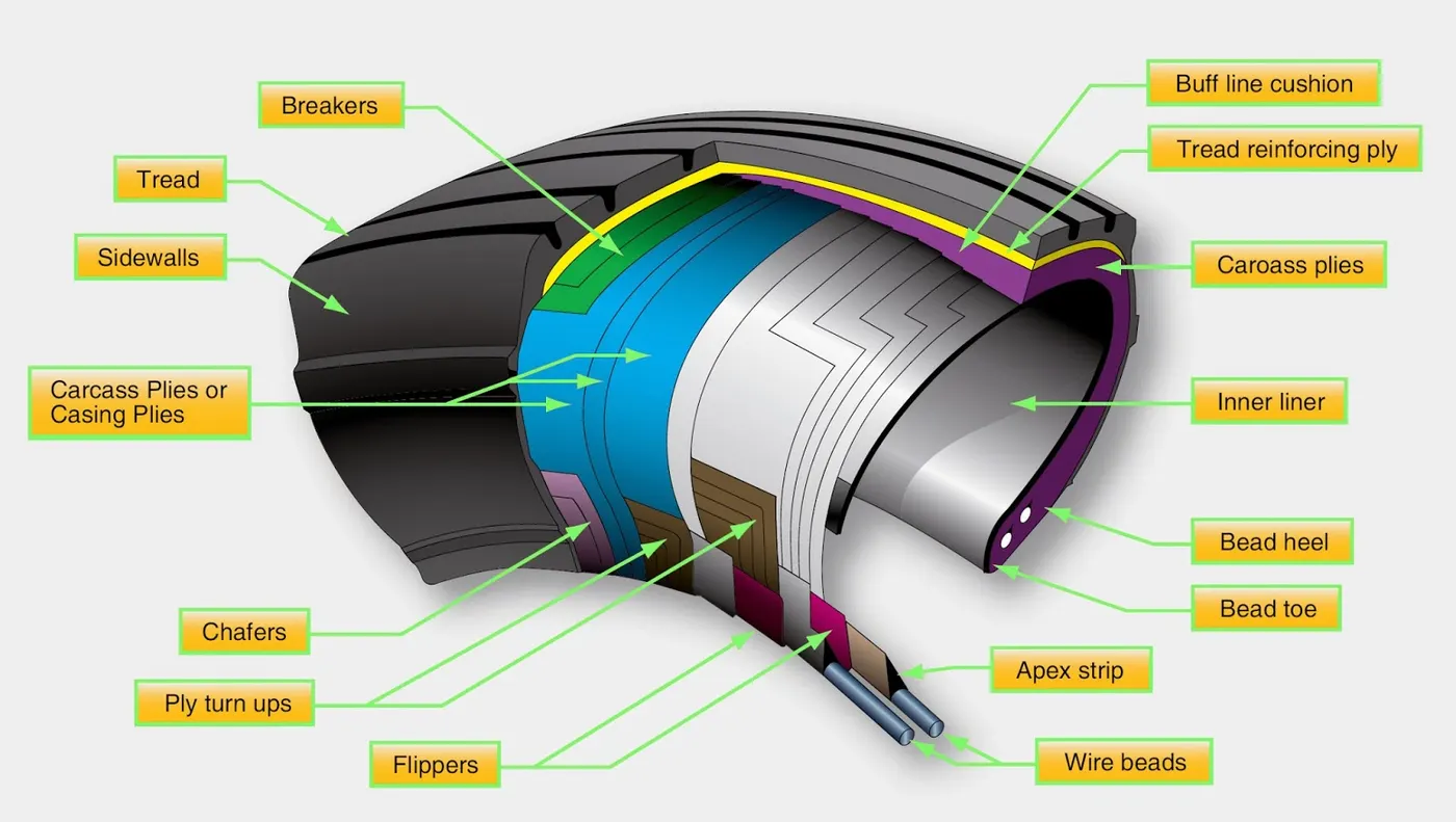
Retreading – Retreading is methods of restoring a worn tyre by renewing the tread area or by renewing the tread area plus one or both sidewalls. Repairs are included in the tyre retreading process.
Load Rating – Load rating is the maximum permissible load at a specified inflation pressure.
Ply Rating – Ply Rating is used to identify the maximum recommended load rating and inflation pressure for a specified tyre. It is an index of tyre strength.
Speed Rating – The speed rating is the maximum takeoff speed to which the tyre has been tested.
Skid Depth – Skid depth is the distance between the tread surface and the deepest groove as measured in the mould.
Aircraft tyres must have an approved speed and load rating and have sufficient clearance when retracted through landing gear to allow for tyre growth. Tyre growth is the increase in the size of the tyre due to centrifugal forces at high speed.
Aircraft tyres may be Tube-type or Tubeless
Tubeless tyres are more advantageous over tube-type. There is no longer the use of tube-type tyre in recent aviation. Nowadays all airliners are using tubeless tyres. Tubeless that are meant to be used without a tube has the word TUBELESS on the sidewall of the tyre.
6] With necessary assumptions, calculate the force and power required to push / pull an aircraft by a towing vehicle.
ANSWER:-
The force propelling the vehicle forward, has to accomplish
the following:
• overcome the rolling resistance;
• overcome the aerodynamic drag;
• provide the force needed to overcome the component of the vehicle’s weight acting down the slope
• accelerate the vehicle, if the velocity is not constant.
Rolling Resistance Force (Frr)→ The rolling resistance due to the friction of the vehicle tyre on the road. Friction in bearings and the gearing system also play their part. The rolling resistance is approximately constant, and hardly depends on vehicle speed. It is proportional to vehicle weight. The equation is:
Frr=μrrmg
where μrr→coefficient of rolling resistance
Aerodynamic Drag Force (Frr)→→This part of the force is due to the friction of the vehicle body moving through the air. It is a function of the frontal area, shape, protrusions such as side mirrors, ducts and air passages, spoilers, and many other factors. The formula for this component is:
Fad=(1/2)(ρACD(V^2))
where ρ→density of air, A→frontal area, CD→coffecient of drag, V→velocity.
Hill Climbing Force (FhcFhc)→→The force needed to drive the vehicle up a slope. It is simply the component of the vehicle weight that acts along the slope.The equation is:-
FHC=mgsin(ψ)
FTE=Frr+Fad+Fhc+Fla+Fωa
calculations:-
To calculate rolling resistance force:-
Assume for Airbus-A380
Aircraft payload = 575000 kilos
Towing car mass = 50000 kilos
Coefficient of rolling resistance = 0.013
There for rolling resistance force is 79706.25N
To calculate drag force:-
Air density = 1.225 Kg/m^3
Width = 7.12m
Height = 21.25m
Frontal Area = 151.3 m^2
Drag coefficient of towing vehicle = 0.5
Drag coefficient of Aircraft = 0.09
Speed = 2.78 m/s
Drag force = 64.45804 N
Total Force = 79770.7080 N
7] Design an electric powertrain with type of motor, it’s power rating, and energy requirement to fulfill aircraft towing application. Estimate the duty cycle range to control the aircraft speed from zero to highest. Make all required assumptions. Prepare a table of assumed parameters. Draw a block diagram of powertrain.
ANSWER:-
| Assumption For Powertrain Design | |
| Aircraft Mass (kg) | 575,000 kg |
| Towing Vehicle mass (kg) | 50,000 kg |
| Rolling Resistance Co-efficient | 0.013 |
| Air Density | 1.225 kg/m3 |
| Towing Vehicle Drag Co-efficient | 0.5 |
| Aircraft Drag Co-efficient | 0.09 |
| Frontal area | 20 m2 |
| Inclination angle | 0 rad |
| Tyre Pressure | 203 PSI/14 bar |
| Towing Velocity(V) | 10 km/h = 2.778 m/s |
| Towing Time(t) | 2 min |
| Radius of the towing vehicle wheel |
0.38 m |
Traction force(F) quantity that is =
| 79770.70804 N |
Required Power =
| 221.7625684 kW |
Required Torque = F x r.
T = 79770.7 x 0.38 = 30,312.87 N-m
Energy, E = P x t.
E = 221.76 x 2 x 60/3600 = 7.4 kWh