Project
AIM: To study the simulation of BAJA ATV
EXPLANATION: CVT is Continuously variable transmission and it is an automatic transmission that can change seamlessly through a continious range of gear ratios. The most common type of CVT isa pulley and belt driven one. It usses a V-belt which runs between two variable diameter pulleys. The pulleys consist of two cone-shaped halves,so the effective diameter of the pulley is dependent on the distance between the two-halves of the pulley.The V-shaped cross section of the belt causes it to ride higher on one pulley and lower on the other, therefore the gear ratio is adjusted by moving the two sheaves of one pulley closer together and the two sheaves of the other pulley farther apart.
The pulley-radial thickness of the belt is a compromise between maximum gear ratio and torque. Steel reinforced v-belts are sufficient for low-mass low-torque applications like utility vehicles and snowmobiles but higher mass and torque applications such as automobiles require a chain. Each element of the chain must have conical sides that fit the pulley when the belt is running on the outermost radius. As the chain moves into the pulleys the contact area gets smaller. As the contact area is proportional to the number of elements, chain belts require many very small elements.
Study 1: CVT Model:-
The BAJA CVT ATV model consists of a Signal builder block, Engine block, Engine sensors, Vehicle transmission, Vehicle body, Tyres and Solver configuration block as seen in Fig1. The vehicle weighs about 250 Kilos has 2 axels that connect to 4 wheels. The idle speed of the engine is set at 2100 RPM and the pulley is set at 0.8 and 0.7.
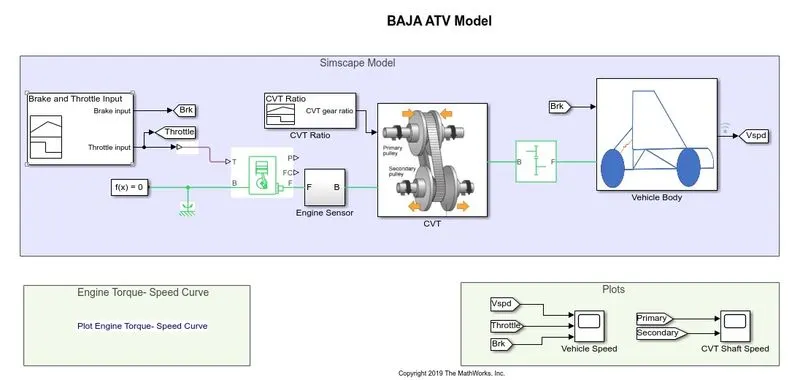
Fig1
The CVT has some sub-blocks like transmission, input and output shaft inertia and motion sensors. The Brake and throotle input is seen in fig2. The signal builder block is used to set up the brake input signal and the throotle input signal. The throttle is given as 0.3 for the first 20 seconds and it increases to 1 for the rest of the simulation. The throttle valve is used to control the amount of Air and Fuel entering into the engine.
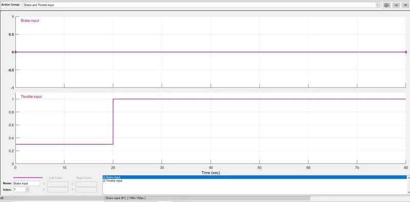
Fig2
Engine torque-speed curve is seen in Fig3. Following figure shows the torque output wrt engine RPM.
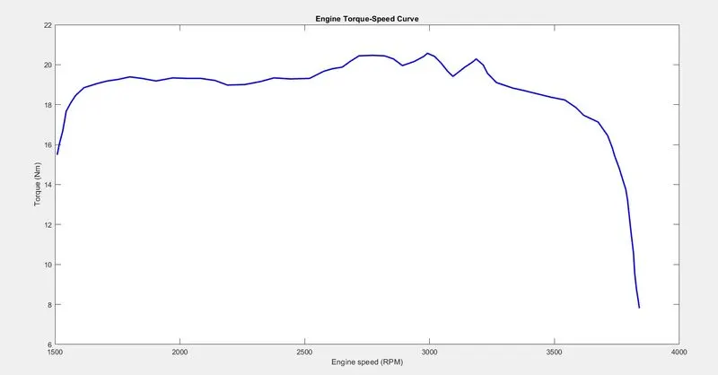
Fig3
Fig4 shows CVT Gear Ratio. The gear ratio is maintained for 5 seconds with a value of 2.3 and then it linearly decreases to 1.8 and maintained constant for overall simulation.
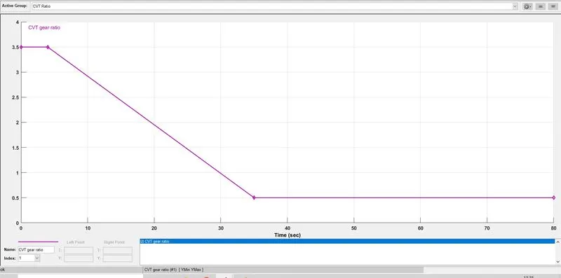
Fig4
Following figure shows CVT sub-block
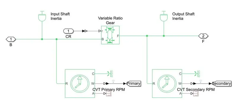
Fig5
Following fig 6 shows vehicle body sub-block. Vehicle body subblock consists of 4 wheels connected by 2 axels. It also consists of dual shoe Brake. And a vehicle body that has a weight of 250 kilos.
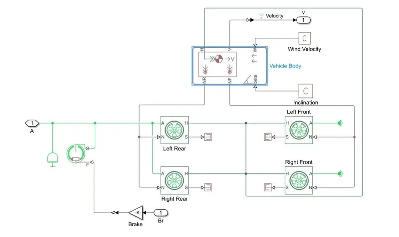
Fig6
Study 2: CVT Model With Dashboard:-
Following Fig shows BAJA ATV CVT Dashboard
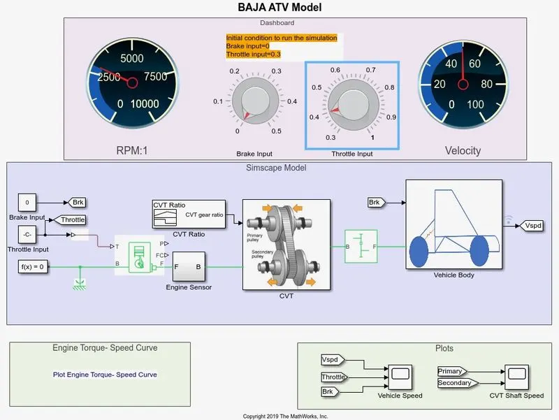
Fig7
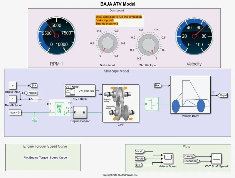
Fig8
The two figures above shows the ATV runnining and the Dashboard model which consists of two meters that is for engine RPM and Speed and two dials , one of which is used for throttle and the other to simulate brake force applied. As we increase the throttle the CVT gear ratio is varied and the engine rpms rise fromm an idle of 2500 RPM to 3750 RPM. i.e. the throttle input is changed fro 0.3 to 1. If we roll off the throttle then the RPM drops. Simillarly as we increse the braking in the ATV using the brake knob the RPM drops even more and finally become 0 if we apply max brake force.