Project-1: Powertrain for aircraft in runways
Tasks
- Search and list out the total weight of various types of aircraft.
- Is there any difference between ground speed and airspeed?
- Why is it not recommended to use aircraft engine power to move it on the ground at the Airport?
- How an aircraft is pushed to the runway when it's ready to take off?
- Learn about take-off power, tyre design, rolling resistance, tyre pressure, brake forces when landing.
- With necessary assumptions, calculate the force and power required to push/pull an aircraft by a towing vehicle.
- Design an electric powertrain with the type of motor, its power rating, and energy required to fulfil aircraft towing application. Estimate the duty cycle range to control the aircraft speed from zero to highest. Make all required assumptions. Prepare a table of assumed parameters. Draw a block diagram of the powertrain.
Task 1
Search and list out the total weight of various types of aircraft.
The different terms represent different weights or masses. For each flight, the weights are taken into account for various reasons.
Manufacturer's Empty Weight (MEW)
Also called Manufacturer's Weight Empty (MWE) or Licensed Weight. It is the weight of the aircraft "as-built" and includes the weight of the structure, power plant, furnishings, installations, systems and other equipment that are supposed an integral part of an aircraft. This excludes any baggage, passengers, or usable fuel.
Zero Fuel Weight (ZFW)
This is the total weight of the aeroplane and all its contents (including unusable fuel), but excluding the total weight of the usable fuel on board. As a flight progresses and fuel is consumed, the total weight of the aeroplane reduces, but the ZFW remains constant. Maximum zero fuel weight (MZFW) is the maximum weight allowed before usable fuel and other specified usable agents (engine injection fluid, and other consumable propulsion agents) are loaded.
Operating Empty Weight (OEW)
It is the basic weight of an aircraft including the crew, all fluids necessary for operation such as engine oil, engine coolant, water, unusable fuel and all operator items and equipment required for flight but excluding usable fuel and the payload.
Payload
It is the carrying capacity of an aircraft. It includes cargo, people, extra fuel. In the case of a commercial airliner, it may refer only to revenue-generating cargo or paying passengers.
Maximum Takeoff Weight (MTOW)
This is the maximum weight at which the pilot of the aircraft is allowed to attempt to take off.
Regulated Takeoff Weight (RTOW)
Depending on different factors (e.g. flap setting, altitude, air temperature, length of runway), RTOW or maximum permissible takeoff weight varies for each takeoff. It can never be higher than MTOW.
Maximum Landing Weight (MLW)
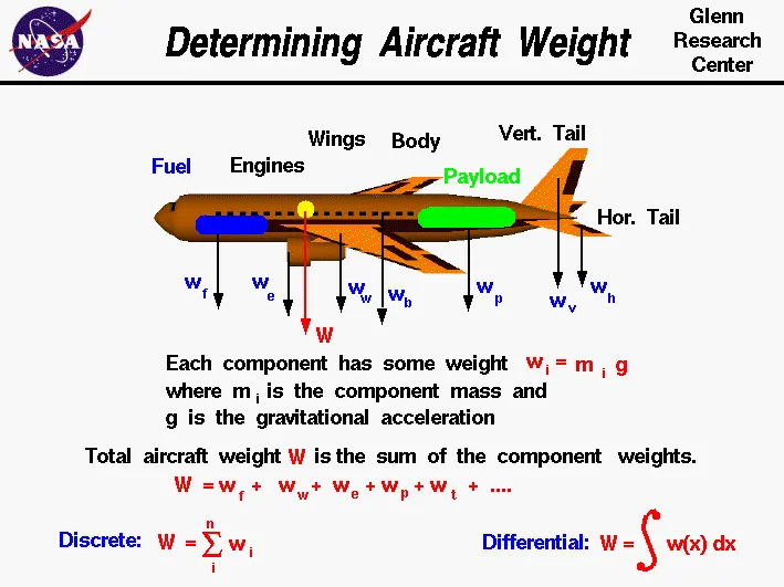
This maximum weight at which an aircraft is permitted to land. The following image depicts takeoff weight components.
Maximum Ramp Weight (MRW)
Its also called maximum taxi weight (MTW). It is the maximum weight authorized for manoeuvring (taxiing or towing) an aircraft on the ground.
Aircraft Gross Weight
It is the total aircraft weight at any moment during the flight or ground operation. This decreases during the flight due to fuel and oil consumption.
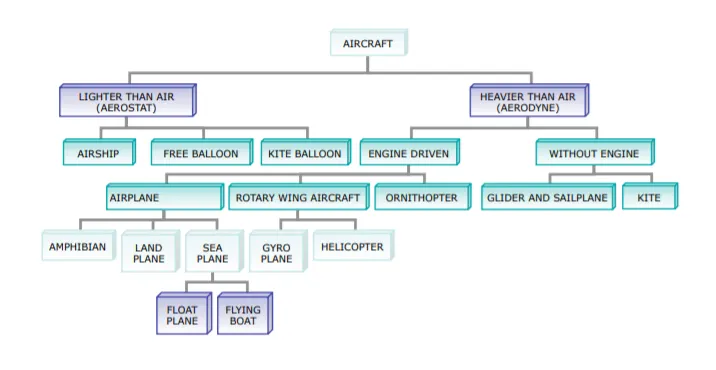
Types of Aircraft
|
Airbus { A300, A310, A318, A319, A320,
|
Boeing
|
Single-Engine Piston
|
|
Business Jets
|
Tricycle Gear
|
Taildraggers
|
|
Helicopters
|
Tiltrotors |
Light-Sport Aircraft
|
|
Turboprops |
Floatplanes or Seaplanes
|
Biplanes |
|
Kitbuilts or Homebuilts |
Airship
|
Task 2
Is there any difference between ground speed and airspeed?
Ground speed
It is when you are measuring the horizontal velocity of the plane relative to the ground. It’s the speed that is shown on the speedometer of a car. If your car quickly started levitating for God knows what reason, the speedometer reading would not take into account your vertical velocity, so a plane could be moving vertically but still have zero ground speed. It is the velocity you have in any direction perpendicular to the vertical axis.
Airspeed
It is the velocity of the plane relative to the winds around it. It is like having two cars, one travelling at 100 km/h and the other at 60 km/h, both towards the right. These speeds are the ground speeds of the car. The airspeed is wanting to know the difference in velocity between the two cars, which is 40 km/h, or -40 km/h depending on which car you are looking at. If the 100 km/h car represents the plane, and the 60 one the winds, then the difference is 40km/h. So you are essentially measuring how fast the plane is compared to the winds. And in the example above, if the car was travelling at 60 km/h to the left instead, the speed difference would be 160 km/h. It is the same thing for planes: when winds blow towards the plane, the plane’s airspeed is bigger than the ground speed, because you are adding to the ground speed, and when winds blow in the same direction as the plane, the airspeed is less than the ground speed.
In more technical terms, "ground speed is the velocity of the plane relative to a reference point on the ground. Wind speed is the velocity of wind concerning that same reference point, and airspeed is the velocity of the plane relative to that wind. Thus the airspeed is defined as the vector difference between the ground speed and the wind speed. Also note that for whatever reason, the three quantities have both direction and magnitude; they are vectors despite their names".
Now the reason why ground speed is important is that it lets you know how quickly you could reach your destination, in the same way, that the speed of a car lets you know that. The airspeed is important because it is what allows the plane to fly. The Bernoulli principle states that if a fluid like air increases its speed, then its pressure will decrease. For a plane, the plane’s wings will affect the way air flows above and below them, which will cause a pressure difference and thus cause a force, known as the lift force which is what makes the plane fly. The way the wings affect the airflow is determined by how quickly the plane is moving relative to the air, which is the airspeed.
Task 3
Why is it not recommended to use aircraft engine power to move it on the ground at the Airport?
Although most aircraft are capable of moving themselves on the ground, it is not typically done due to the following reasons,
- The jet blast from the engines can damage the terminal building and nearby equipment. It can even throw away people standing nearby.
- Engines can blow sand and debris.
- Engines can suck in sand and debris which can cause serious damage to the engine.
- It is easier for the truck driver to see the surroundings better than the pilot sitting in the cockpit with limited windows.
- The pushback truck driver knows the airport better than the pilot.
- The plane engines are very loud. This noise can add up substantially when multiple planes are moving around the airport. It won't be a pleasant experience for people sitting inside the terminal, as most people don't even like the sound of powerful motor-bikes.
- It saves fuel.
- Modern planes are huge. It is difficult to navigate such gigantic structures through limited space. An A380 is eight stories high. The pilots won't be able to see anything directly in front of them or anything behind the wings.
Actually, Pushback is for moving the aircraft backwards from the gate, and towing or taxing is the procedure to move the aircraft. These machineries are called aircraft tugs. Aircraft tugs are real modern marvels, moving aircraft weigh hundreds of tons all day, every day. A true pushback tug aims to allow the operator to have excellent visibility of the attaching mechanism between aeroplane and tug.
while moving the aircraft in the reverse direction by applying the forward thrust, care must be taken because the reverse thrust is unsafe when stopped or at low speed. This is because the nose may lift, dropping the tail on to the Tarmac. The cause is the engines being at some considerable height from the ground and the aircraft centre of gravity being just ahead of the main (rear) wheelset. Additionally, once moving backwards, if the aircraft’s own brakes are used, the same can happen, i.e., the plane can sit on its tail.
Task 4
How an aircraft is pushed to the runway when it's ready to take off?
Aircraft are usually ‘pushed’ by ground vehicles known as tow vehicles such as tow trucks. It is used mainly to reverse an aeroplane from the terminal area until it is in a position to move by itself. These tow trucks will only help move the aircraft to an area where the pilots can safely switch on the engines, not the runway! (Ground vehicles are rarely allowed to move on a runway (save for emergencies and inspection), and the aircraft is supposed to move to the runway by itself.
Aircraft don’t have powered wheels, and hence cannot move in reverse (let alone forward by themselves). Imagine a tiny jet strapped to one of your toy cars; that’s essentially how aeroplanes work on the ground! They go where the engines push them towards. (Note: There is a mechanism known as reverse thrusters, which allow the engine airflow to be pushed towards the front, but that is a highly risky manoeuvre and is only used to reduce speed immediately after landing.)
Another reason to push back an aircraft to a safe area is for safety reasons. The engines produce tremendous thrust from the exit, and an immense vacuum from the front; enough to suck in people, small vehicles, ground equipment etc. Hence it is a common procedure to start the engines once it is cleared away from the terminal area and lined up on a taxiway (roads that lead to the runway).
Task 5
Learn about taking off the power, tyre design, rolling resistance, tyre pressure, brake forces when landing.
Takeoff
It is the phase of flight in which an aircraft goes through a transition from moving along the ground (taxiing) to flying in the air, usually starting on a runway. Take off power can be predicted using a simple measure of the acceleration of the aircraft along the runway based on force equilibrium.
The forces involved will be,
T → Thrust of propulsion system pushing aircraft along the runway.
D → Aerodynamic Drag of vehicle resisting the aircraft motion.
F → Rolling resistance friction due to the contact of wheels or skids on the ground.
During the take-off run, the imbalance in these forces will produce an acceleration along the runway.
m*(dv/dt)=T-D-F
where, dv/dt is the acceleration along the runway and m is the mass of the vehicle.
The procedure for take-off will be that the vehicle will accelerate until it reaches a safe initial flying speed. The pilot can then rotate the vehicle to an attitude to produce a climb lift and it will ascend from the ground. The determination of this safe flying speed or rotation speed, Vr is a critical factor in determining take-off performance. Take-off rules vary slightly depending on the aircraft category.
For Small commuter aircraft
Vr=1.1×VSTALL
or
Vr=1.05×VControl
whichever is great.
`VSTALL = sqrt (W/(0.5* CLmax ⋅ ρ ⋅ S)`,
where S →displacement
Takeoff Field Length
The required length of the runway will be the sum of the distance required to get to rotation speed and the extra length required to clear a 50ft obstacle or the extra length required to allow for rapid braking if the pilot decides to abort take-off at the decision speed V1.
This length will typically be considerably longer than the distance required to achieve rotation (flying) speed. A rough approximation is that the runway total length is around S1=2.
Therefore,
Takeoff power = force * displacement
= (m⋅dv/dt)⋅2⋅S1=(T-D-F)⋅S1
Rolling Resistance
The friction between aircraft and runway will be proportional to the normal force exerted by the aircraft on the runway.
F=μ(W−L)
The normal force will be the difference between the Weight of the aircraft and the Lift, the friction coefficient will be typical of a magnitude of 0.02 for a standard runway
Braking Forces in Landing
The landing run can be calculated similarly to the take-off distance. The aim is again to minimise the distance.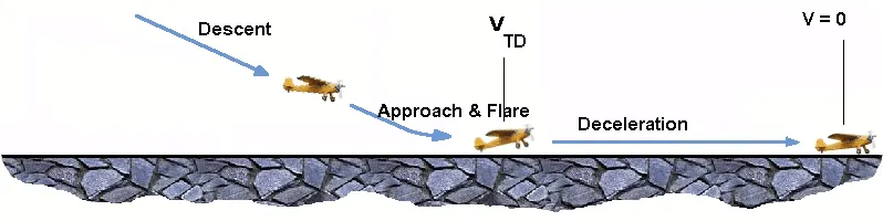
The touchdown velocity should be approximately the stall speed of the aircraft in the landing configuration. This will be achieved by a pitch manoeuvre during the flare portion of the approach which increases drag and decelerates the aircraft to minimum flying speed. The deceleration on the landing roll from VTD to V0 will be accomplished by braking and reverse thrust. This can be solved by the average acceleration approach that was used to estimate the take-off roll.
m⋅(dv/dt)= -T-D-F
The negative acceleration or deceleration value will be based on the friction coefficient for maximum braking and the value of reverse thrust.
Aircraft Tyre design
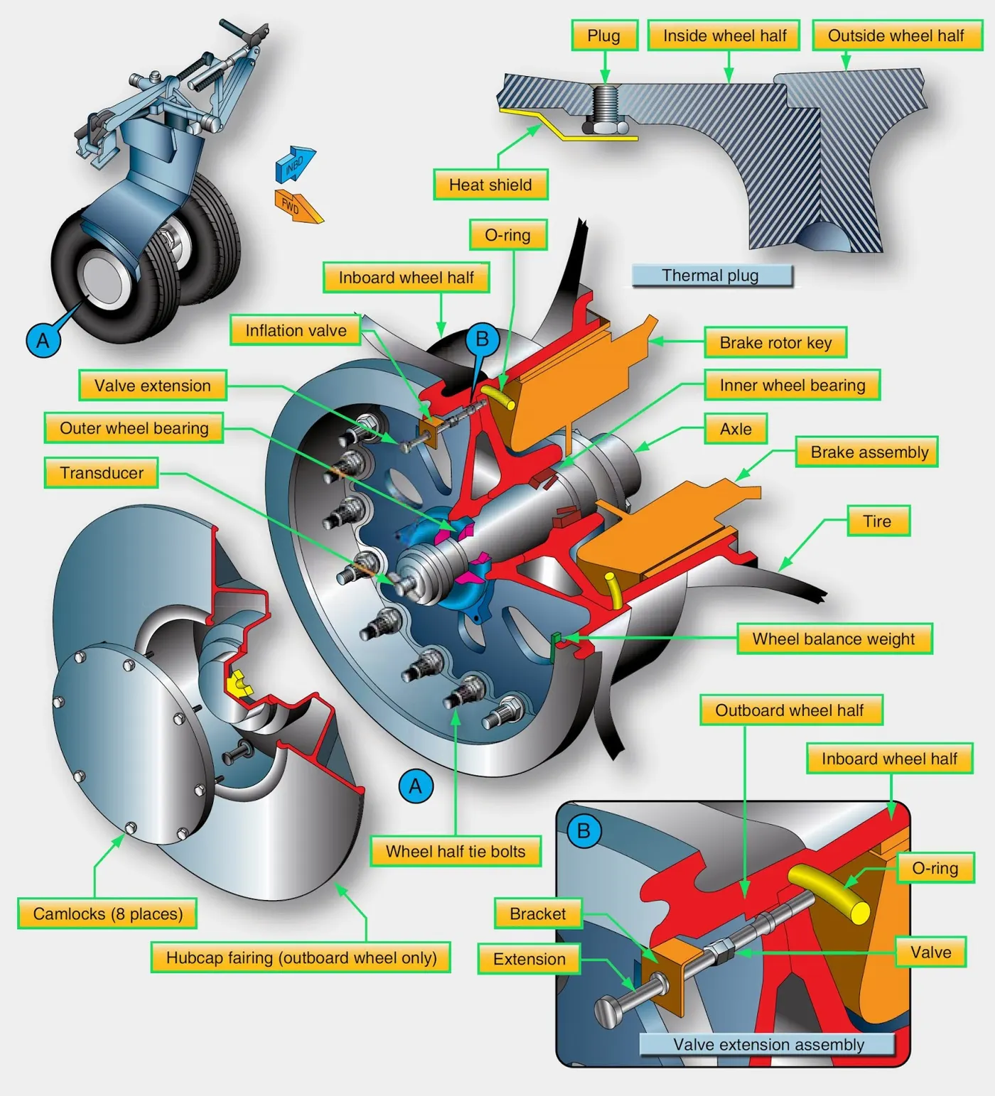
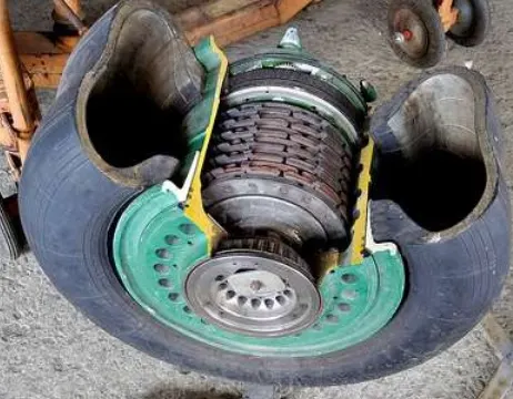
Aircraft wheels are an important component of a landing gear system. With tires mounted upon them, they support the entire weight of the aircraft during taxi, takeoff, and landing. The typical aircraft wheel is lightweight, strong, and made from aluminium alloy. Some magnesium alloy wheels also exist. Early aircraft wheels were of single-piece construction, much the same as the modern automobile wheel.
As aircraft tires were improved for the purpose they serve, they were made stiffer to better absorb the forces of landing without blowing out or separating from the rim. Stretching such a tire over a single piece wheel rim was not possible. A two-piece wheel was developed.
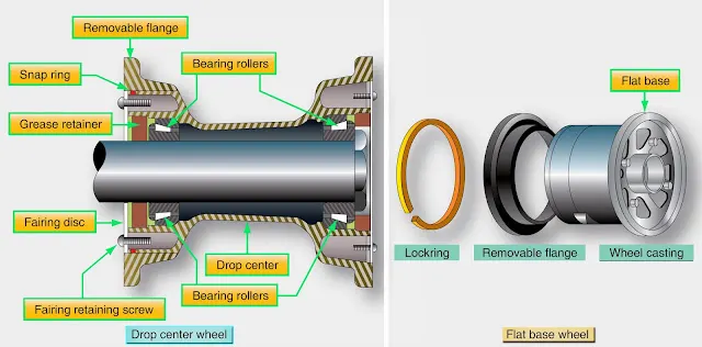
Early two-piece aircraft wheels were essentially one-piece wheels with a removable rim to allow mounting access for the tire. These are still found on older aircraft. Later, wheels with two nearly symmetrical halves were developed. Nearly all modern aircraft wheels are of this two-piece construction
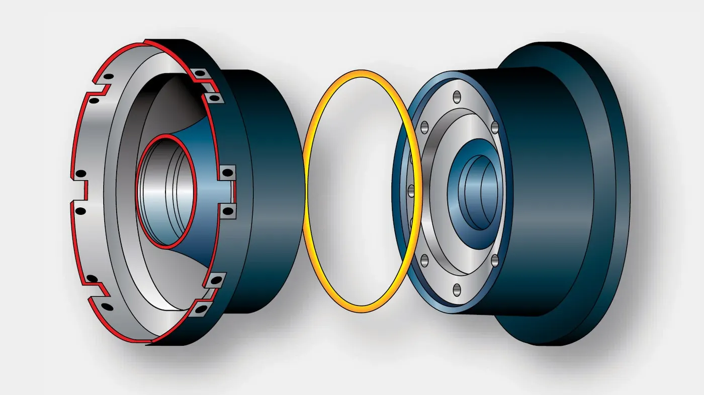
two-piece aircraft wheel found on a modern airliner
The typical modern two-piece aircraft wheel is cast or forged from aluminium or magnesium alloy. The halves are bolted together and contain a groove at the mating surface for an o-ring, which seals the rim since most modern aircraft utilize tubeless tires. The bead seat area of a wheel is where the tire actually contacts the wheel. It is the critical area that accepts the significant tensile loads from the tire during landing. To strengthen this area during manufacturing, the bead seat area is typically rolled to pre-stress it with a compressive stress load. Modern tyres are much more rigid, due to the load-bearing requirements, which results in the wheels having to be of two-piece construction.
Aircraft Tyre Pressure
Aircraft tires generally operate at high pressures, up to 200 psi (14 bar or 1,400 kPa) for airliners, and even higher for business jets. The main landing gear was typically inflated to 232 psi (16.0 bar), whilst its tail bumper gear tires were as high as 294 psi (20.3 bar). The high pressure and weight load tyres were a significant factor.
Tests of airliner aircraft tires have shown that they can sustain pressures of a maximum of 800 psi (55 bar; 5,500 kPa) before bursting. During the tests, the tires have to be filled with water, to prevent the test room from being blown apart by the energy that would be released by gas when the tire bursts.
Aircraft tires are usually inflated with nitrogen to minimize expansion and contraction from extreme changes in ambient temperature and pressure experienced during flight. Dry nitrogen expands at the same rate as other dry atmospheric gases (normal air is about 80% nitrogen), but common compressed air sources may contain moisture, which increases the expansion rate with temperature.
The requirement that an inert gas, such as nitrogen, be used instead of air for inflation of tires on certain transport category aeroplanes was prompted by at least three cases in which the oxygen in air-filled tires had combined with volatile gases given off by a severely overheated tire and exploded upon reaching autoignition temperature. The use of inert gas for tire inflation eliminates the possibility of a tire explosion
Task 6
With necessary assumptions, calculate the force and power required to push/pull an aircraft by a towing vehicle?.
Traction Force
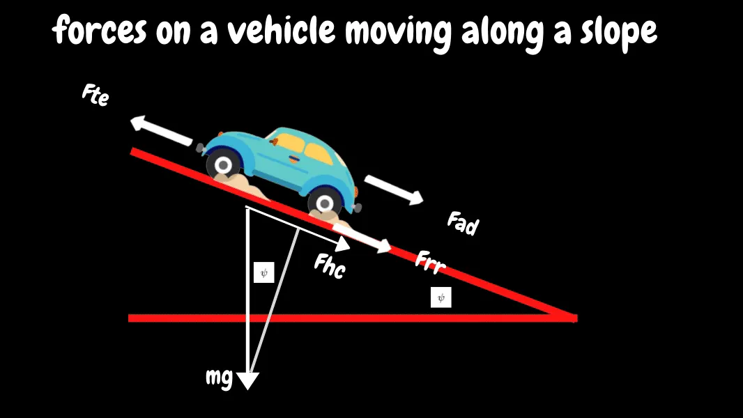
the force propelling the vehicle forward, transmitted to the ground through the drive wheels. The force propelling the vehicle forward, the tractive effort, has to accomplish
the following:
• Overcome the rolling resistance;
• Overcome the aerodynamic drag;
• Provide the force needed to overcome the component of the vehicle’s weight acting
down the slope
• Accelerate the vehicle, if the velocity is not constant.
1.Rolling Resistance Force (Frr)
due to the friction of the vehicle tyre on the road. Friction in bearings and the gearing system also play their part. The rolling resistance is approximately constant and hardly depends on vehicle speed. It is proportional to vehicle weight. The equation is:
Frr=μrrmg
where μrr- coefficient of rolling resistance
2.Aerodynamic Drag Force(Fad)
This part of the force is due to the friction of the vehicle body moving through the air. It is a function of the frontal area, shape, protrusions such as side mirrors, ducts and air passages, spoilers, and many other factors. The formula for this component is:
Fad=(12)(ρACdV^2)
where
ρ→density of air,
A→frontal area,
Cd→coefficient of drag,
V→velocity.
3.Hill Climbing Force (Fhc)
The force needed to drive the vehicle up a slope. is simply the component of the vehicle weight that acts along the slope. The equation is:-
Fhc=mgsin(ψ)
Fte=Frr+Fad+Fhc
Here neglected the hill-climbing force, acceleration force.
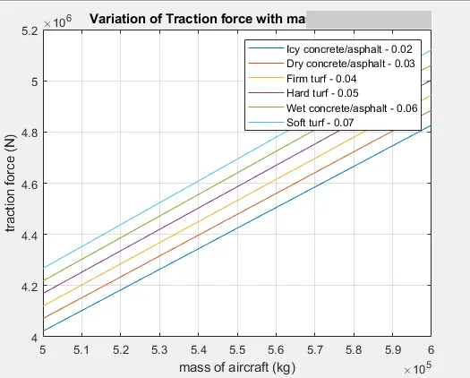
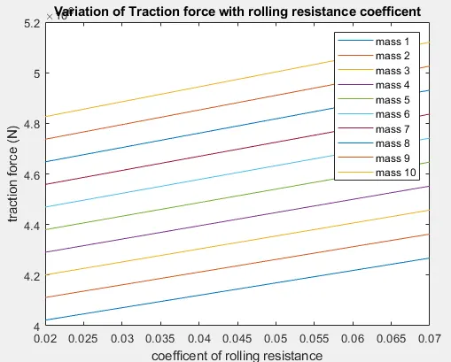
An array for rolling resistance coefficient and an array for the mass of the aircraft. So for each rolling resistance coefficients and each mass of aircraft, the traction force of the aircraft, power and torque produced is calculated in the following Matlab code.
%PROGRAM TO CALCULATE THE TRACTION FORCE, POWER & TORQUE OF AN AIRCRAFT

clear all
close all
clc

%ASSUMED VALUES
urr =[0.02,0.03,0.04,0.05,0.06,0.07];
u = 0.8;
m = linspace(500000,600000,10);
g = 9.81;
rho = 1.25;
A = 158.3;
cd =0.02;
v = 3;
r = 0.35;
G = 20;

frr = zeros(6,10);
fad = zeros(6,10);
ffr = zeros(6,10);
fte = zeros(6,10);


%FOR LOOP FOR FORCE CALCULATIONS
for i=1:6
    for j=1:10
        frr1 = urr(i).*m(j)*g;
        frr(i,j) = frr1;

        fad1 = 0.5*rho*A*cd*v^2;
        fad(i,j) = fad1;

        ffr1 = u*m(j).*g;
        ffr(i,j)= ffr1;

        fte(i,j) = frr(i,j) + fad(i,j) + ffr(i,j);
    end
end

%POWER CALCULATION
P = (fte .* v)/1000;


%TORQUE CALCULATION
T = (fte .* r)/G;


figure
plot(m,fte)
xlabel('mass of aircraft (kg)')
ylabel('traction force (N)')
title('Variation of Traction force with mass of aircraft')
legend("Icy concrete/asphalt - 0.02","Dry concrete/asphalt - 0.03","Firm turf - 0.04","Hard turf - 0.05","Wet concrete/asphalt - 0.06","Soft turf - 0.07")%legend
grid on

figure
plot(urr,fte)
xlabel('coefficent of rolling resistance')
ylabel('traction force (N)')
title('Variation of Traction force with rolling resistance coefficent')
legend("mass 1","mass 2","mass 3","mass 4","mass 5","mass 6","mass 7","mass 8","mass 9","mass 10")
OUTPUT
Task 7
Design an electric powertrain with the type of motor, its power rating, and energy requirement to fulfil aircraft towing application.
Estimate the duty cycle range to control the aircraft speed from zero to highest.
Make all required assumptions.
Prepare a table of assumed parameters.
Draw a block diagram of the powertrain.
Assumptions
for doing this problem, I have considered the values realated to aircraft like -
aircraft weight = 31298 kg
towing tractor = 1100kg
coefficent of drag = 0.02
coefficent of rolling resistance = 0.03
frontal area = 158.3 Sq.m
Rolling resistance coefficent = 0.03
Velocity = 10km/hr =3 m/sec
Power = 19000 pound-force = 84.516 KN = 84516.21 N
towing tractors wheel radius = 0.35m
gear ratio = 20
velocity = 10km/hr = 3m/sec
density of air = 1.25kg/m^3
acceleration of gravity = 9.81m/sec^2
advisor tool to design the motor ratings.
Type of Motor and Motor Power ratings
for motor specifications and rating
motor model - MC_AC30, Siemens AC 30 kW induction motor/controller
Maximum power - 250KW
Efficiency - 86%
Mass of motor - 58Kg
Voltage - 216V
Peak current - 280A
Minimum Voltage - 140V
The powertrain for Aircraft Towing Tractor
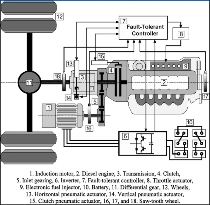
Now, Let look at the program to calculate the traction force required to tow the aircraft using the above
defined motor ratings are as shown below -
%PROGRAM TO CALCULATE THE TRACTION FORCE, POWER & TORQUE OF AN AIRCRAFT

clear all
close all
clc

%ASSUMED VALUES
urr = 0.03;
u = 0.2;
ma = 31298;
mt = 1100;
g = 9.81;
rho = 1.25;
A = 158.3;
cd =0.02;
v = 3;
r = 0.35;
G = 20;

%FORCE CALCULATION
frr = urr*(ma+mt)*g;
fad = 0.5*rho*A*cd*v^2;
ffr = u*(ma+mt)*g;

%TRACTION FORCE CALCULATION
Traction_force_in_N = (frr + fad + ffr) Output
Traction_force_in_N =
7.3117e+04
Power_KW =
219.3522
The Output power required to pull the aircraft & the towing tractor will be 219.3522 KW
And the selected motors power rating is 250KW, which becomes the input power required by the motor.
Hence the duty cycle range is calculated by finding the ratio of output to input power
i.e. Pin/ Pout=`19.35/25`
=0.8774
so we can say the duty cycle range is from 0 to 87.74%.
Now, assume that the tractor takes 10 min or 600sec to taxing (i.e. tow the aircraft from gate to runway)
Hence the energy required to fulfil aircraft towing application (E) = Pout * t
i.e. E = 219.3522 * 600
E = 131.611MJ