Project 1 - MODELLING, ANALYSIS & DESIGN OF TALL BUILDINGS IN ETABS
Question. A 30 - 40hr project on modelling, analysis & design of a state-of-the-art tall building using ETABS software.
Key Highlights:
a. Modelling:
- To comprehend the architectural plan provided by the architect and look-out for the key information from the drawings.
- Import the architectural floor plan (provided by the architect) in ETABS model to start with the modelling.
- Create grid lines, story levels & story heights to set-up a project.
- Create material definitions for the concrete, rebar & structural steel.
- Create slab, beam, column & wall properties to be used further in the project.
- Model typical floor plate using shell & frame elements as indicated in architectural plan.
b. Loadings & Load combinations:
- Define load patterns for gravity cases
- Define load patterns for the lateral load cases using the wind & seismic parameters provided.
- Create service & ultimate load combinations as per IS 456:2000
- Define mass source for the earthquake loads
c. Structural Analysis:
- Obtain the shear force & moment diagram for the floor beams & columns
- Check the gravity load path in the structure if it follows the designer’s intent.
- Perform quick hand calculations to confirm the base reactions for the gravity load cases.
d. Design of structural members:
- Select appropriate parameters for the design of the members
- Interpret the design results
- Re-design and restrict the member utilization within 0.9
- Identify the reinforcement requirements for each structural member
Key Deliverables:
- Manual calculations for the base reactions in gravity load cases (in excel / word document)
- Submit ETABS model with the complete model of the tall building (exported .e2k format, do not attach .EDB format directly)
- The model should pass all design and serviceability requirements.
- A comprehensive project report from the ETABS software (as PDF file).
Solution:
a. Modelling:
- To comprehend the architectural plan provided by the architect and look-out for the key information from the drawings.
- Import the architectural floor plan (provided by the architect) in ETABS model to start with the modelling.
- Create grid lines, story levels & story heights to set-up a project.
- Create material definitions for the concrete, rebar & structural steel.
- Create slab, beam, column & wall properties to be used further in the project.
- Model typical floor plate using shell & frame elements as indicated in architectural plan.
Solution:
- Import the architectural floor plan (provided by the architect) in ETABS model to start with the modelling:
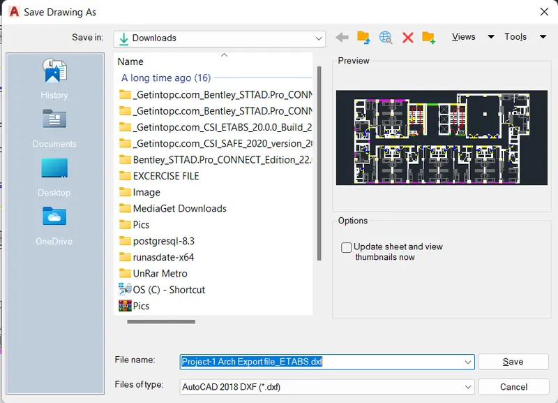
- In order to import the architectural floor plan which is provided by the architect in ETABS model,go to the AutoCAD software,open the model in the AutoCAD and then save as the file in the dxf. format just as shown in the below given image:
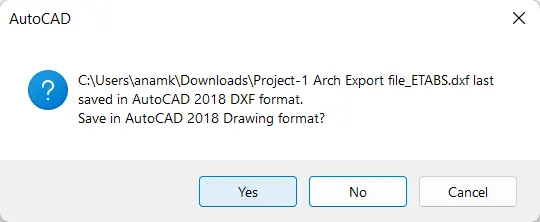
- Now safe the file in the dwg.form and then quit the AutoCAD software just as shown in the below given image:
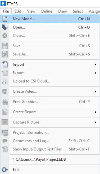
- Now go to the ETABS software,go to the file option then there will be an option called New Model just click on that option just as shown in the below given image:
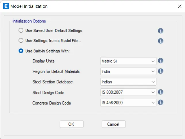
- After this there will be a dialouge box named as the model initialization,in that dialouge box fill the necessary details and click OK just as shown in the below given image:
- Create grid lines, story levels & story heights to set-up a project:
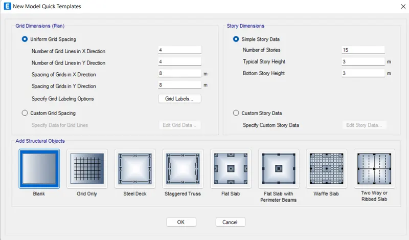
- And after that there will be another dialouge box, where we will be given the details regarding the stories,grids etc just as shown in the below given image:
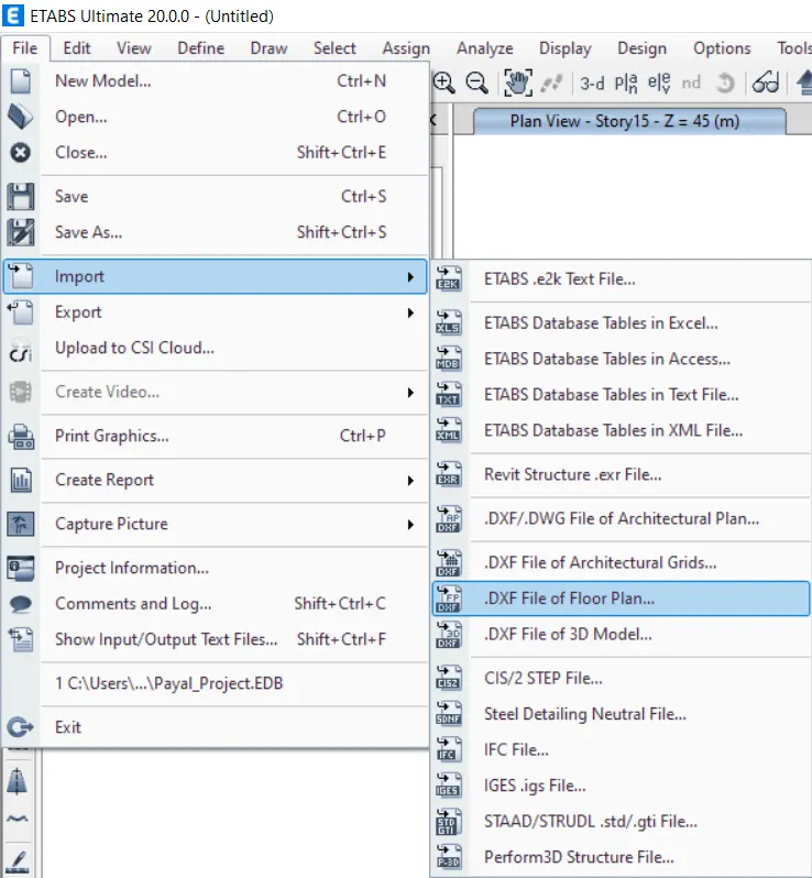
- And now we will be importing the AutoCAD architectural file,in order to import the file into ETABS save the file as .dxf in the AutoCAD and then go to the ETABS software click on the file option there will be a drop-down list in that list there will be an option called Import just click on that option.
- After clicking on the Import there will be another drop-down list and in that list there will be another option called .dxf file of the floor plan just click on that option just as shown in the below given image:
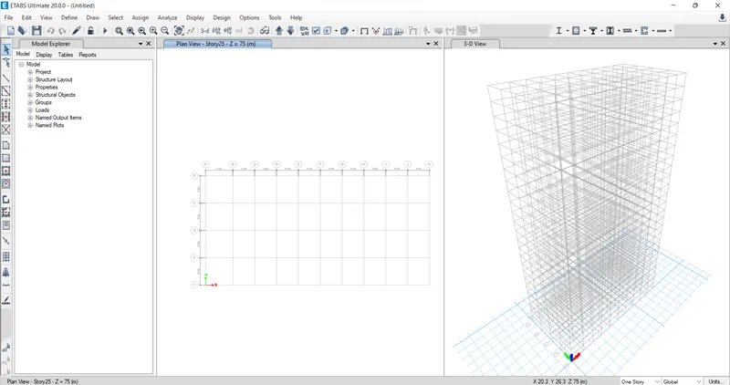
- Below is the image which shows the model after creating grid lines,story level and the story height:
- Create material definitions for the concrete, rebar & structural steel:
- First we will be creating the materials in the ETABS.
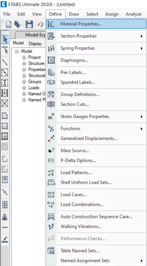
- So in order to create the material,go to the Define option just click on the Define option then there will be a drop-down list and in that list there will be an option called Material properties just click on that option just as shown in the below given image:
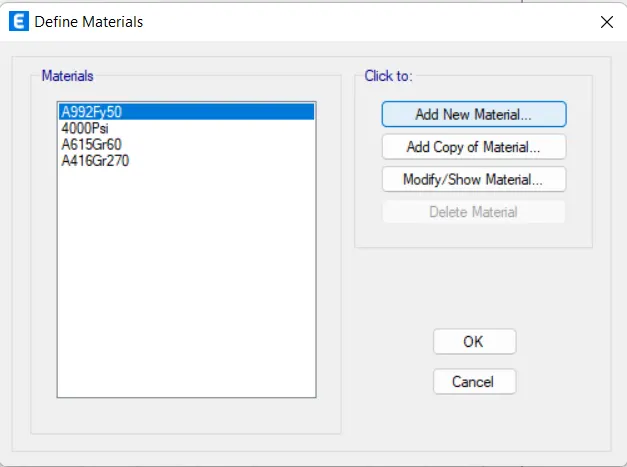
- After clicking the material properties then there will be another dialouge box there will be another dialouge box named as the Define materials and in that dialouge box there will be an option called Add New Material just as shown in the below given image:
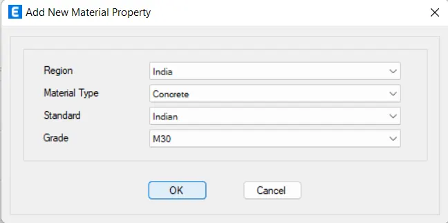
- And then there will be another dialouge box and in that dialouge box there will be another dialouge box named as the Add New Material Property just as shown in the below given image:
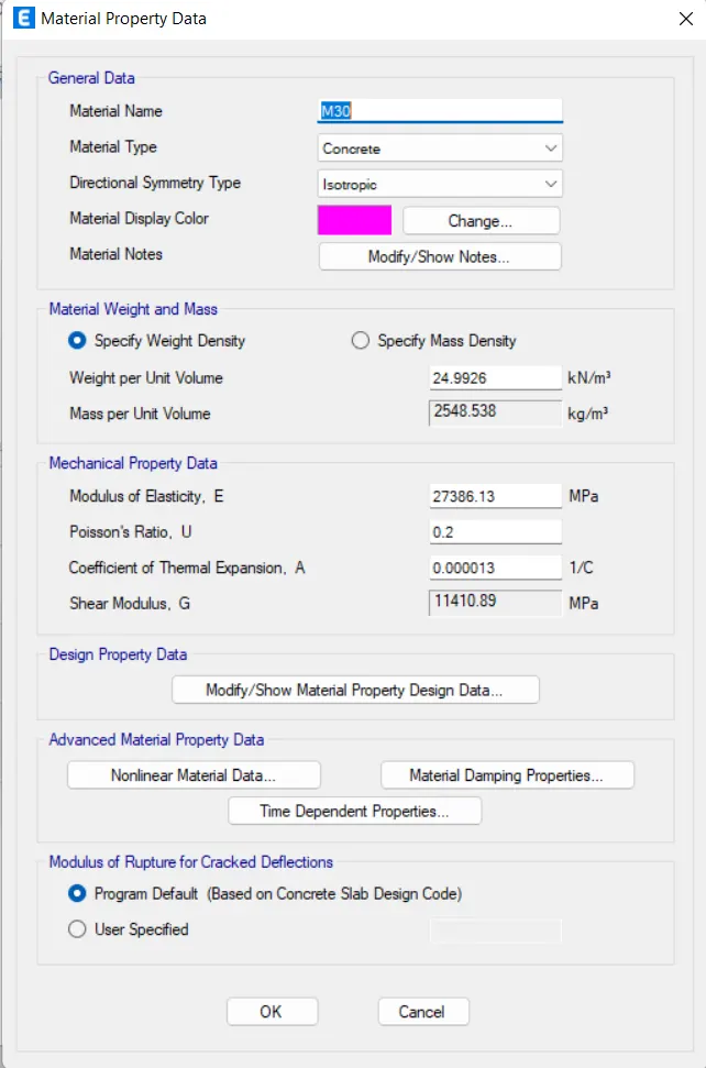
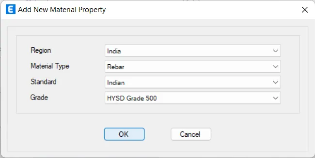
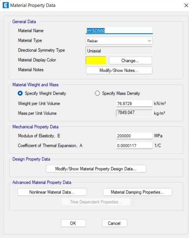
- Now add the rebar HYSD500 just as shown in the below given image:
- Create slab, beam, column & wall properties to be used further in the project:
- So in order to create slab,beam,column and the wall properties we will be using the section properties.
Beam(400X500):
- So first of all we will be defining the beam,so in order to assign the beam first we will be clicking on the Define option after clicking on the define option there will be a drop-down list and in that list there will be another option section properties.
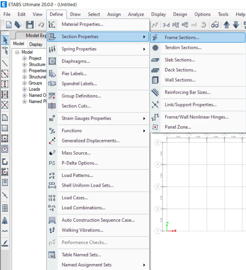
- After clicking the section properties there will be another drop-down list and in that drop-down list there will be another option called Frame section just click on that option just as shown in the below given image:
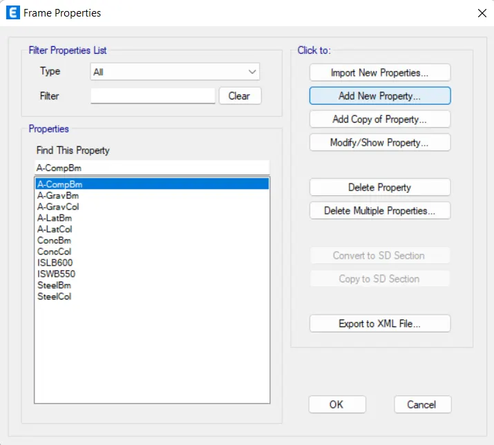
- After that there will be another dialouge box there will be named as the Frame properties and then there will be an option called Add New Property just click on that option just as shown in the below given image:
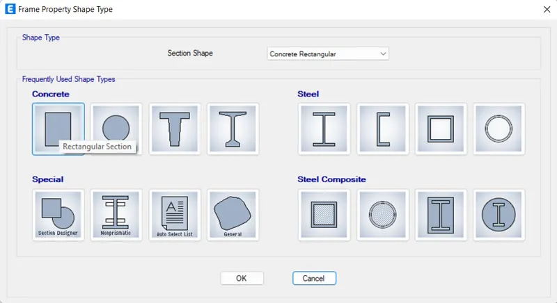
- And after clicking on the Add New Property there will be another dialouge box named as the Frame Property Shape Type and in that dialouge box there will be an option called Rectangular Concrete and then click OK just as shown in the below given image:
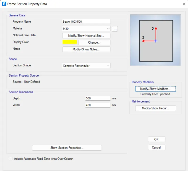
- And then there will be another dialouge box named as the Frame Section Property Data, and then fill all the details just as shown in the below given image:
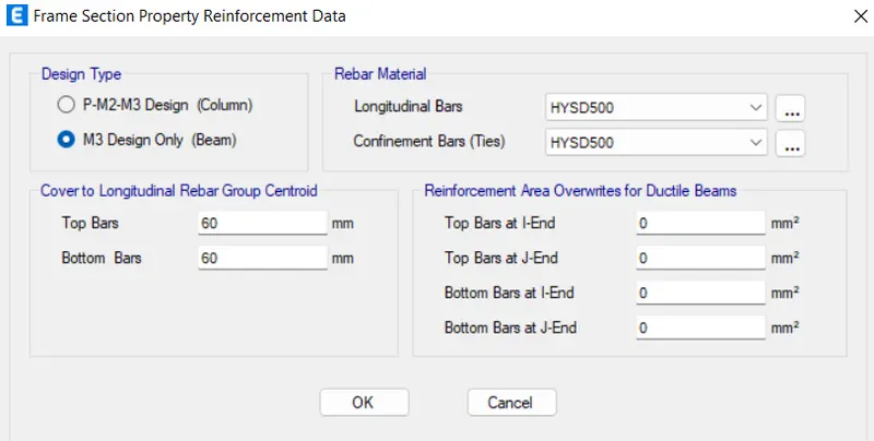
- Then there is another option named as the Modift/Show Rebar just click on that option then there will be another dialouge box named as the Frame Section Property Reinforcement Data and now there will be other option Design Type and the other options just as shown in the below given image:
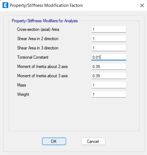
- And after that there will be another option Modify/Show Modifiers just click on the option.
- And then there will be another dialouge box named as the Property/Stiffness Modification Factors and fill the other information just as shown in the below given image:
Column(500X500):
- So now we will be assigning the columns for this project.
- So first of all we will be defining the column,so in order to assign the column first we will be clicking on the Define option after clicking on the define option there will be a drop-down list and in that list there will be another option section properties.
- After clicking the section properties there will be another drop-down list and in that drop-down list there will be another option called Frame section just click on that option just as shown in the below given image:
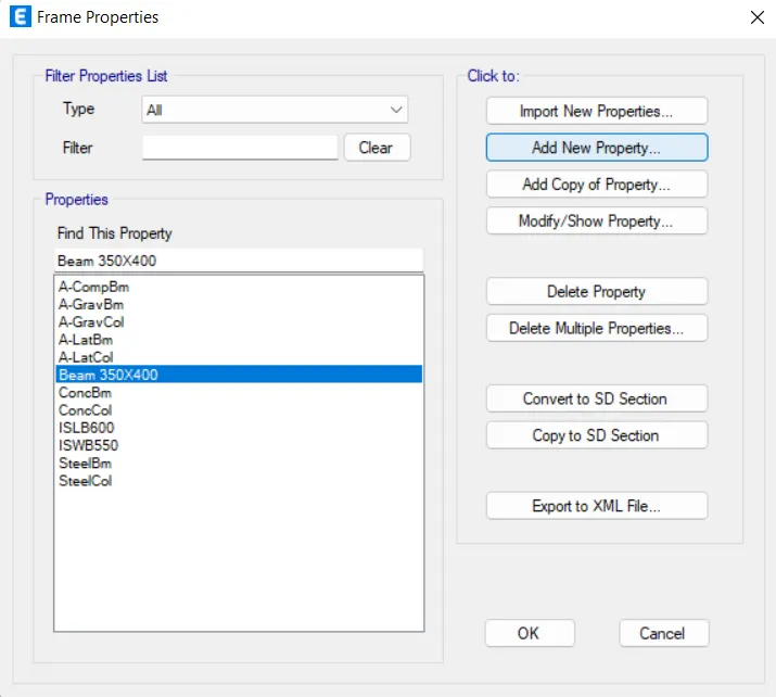
- After that there will be another dialouge box there will be named as the Frame properties and then there will be an option called Add New Property just click on that option just as shown in the below given image:
- And after clicking on the Add New Property there will be another dialouge box named as the Frame Property Shape Type and in that dialouge box there will be an option called Rectangular Concrete and then click OK just as shown in the below given image:
- And then there will be another dialouge box named as the Frame Section Property Data, and then fill all the details just as shown in the below given image:
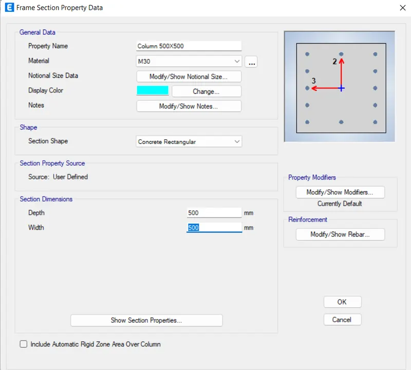
- Then there is another option named as the Modift/Show Rebar just click on that option then there will be another dialouge box named as the Frame Section Property Reinforcement Data and now there will be other option Design Type and the other options just as shown in the below given image:
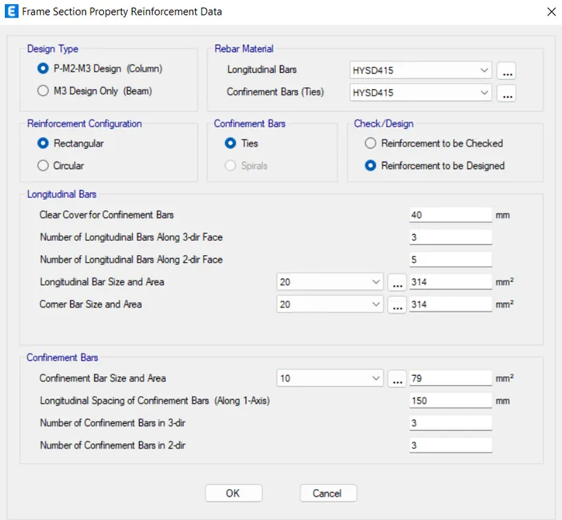
- And after that there will be another option Modify/Show Modifiers just click on the option.
- And then there will be another dialouge box named as the Property/Stiffness Modification Factors and fill the other information just as shown in the below given image:
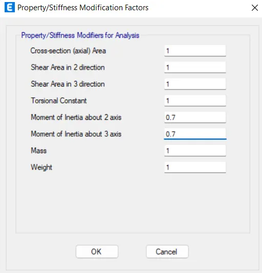
Column(800X800):
- So now we will be assigning the columns for this project.
- So first of all we will be defining the column,so in order to assign the column first we will be clicking on the Define option after clicking on the define option there will be a drop-down list and in that list there will be another option section properties.
- After clicking the section properties there will be another drop-down list and in that drop-down list there will be another option called Frame section just click on that option just as shown in the below given image:
- After that there will be another dialouge box there will be named as the Frame properties and then there will be an option called Add New Property just click on that option just as shown in the below given image:
- And after clicking on the Add New Property there will be another dialouge box named as the Frame Property Shape Type and in that dialouge box there will be an option called Rectangular Concrete and then click OK just as shown in the below given image:
- And then there will be another dialouge box named as the Frame Section Property Data, and then fill all the details just as shown in the below given image:
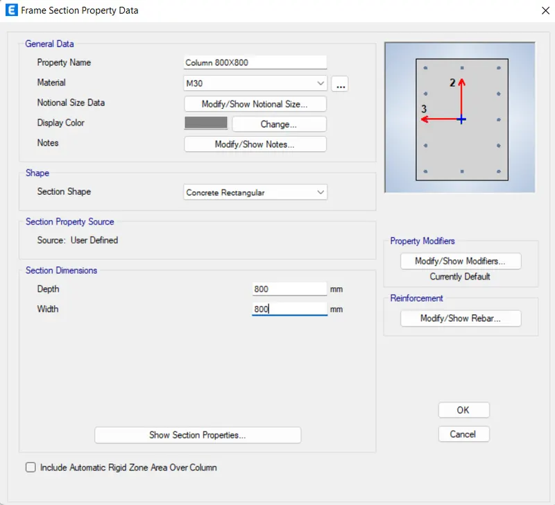
- Then there is another option named as the Modift/Show Rebar just click on that option then there will be another dialouge box named as the Frame Section Property Reinforcement Data and now there will be other option Design Type and the other options just as shown in the below given image:
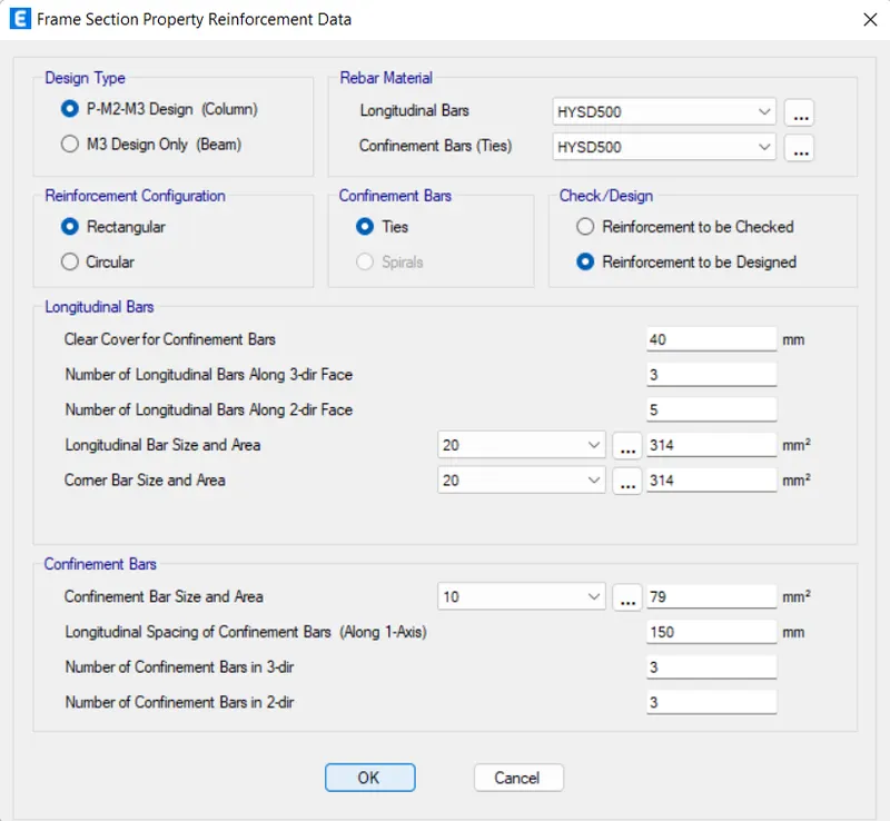
- And after that there will be another option Modify/Show Modifiers just click on the option.
- And then there will be another dialouge box named as the Property/Stiffness Modification Factors and fill the other information just as shown in the below given image:
SLAB(150):
- So now we will be assigning the slab for this project.
- So first of all we will be defining the slab,so in order to assign the slab first we will be clicking on the Define option after clicking on the define option there will be a drop-down list and in that list there will be another option section properties.
- After clicking the section properties there will be another drop-down list and in that drop-down list there will be another option called Slab Sections just click on that option just as shown in the below given image:
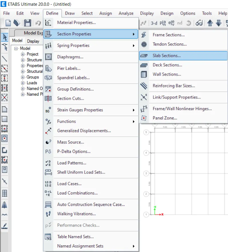
- After that there will be another dialouge box there will be named as the Slab Properties and then there will be an option called Add New Property just click on that option just as shown in the below given image:
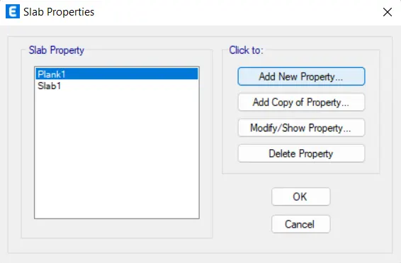
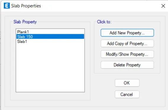
- And after clicking on the Add New Property there will be another dialouge box named as the Slab Property Data and in that dialouge box there will be other options fill the necessary details as shown below and then click OK just as shown in the below given image:
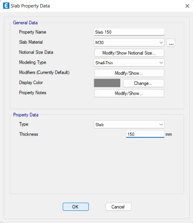
- And then there will be other dialouge box and then click OK just as shown in the below given image:
WALL(250):
- And now we will be assigning the wall properties.
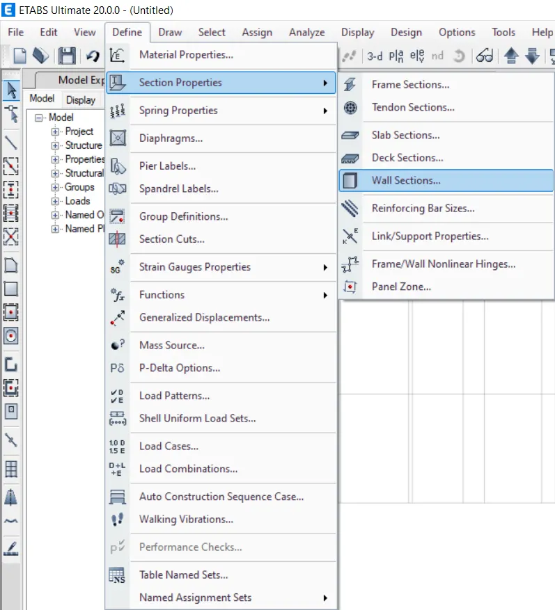
- And in order to assign the wall property,first go to the option Define click on that option then there will be a drop-down list and in that drop-down list there will be an option called Section properties and then there will be another drop-down list and in that list there will be another option called Wall Section just click on that option just as shown in the below given image:
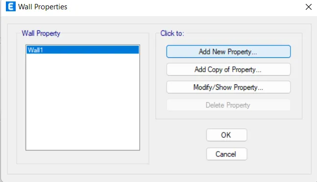
- After clicking on that option there will be another dialouge box there will be another dialouge box named as the Wall Properties,and in that dialouge box there will be an option called Add New Property click on that option just as shown in the below given image:
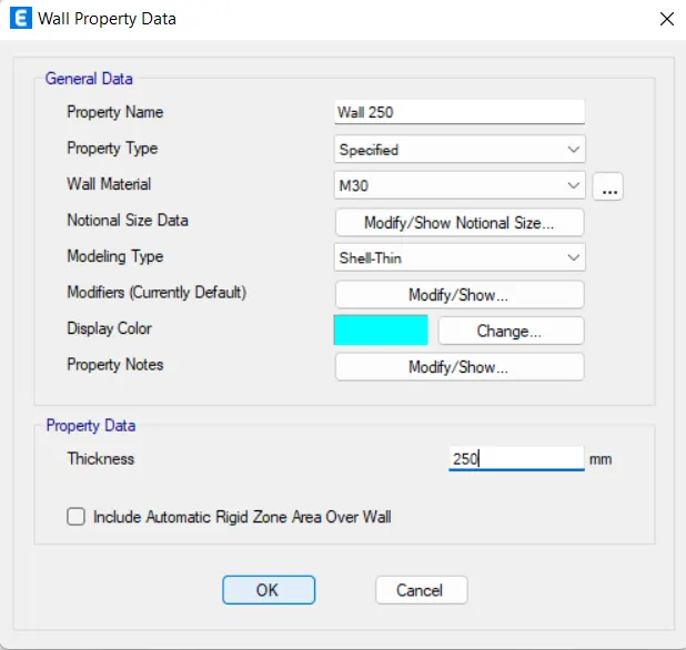
- And after that there will be another dialouge box named as the Wall Property Data and in that dialouge box there are the options fill out all the necessary details and just click OK just as shown in the below given image:
WALL(150):
- And now we will be assigning the wall properties.
- And in order to assign the wall property,first go to the option Define click on that option then there will be a drop-down list and in that drop-down list there will be an option called Section properties and then there will be another drop-down list and in that list there will be another option called Wall Section just click on that option just as shown in the below given image:
- After clicking on that option there will be another dialouge box there will be another dialouge box named as the Wall Properties,and in that dialouge box there will be an option called Add New Property click on that option just as shown in the below given image:
- And after that there will be another dialouge box named as the Wall Property Data and in that dialouge box there are the options fill out all the necessary details and just click OK just as shown in the below given image:
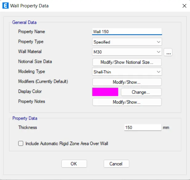
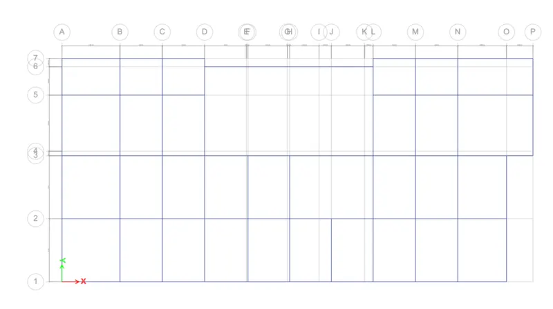
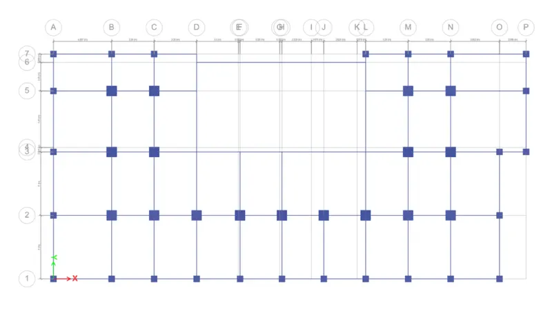
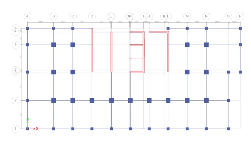
- Now we have defined the all properties and now we need to place the all components in the project in ETABS just as shown in the below given image:
BEAM:
COLUMN:
WALL:
- Model typical floor plate using shell & frame elements as indicated in architectural plan:
SLAB:
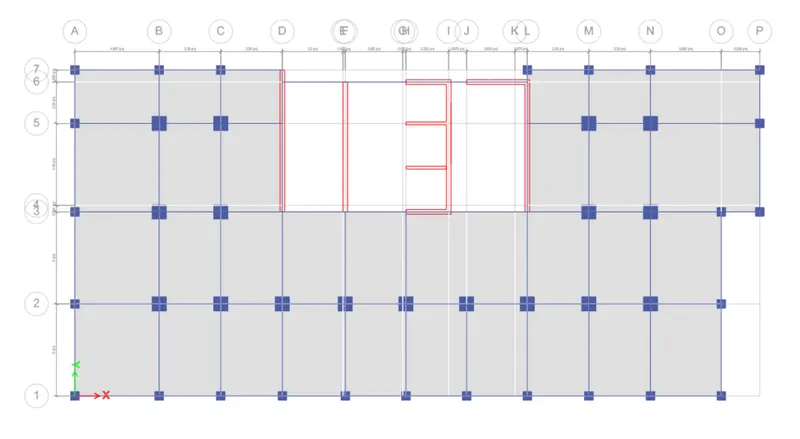
b. Loadings & Load combinations:
- Define load patterns for gravity cases.
- Define load patterns for the lateral load cases using the wind & seismic parameters provided.
- Create service & ultimate load combinations as per IS 456:2000.
- Define mass source for the earthquake loads.
- Define load patterns for gravity cases:
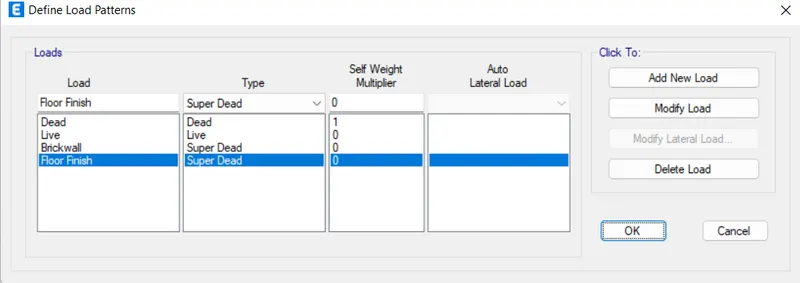
- Now we will be defining the load patterns for the gravity cases.
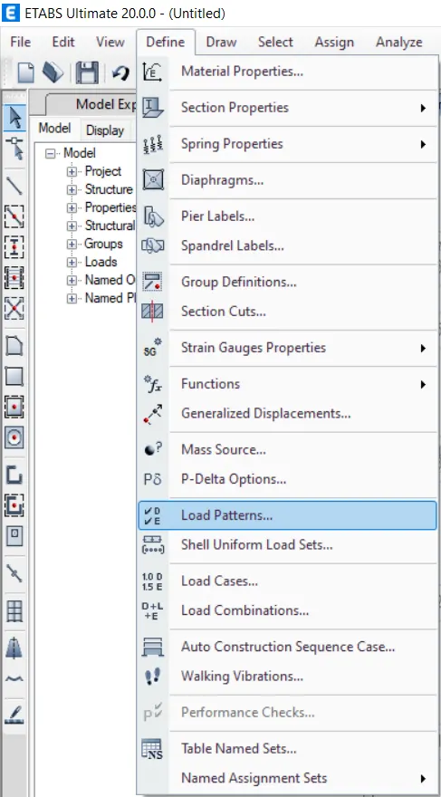
- So in order to define the load patterns,first go to the define option then there will be a drop-down list and in that list there will be an option called Define just click on that option.
- After clicking on that option there will be another drop-down list and in that list there will be another option called Load Patterns just click on that option just as shown in the below given image:
- And then after clicking on the Load Patterns then there will be another dialouge box named as the Define Load Patterns and in that dialouge box fill out the all necessary details and then just click on OK just as shown in the below given image:
- Define load patterns for the lateral load cases using the wind & seismic parameters provided:
- Now we will be assigning the load patterns for the lateral load cases using the wind and the seismic parameters provided.
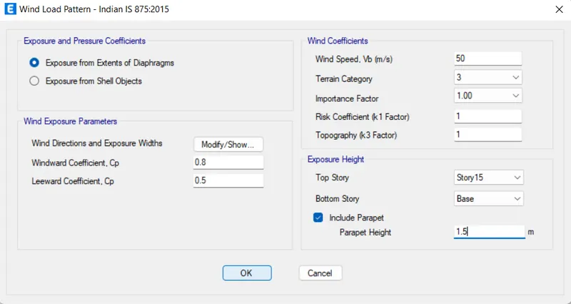
- For the wind load we will be considering the Chennai as the location for our building:
Basic Wind Speed - 50m/s.
Terrain Category - 3
k1 - 1
k2 - 1.105
k3 - 1
k4 - 1
- So in order to assign the load patterns,we will be going to the option Define just click on the define option and then there will be another drop-down list and in that list there will be an option named as the load patterns just click on that option just as shown in the below given image:
- And then after clicking on the Load Patterns then there will be another dialouge box named as the Define Load Patterns and in that dialouge box fill out the all necessary details and then just click on OK just as shown in the below given image:
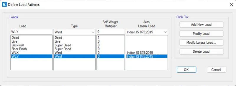
- After this there will be an option called Modify Lateral Load just click on that option,and after clicking on the Modify Lateral Load there will be another dialouge box named as the Wind load patterns:IS 875:2015 and in that dialouge box fill the all necessary data just as shown in the below given image:
- And after that we will be assigning the dead loads,live load and the seismic loads just as shown in the below given image:
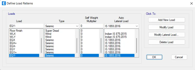
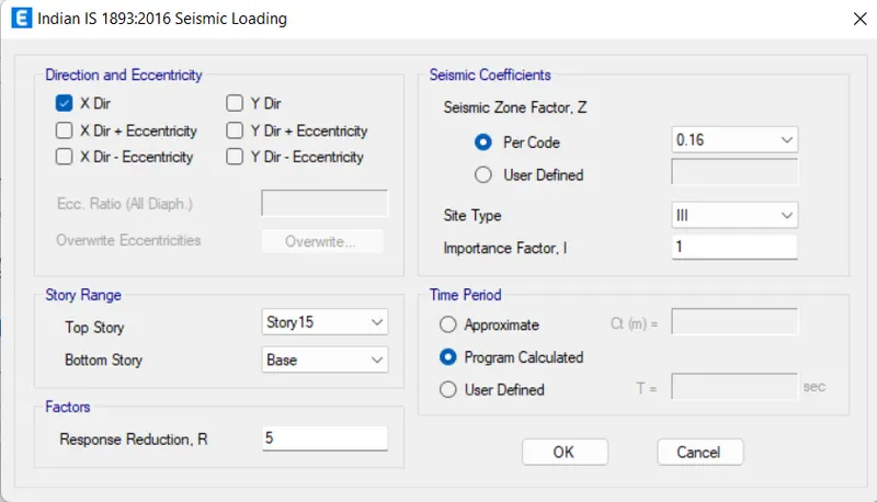
- And now as per IS-1893 Chennai is in seismic zone-lll and the zone factor is 0.16 according to the Indian Standard IS-1893.
- And in the dialouge box Define Load Patterns there will be another option called Modify Lateral Load just click on that option for the seismic load EQX.
- And after clicking on that option there will be another dialouge box named as the Indian IS-1893:2016 Seismic Loadings and fill out the all necessary details just as shown in the below given image:
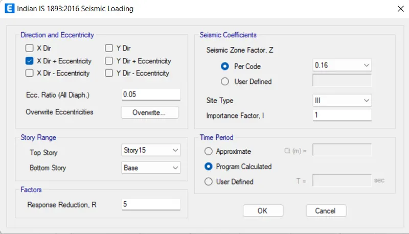
- And now do the same procedure as of the other seismic loads.
For EQX+:
For EQX-:
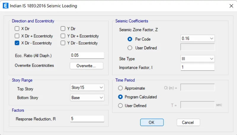
For EQY:
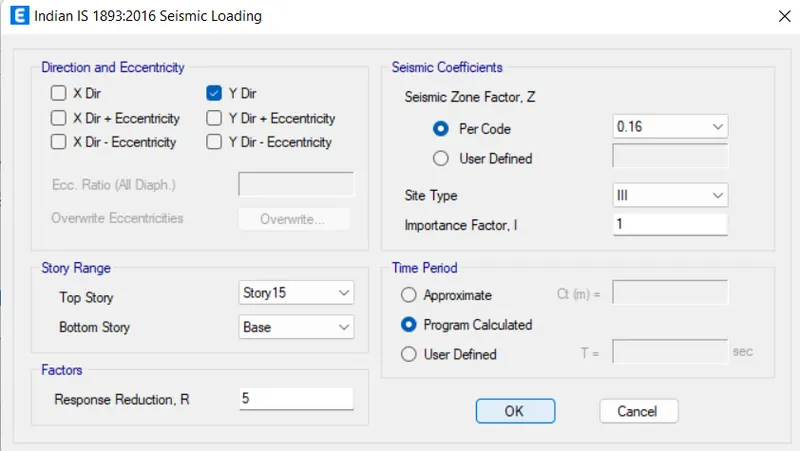
For EQY+:
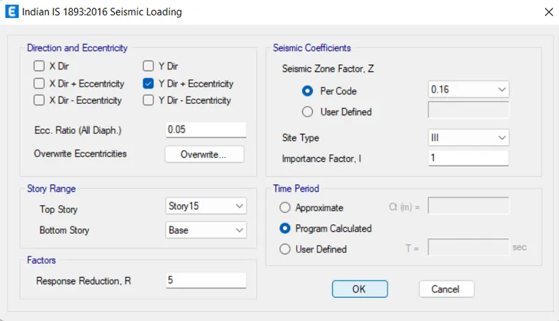
For EQY-:
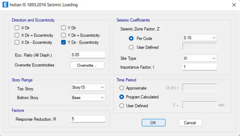
- After this,now we will be assigning these loads in the software.
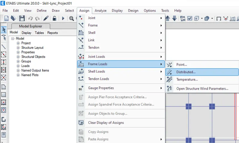
- And to assign these loads,go to the Assign option just click on that option,after clicking on that option there will be a drop-down list and in that list there will be an option named as the Frame Loads click on that option and after that there will be another drop-down list named as the Distributed again click on that option just as shown in the below given image:
- And we know according to the IS code 875:Part2:
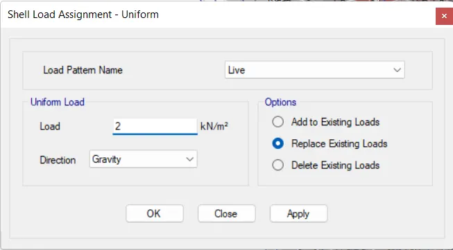
- Live load - 2 kN/sq.m.
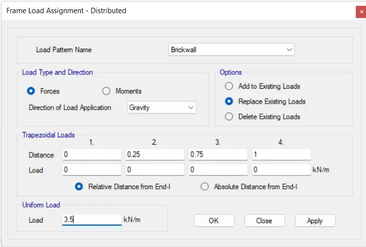
- Brickwall load - 3.5 kN/m.
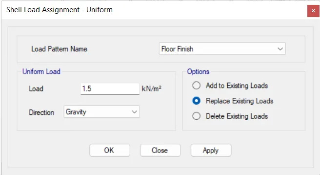
- Floor Finishes - 1.5 kN/sq.m.
- Parapet wall - 1 kN/m
- And after clicking on the option there will be another dialouge box named as the Frame Load Assignment-Distributed and in that dialouge box fill out the all necessary details just as shown in the below given image:
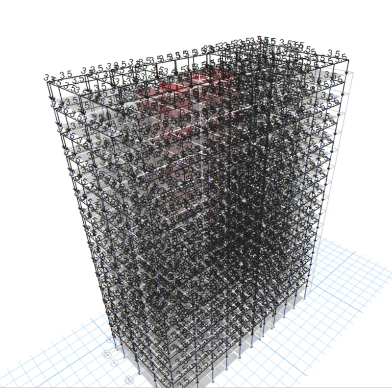
- Below is the 3-D image of the building after assgning the Brickwall loads just as shown in the below given image:
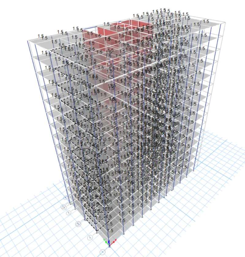
- And now we will be assigning the floor finish.
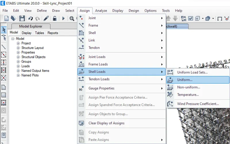
- So in order to assign the floor finish,just go to the assign option click on that option then there will be a drop-down list and in that list there will be an option called Shell Loads just click on that option after that there wll be another drop-down list and in that list there will be another option called Uniform just click on that option just as shown in the below given image:
- After that there will be another dialouge box named as the Shell Load Assignment-Uniform and in that dialouge box just fill the all necessary details just as shown in the below given image:
- Below is the 3-D image of the building after assgning the Floor finish loads just as shown in the below given image:
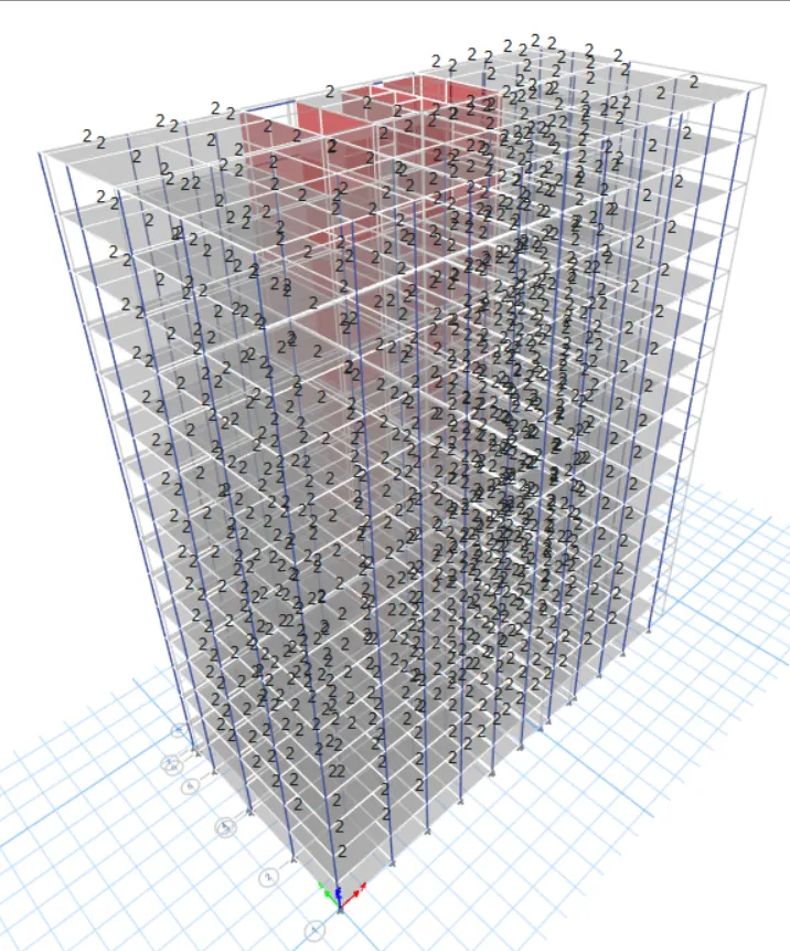
- And now we will be assigning the Live Load.
- So in order to assign the Live Load,just go to the assign option click on that option then there will be a drop-down list and in that list there will be an option called Shell Loads just click on that option after that there wll be another drop-down list and in that list there will be another option called Uniform just click on that option just as shown in the below given image:
- After that there will be another dialouge box named as the Shell Load Assignment-Uniform and in that dialouge box just fill the all necessary details just as shown in the below given image:
- Below is the 3-D image of the building after assgning the Floor finish loads just as shown in the below given image:
- And to assign these loads,go to the Assign option just click on that option,after clicking on that option there will be a drop-down list and in that list there will be an option named as the Frame Loads click on that option and after that there will be another drop-down list named as the Distributed again click on that option just as shown in the below given image:
- And after clicking on the option there will be another dialouge box named as the Frame Load Assignment-Distributed and in that dialouge box fill out the all necessary details just as shown in the below given image:
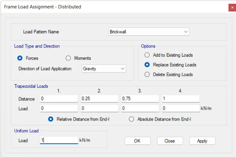
- Below is the 3-D image of the building after assgning the Brickwall loads just as shown in the below given image:
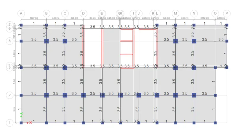
- Define mass source for the earthquake loads:
- Now we will be assigning the mass source for the earthquake loads.
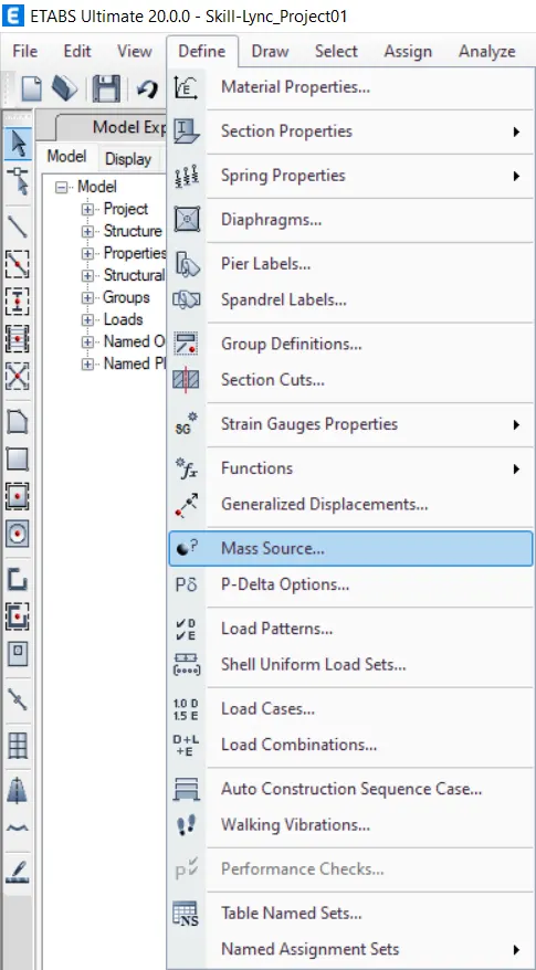
- And in order to assign the mass source,first we go to the Define tab just click on that option then there will be a drop-down list and in that list there will be an option called Mass Source click on that option just as shown in the below given image:
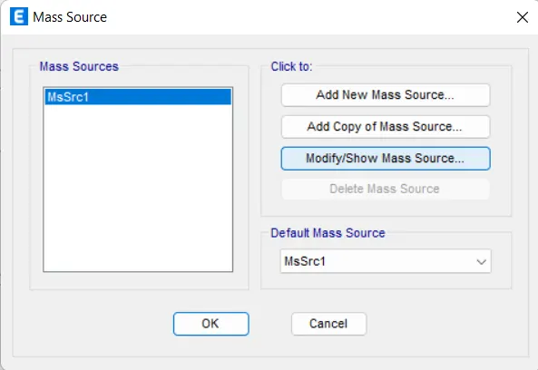
- After clicking on the Mass source option there will be a dialouge box named as the Mass Source and in that dialouge box there will be an option called Modify/Show Mass Source just click on that option just as shown in the below given image:
- After that there will be another dialouge box named as the Mass source data and in that dialouge box fill out the all necessary details just as shown in the below given image:
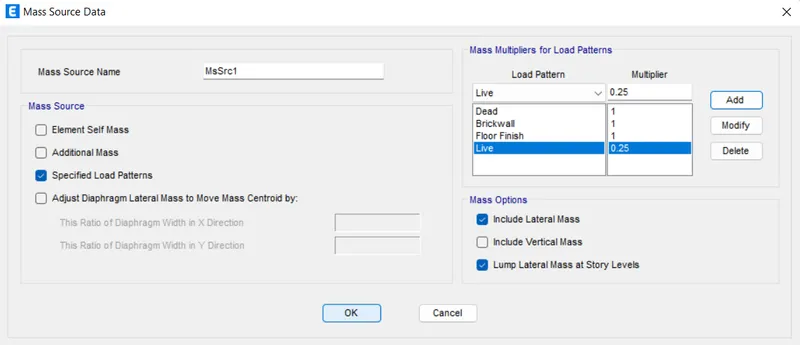
- Next after defining the mass sources,now we will be assigning the Modal Cases.
- And to assign the Modal cases,go to the Define tab just click on that option then there will be a drop-down list and in that list there will be an option named as the
- After assigning the modal cases we will be defining the Response Spectrum function.
- And in order to assign the response spectrum function,go to the Define tab click on the Define option then there will be a drop-down list and in that list there will be an option called Functions click on that option after that there will be another drop-down list and in that list there will be another option called Response Spectrum click on that option just as shown in the below given image:
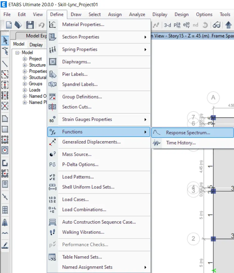
- After this there will be another dialouge box named as the Define Response Spectrum Functions and in that dialouge box there will be another option called Add New Function just click on that option just as showsn in the below given image:
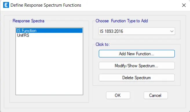
- After this there will be another dialouge box named as the Response Spectrum Function Definition-IS 1893:2016 and fill out the all necessary details just as shown in the below given image:
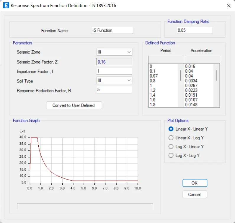
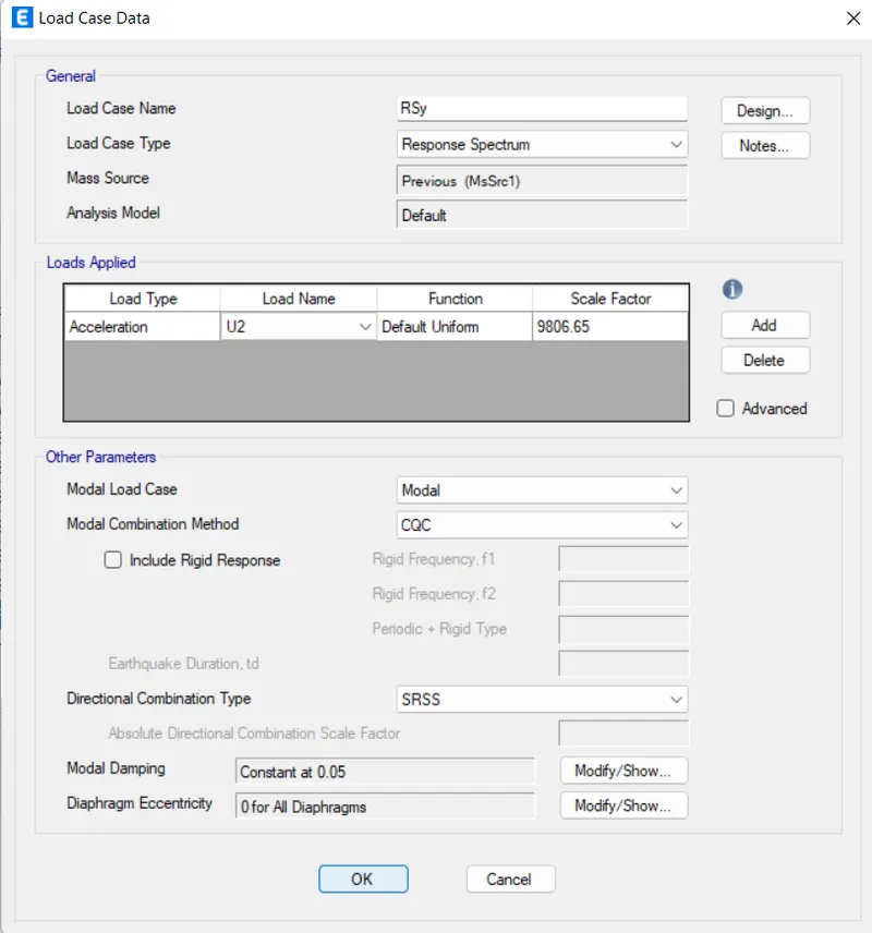
- And now add Response spectrum in load cases as RSx and RSy.
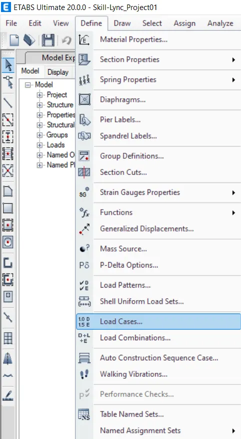
- And in order to assign the response spectrum just go to the Define tab click on that option then there will be a drop-down list and in that list there will be an option called Load Cases click on that option just as shown in the below given image:
- After that there will be another dialouge box named as the Load cases and in that dialouge box there will be an option named as the Add New Case click on that just as shown in the below given images:

- After that there will be another dialouge box named as the Load Case Data and in that dialouge box fill all the necessary data just as shown in the below given image:
RSx:

RSy:
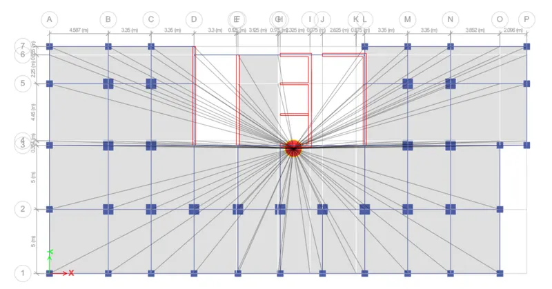
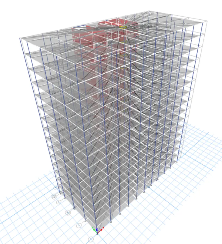
- And now we will be assigning the Diaphragm.
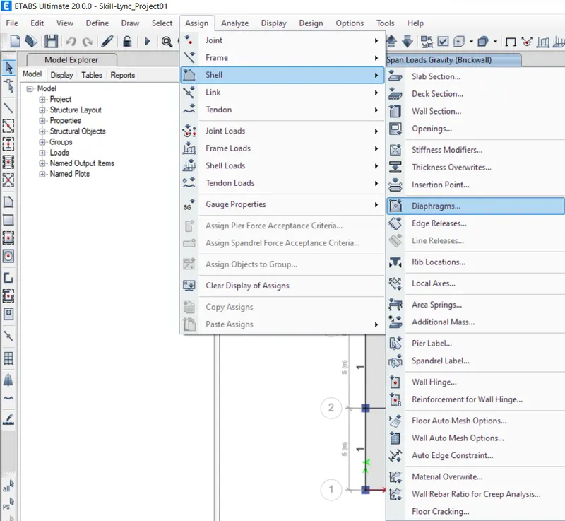
- So in order to assign the diaphragm,we need to go to the Assign tab click on that option and then there will be a drop-down list and in that list there will be an option called Shell click on that option after that there will be another drop-down list and in that list there will be another option called Diaphragms just click on that option just as shown in the below given image:
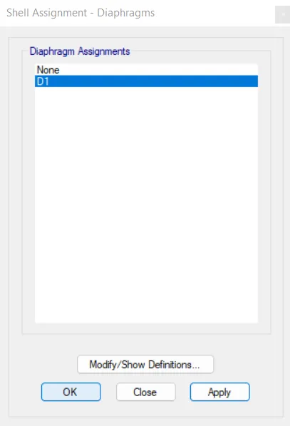
- After that there will be another dialouge box named as the Shell Assignment-Diaphragms and in that dialouge box there will be an option D1 just click on that option then there will be another option called Apply just click on the tab and then OK just as shown in the below given image:
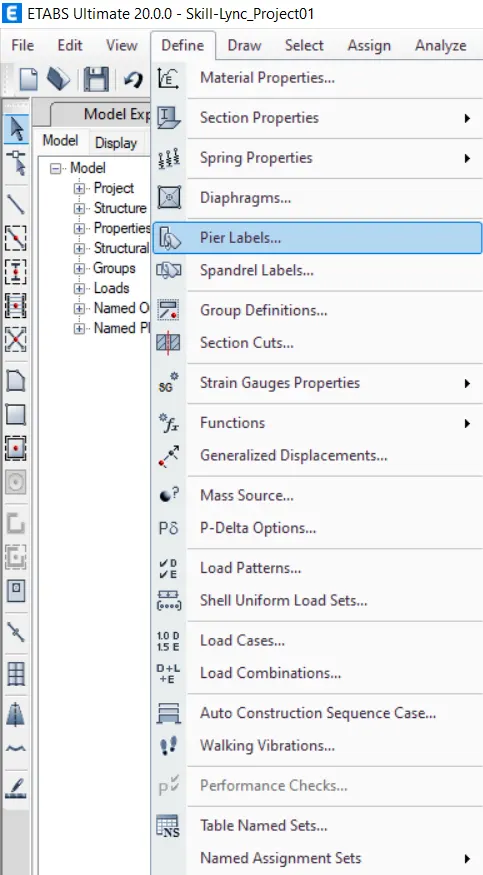
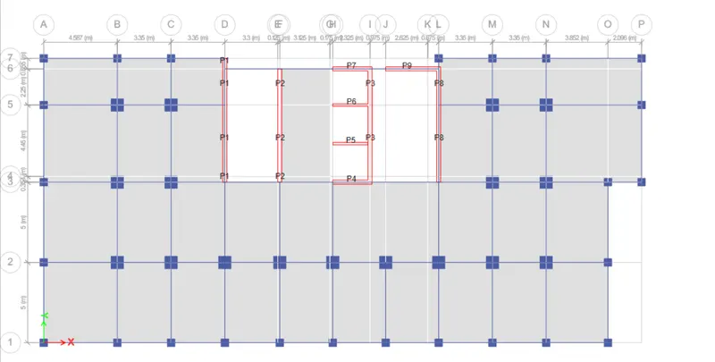
- After this we will be assigning the Pier labels.
- And in order to assign the pier labels,go to the Define tab click on that option then there will be a drop-down list and in that list there will be an option called Pier Labels just click on that option just as shown in the below given image:
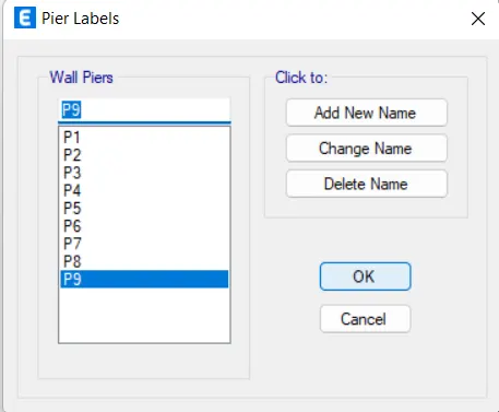
- After that there will be another dialouge box named as the Pier Labels and in that dialouge box fill out all the necessary details just as shown in the below given image:
- After this assign the support condition as fixed support just as shown in the below given image:
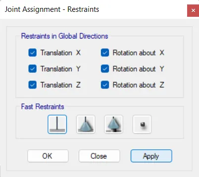
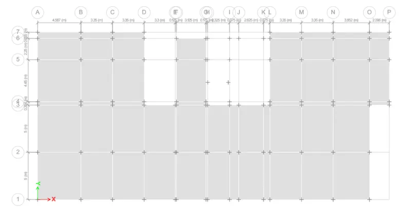
- Create service & ultimate load combinations as per IS 456:2000:
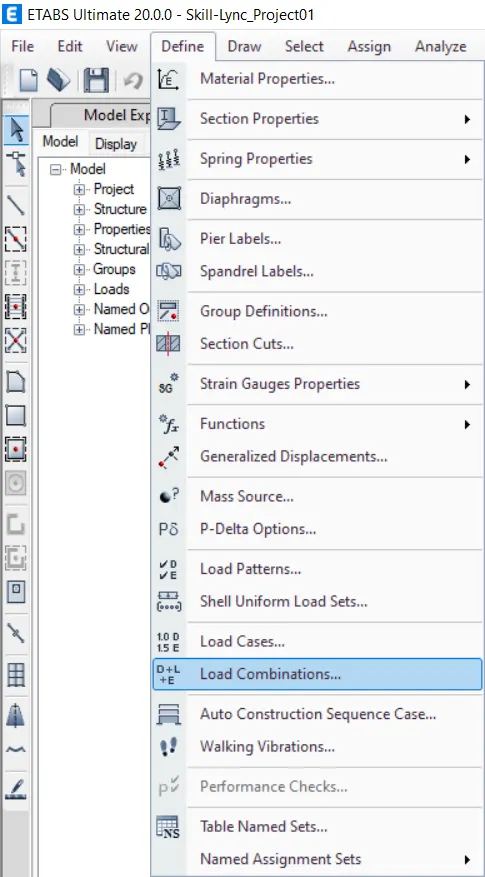
- And now we have to assign the the service and the ultimate load combinations as per the IS 456:2000.
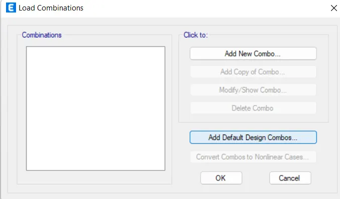
- So, in order to assign the load combinations just go to the Define tab click on that option then there will be a drop-down list and in that list there will be another option named as the Load combinations click on that option too just as shown in the below given image:
- After this there will be another dialouge box named as the Load Combinations and in that dialouge box there will be another option called Add Default Design Combos click on that option just as shown in the below given image:
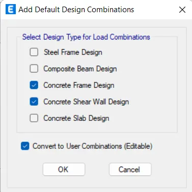
- And after that there will be another dialouge box named as the Add Default Design Combinations click on the options just as shown in the below given figure and then click on the OK:
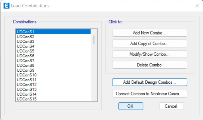
- After this there will be Auto-generated codes according to the IS 456:2000 just as shown in the below given image:
- Now we have to checked the model and in order to check the model we need to go to the Analyze tab just click on that option then there will be a drop-down list and in that list and then there will be another option called Check model just click on that option just as shown in the below given image:
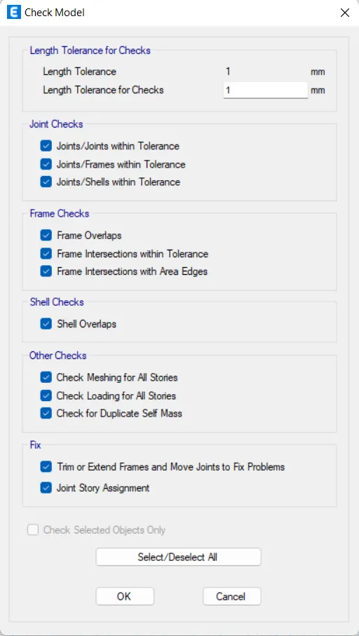
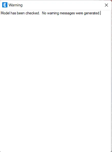
- Now the model is checked without any warnings just as shown in the below given image:
- After that we will be doing the Run-Analysis because we have already provided the all inputs.
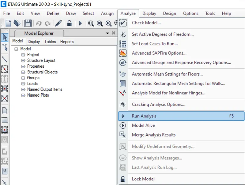
- So in order to do the analysis,we need to go to the Analyze tab click on that option then there will be another drop-down list and in that list there will be another option named as the Run Analysis or just press F5 just as shown in the below given image:
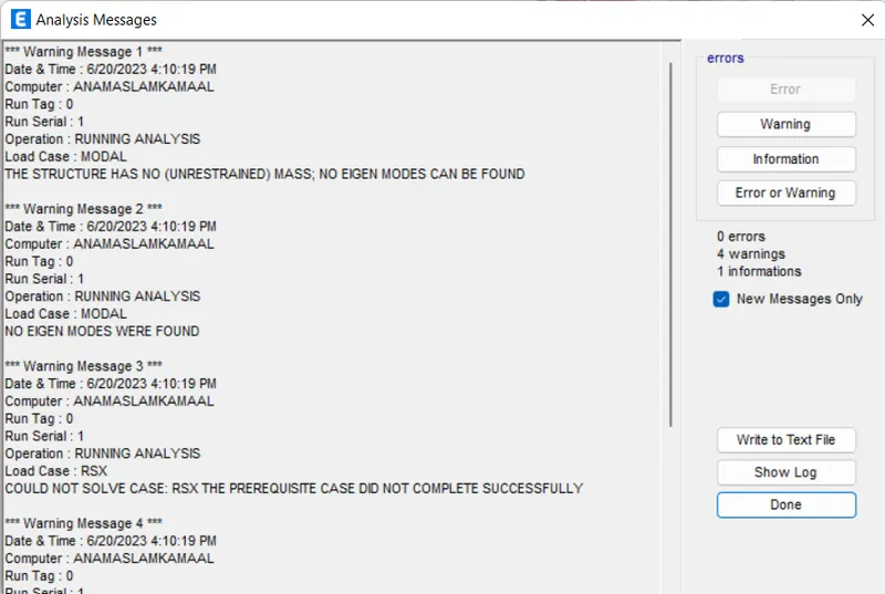
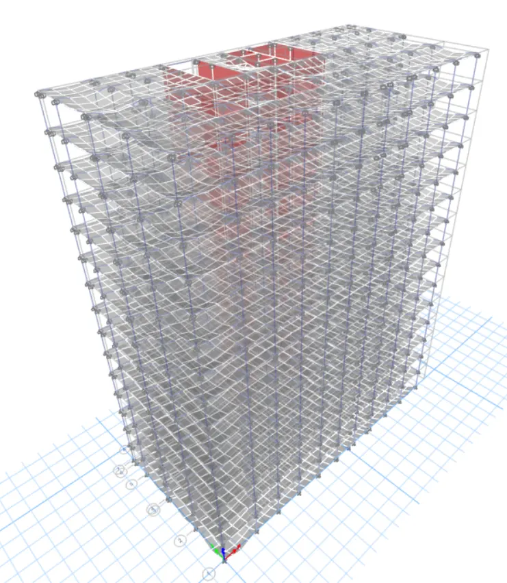
- Below is the result after the analysis:
c. Structural Analysis:
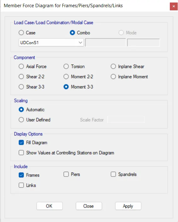
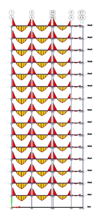
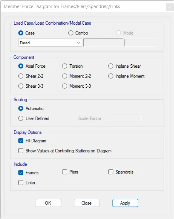
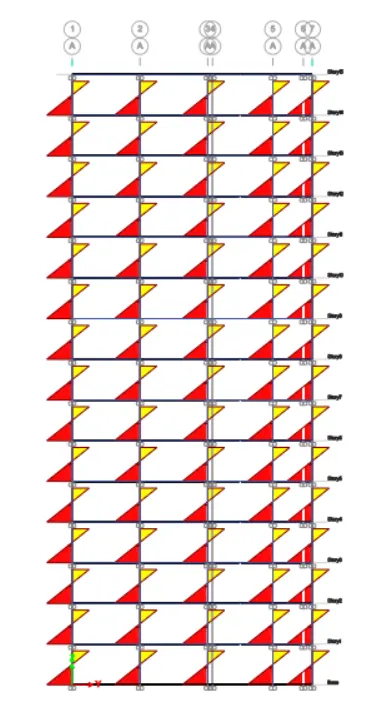
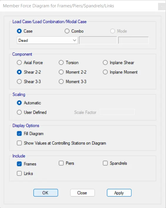
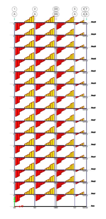
- Obtain the shear force & moment diagram for the floor beams & columns.
- Check the gravity load path in the structure if it follows the designer’s intent.
- Perform quick hand calculations to confirm the base reactions for the gravity load cases.
- Obtain the shear force & moment diagram for the floor beams & columns:
- Perform quick hand calculations to confirm the base reactions for the gravity load cases:
Slab thickness = 150mm
Beam size= 300mm X 300mm
Live load = 2 kN/sq.m.
Floor finish= 1.5 kN sq.m.
Brickwall load= 3.5 kN/m.
Self weight of slab = 0.150 X 25 KN/m2 = 3.75 kN/sq.m.
Total load in slab = 3.75 + 2 + 1.5 = 7.25 kN/sq.m.
Load in each end of B1:-
Area 2(Trapezoidal area):
A1 = 1/2 * (1.529 + 4.587) * 2.5 = 7.645 sq.m.
Bay width of B2 = A1/L or L/4
= 7.645/4.587 = 1.66 m or 1.14m
UDL transferred from slab-1 to Beam-2 = B.W X Slab-2 load
= 1.66 X 7.25 = 12.035 kN/m
Beam-1 Self weight = 0.4*0.4*25 = 4 kN/sq.m.
Total UDL on B1 = 4 + 12.035 + 3.5 = 19.535 kN/m.
Total load on B1 = (19.535 X 4.857) = 89.607 kN.
Load on each end for B1 is 44.804 kN.
Load in each end of B2:-
Area 2(Triangular area)
A2 = [1/2 * 2.5 * 1.529 ]* 2 = 3.82 sq.m.
Bay width of B2 = A2/L or L/4
= 3.82/5 = 0.764 m or 1.25m
UDL transferred from slab-2 to Beam-2 = B.W X Slab-2 load
= 1.25 X 7.25 = 9.0625 kN/m.
Beam-1 Self weight = 0.4*0.4*25 = 4 kN/sq.m.
Total UDL on B2 = 4 + 9.0625 + 3.5 = 16.5625 kN/m
Total load on B2 = (16.5625 X 5) = 82.82 kN
Load on each beam B2= 41.41 kN
Total axial load on column C1 = 44.804 + 41.41 = 86.21 KN
Total axial load on C1 column = Number of floor X Load in first floor Column C1
= 15 X 86.21 = 1293.15 kN.
d. Design of structural members
- Select appropriate parameters for the design of the members.
- Interpret the design results.
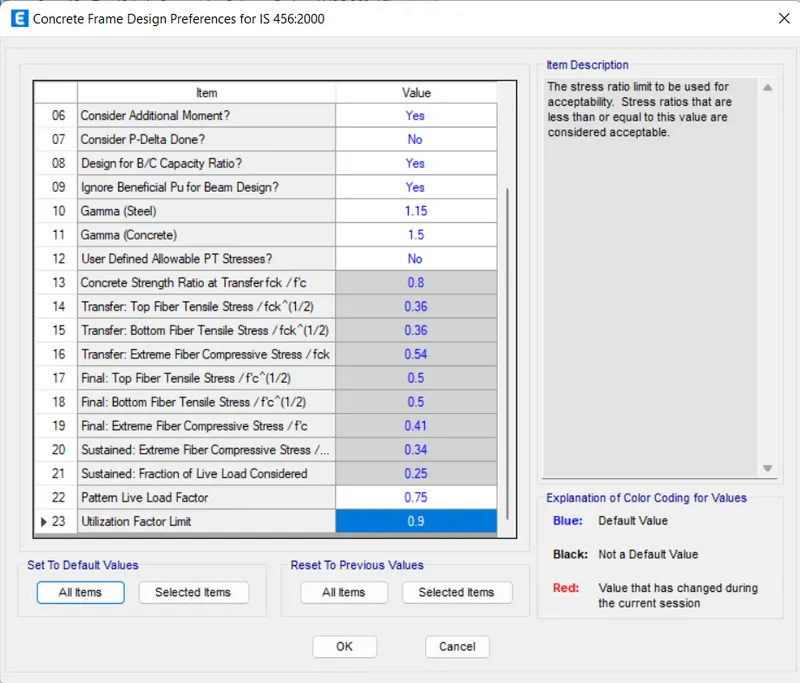
- Re-design and restrict the member utilization within 0.9.
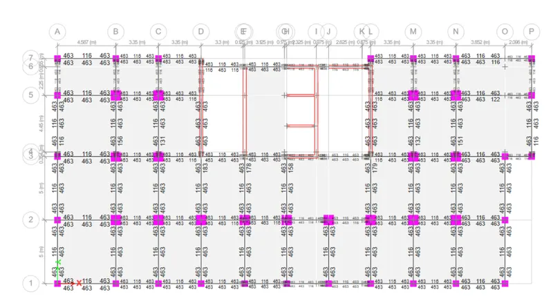
- Identify the reinforcement requirements for each structural member.
- Select appropriate parameters for the design of the members:
- Re-design and restrict the member utilization within 0.9:
- Interpret the design results:
Beam Longitudinal Reinforcement Details:
- Below are the attachments of the following files:
- ETABS file in .e2k format.
- A comprehensive project report from the ETABS software as PDF file.