Project-1: Modelling an electric Car with Li-ion battery
Project-1: Modelling an electric Car with Li-ion battery
QUESTION:
Create a MATLAB model of electric car which uses lithium ion battery and suitable motor. Choose suitable blocks from Simscape or Powertrain block set. Implement the vehicle speed control using PI controller and generate brake and accelerator commands. Avoid using readymade driver block for speed control.
Prepare a report about your model including following:
Objectives, System level configurations, Model parameters, Results, Conclusion.
(Note- The simulink model file should be compulsorily attached)
ANSWER:
INTRODUCTION:-
The electric vehicle is a vehicle, which uses one or more electric motors for propulsion. Depending on the type of the vehicle motion may be provided by rotary motor or by a linear motor (in the tracked vehicle). The electricity stored in battery-powered by electric motor & battery can be charged by plugging it in the grid, like our phone.
According to the degree of electricity used, an electric vehicle is divided into 3 categories-BEV, PHEV & HEV.
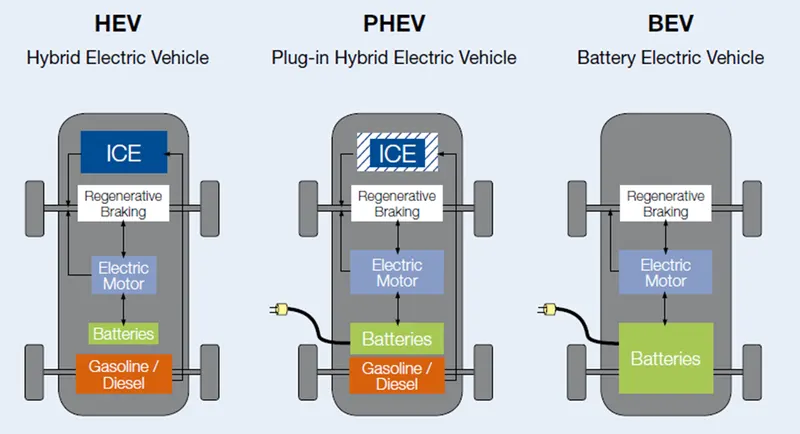
Battery Electric Vehicles (BEV)
BEVs are fully electric vehicles with rechargeable batteries with no engine. It stares power in battery pack & this power is used to run the vehicle & other peripherals BEVs are charged by electricity from external source BEVS don't emit any hazardous emissions. Some most famous examples of these types of cars are BMW 13, Tesla Model, 3. Kia Soul Toyota Rav4 etc.
Plug-In Hybrid Electric Vehicles (PHEV)
These types of vehicles are propelled by motor and gasoline engine Battery is charged with regenerative braking & it can be charged with external source PHEVS can go from 10-40 miles before the assistance of engine Examples PHEVs-Chevy Volt. Audi A3 E-Tron BMW i8. Toyota Prius etc
Hybrid Electric Vehicle (HEVs)
HEVS are powered with both gasoline & electricity. The battery can be charged with regenerative power only. The motor supplies power from starting, the engine takes care of high speed & heavy load. Controller used to ensure the best economy, HEVs are-Honda Civic Hybrid, Toyota Prius Hybrid, Toyota Camry Hybrid.
OBJECTIVES:
- Create a MATLAB model of an electric car that uses a lithium-ion battery and a suitable motor. Choose sustainable blocks from Simscape or Powertrain block set
- Implement the vehicle speed control using Pi controller and generate brake and accelerator commands Avoid using readymade driver black for speed control
Prepare a report about your model including the following:
# Objectives
# System-level configurations
# Model parameters
# Results
# Conclusion
component of the electrical vehicle :
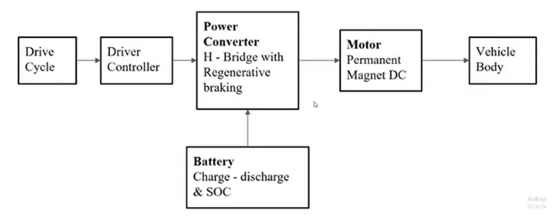
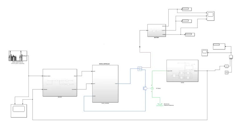
MATLAB Model of Electric Car which uses Li-ion Battery and Suitable Motor:
Battery:-
- Most electric vehicles use lithium-ion batteries (Li-Ions or LIBs). Lithium-ion batteries have a higher energy density, longer life span and higher power density than most other practical batteries. Complicating factors include safety, durability, thermal breakdown and cost. Li-ion batteries should be used within the safe temperature and voltage ranges in order to operate safely and efficiently.
- Increasing the battery's lifespan decreases effective costs. One technique is to operate a subset of the battery cells at a time and switching these subsets.
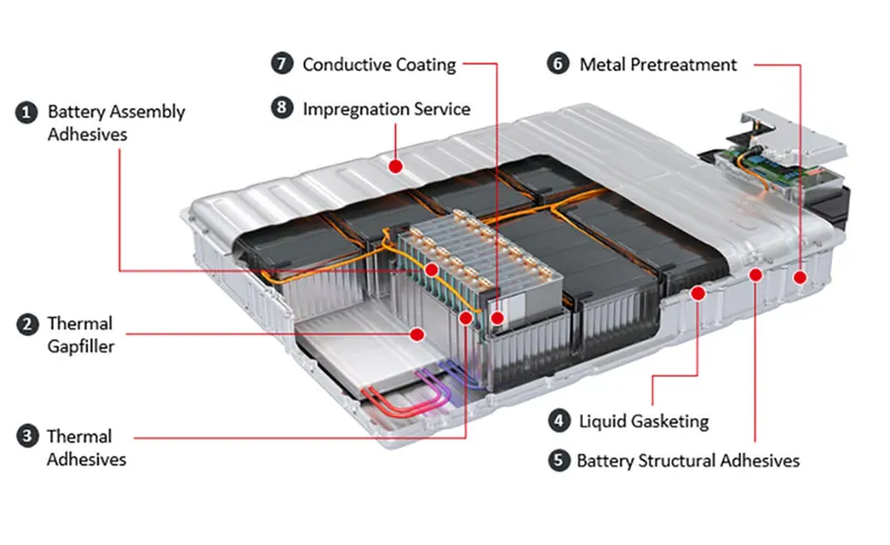
- In the past, nickel-metal hydride battery batteries were used in some electric cars, such as those made by General Motors. These battery types are considered outdated due to their tendencies to self-discharge in the heat. Furthermore, a patent for this type of battery was held by Chevron, which created a problem for their widespread development. These factors, coupled with their high cost, have led to lithium-ion batteries leading as the predominant battery for EVs.
- The prices of lithium-ion batteries are constantly decreasing, contributing to a reduction in the price of electric vehicles
Battery and SOC System matlab model :-
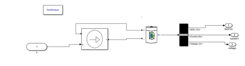
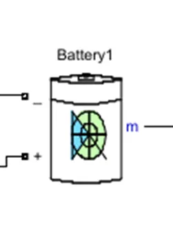
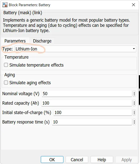
Battery:- Implements a generic battery model for most popular battery types. Temperature and ageing (due to cycling) effects can be specified for Lithium-Ion battery type
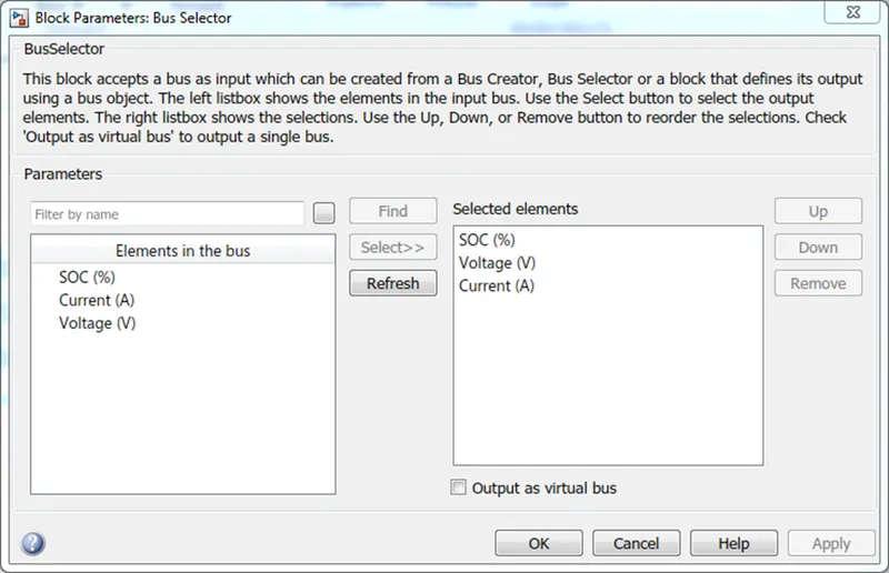
Bus selector
Vehicle body and tire subsystem:-
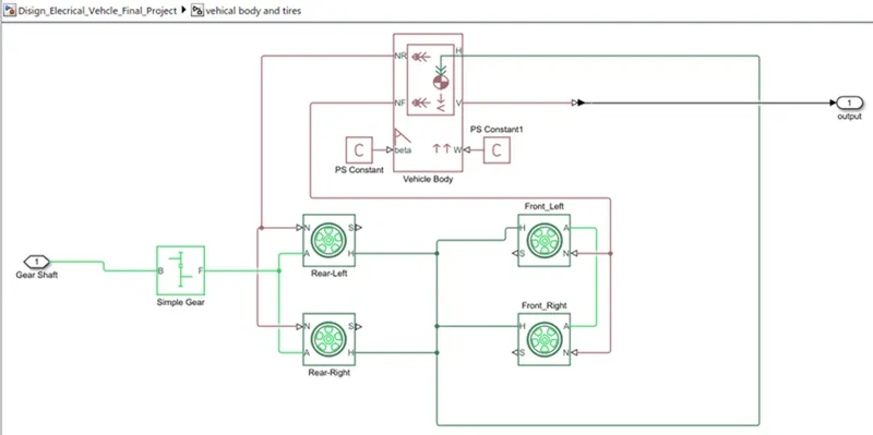
- Represents a two-axle vehicle body in motion.
- Accounts for body mass, aerodynamic drag. grade, externally defined mass and centre of gravity of the vehicle body.
o Input Ports:
W=Wind Velocity in m/s
beta=Grade angle in radians
o Output Ports:
V=Velocity in m/s
NR=Normal force on Rear Axle (N)
NF=Normal Force on Front Axle (N)
Vehicle Body Parameters:
- Vehicle body mass, Centre of gravity distance values and aerodynamic drag
variables are modified. Pitch dynamics are kept ON with other variable values as default values.
tire:
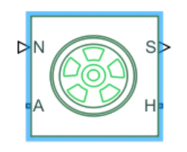
The vehicle is assumed to be front axle is driven (4 wheels- 2 on each axle).
The wheels are modelled using simple Tire (Magic formula) Simulink blocks.
The block can model tire dynamics under constant or variable contact surface
conditions.
- Input Port:
N=Normal force acting on the tire, positive when force is acting downwards/towards the contact surface.
- Output Port:
S=Slip value is relative to tire and surface of contact.
- Conserving Ports:
H=represents wheel hub which transmits thrust generated by the wheel to the body of the vehicle.
A=represents the axle on which the tires are mounted.
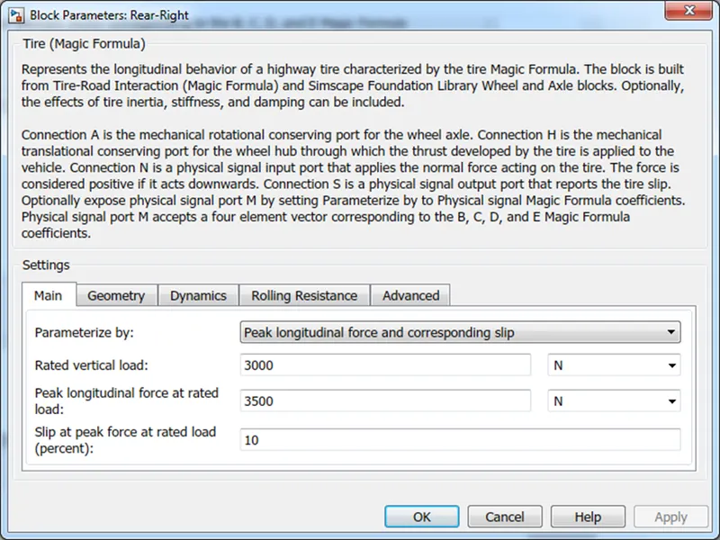
- The tires are parameterized by Peak longitudinal force and corresponding slip
- The other block parameters such as rated vertical load, peak longitudinal force at rated load and slip at peak force at rated load - are kept with their default values.
Gear:
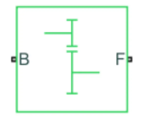
A simple gear block is used to connect the motor to the rear axle of the vehicle.
It represents the gearbox that connects the input shaft to the base gear and output from the follower gear.
Conserving Ports:
B=port associated with an input shaft (motor shaft)
F=port associated with the output shaft (axle/ differential)
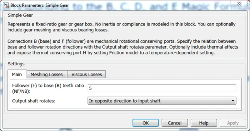
Simple Gear Parameters:
Gear ratio and output direction are modified. Meshing loss is kept constant and gear is having a constant efficiency throughout the simulation.
Viscous losses and faults are kept at default conditions
Vehicle Body:-
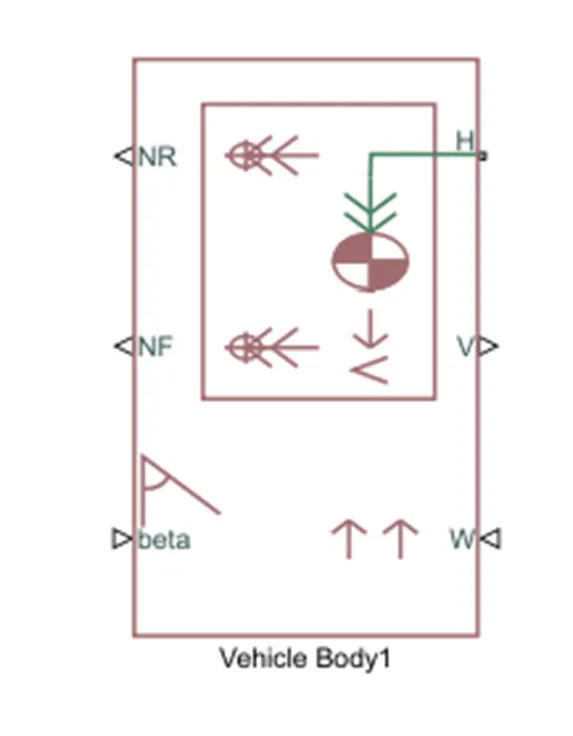
- This block basically represents a two-axle vehicle body in longitudinal motion. The block accounts for - body mass, aerodynamic drag, road incline, weight distribution between axles due to acceleration road profile.
- Here, connection H is the mechanical translational conserving port hub.
- NF & NR correspond to the output ports for normal reaction forces on the front axle and rear axle wheels respectively.
- Connection V represents the actual output translational velocity of the vehicle.
- beta is the road inclination angle & W corresponds to the headwind speed (headwind direction opposite to that of the vehicle).
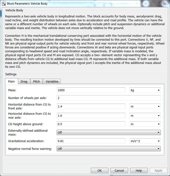
- The gross weight is given to be 1000 kg
- The geometric parameters of the vehicle are given as
Power and Motor Controlled Subsystem:-
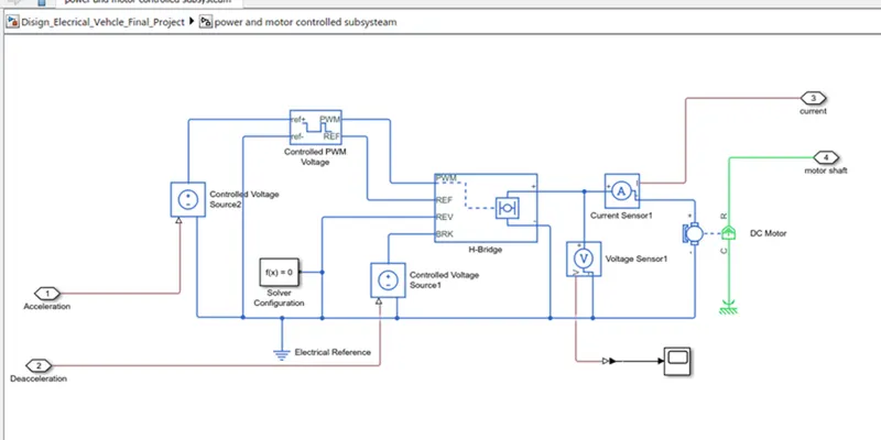
H-Bridge:-
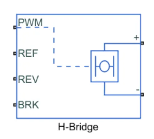
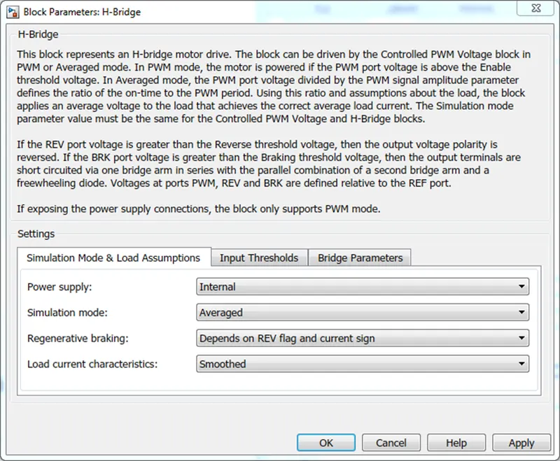
The H-Bridge helps in controlling the power that is input according to the requirement. The output provided is converted voltage as per the controlled parameters.
2 D.C Motor:-
This is the DC Motor which would give rotational power to the wheels and become the sole power generation source.
The DC Motors terminals are connected as mentioned below.
+ =Electrical signal to the motor Positive Terminal
- =Electrical signal to the motor Negative Terminal
R=Casing of the Motor connected with the Mechanical Rotational Reference Block
C=Rotor Case connected to the Mechanical Rotational reference
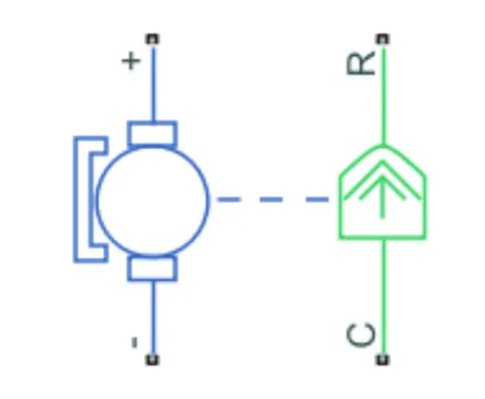
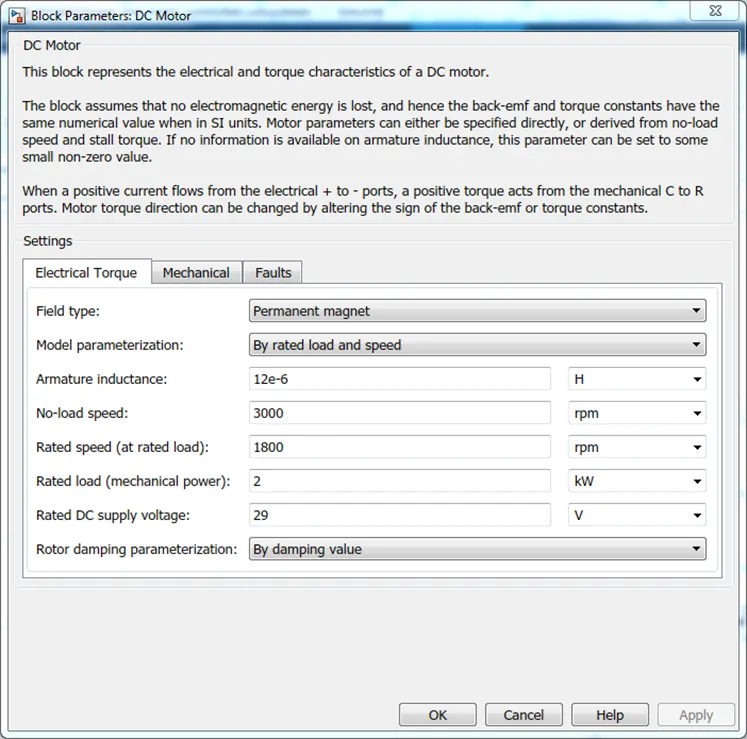
The parameter considered is, The Armature inductance is as default, varied the changes in the No-Load Speed 3000 rpm, the rated speed 1800 rpm, the Rated Load at 2kW, and the Rated DC Supply Voltage 29 V. All other parameters are as default
Controlled PWM Voltage:
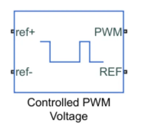
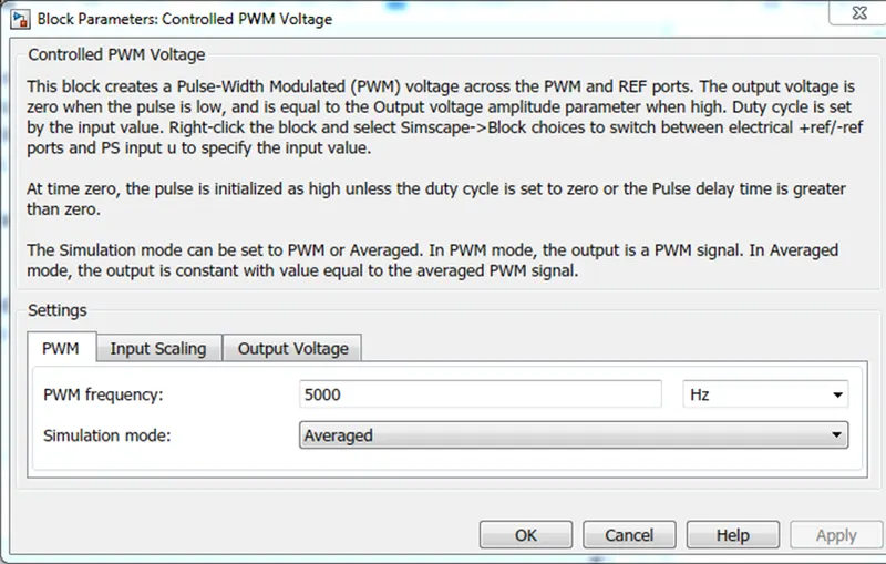
The Controlled PWM Voltage Block helps in keeping the Modulated Pulses as per the required pulses. So that the operations happen smooth and higher variations are not observed.
The Ports are connected as follows.
PWM=PWM connected directly to the H-Block
REF=REF connected directly to the H-Block
ref+ = Reference Positive connected with Driver Model ith the Acceleration Commands from the
ref- =Reference Negative connected with the Deceleration Commands from the Driver Model
Note: The parameters are set as default.
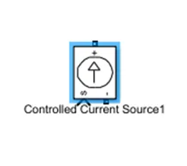
controlled Current Source:-
a controlled current source is connected to the lithium battery. this controlled current source provided will initiate the flow of current from the battery to the motor and during regenerative braking from the motor to the battery.
DRIVER BLOCK:-
- The Driver block is basically a controller for the vehicle, it controls the acceleration, and braking of the vehicle. The block is implemented with a PID controller which is basically the main controller in the whole drive cycle
- The PID controller works as closed-loop speed control, it takes the input as a reference speed and connects the error generated by the vehicle speeds
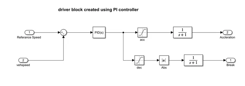
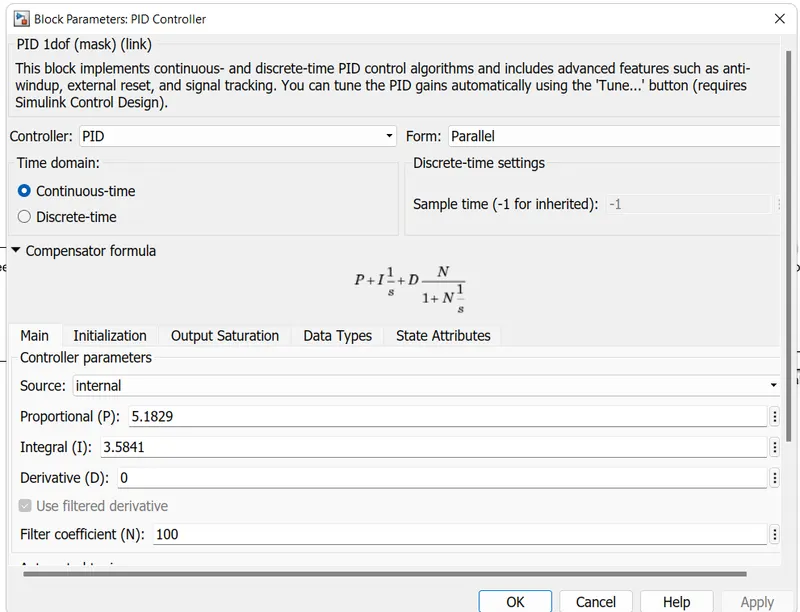
- PID controller is tuned for adequate acceleration and deacceleration commandant is done by limiting its output to upper and lower saturation Separating the output of the PID to accelerate and deacceleration command
- We Tune a situation block for each command for acc command we use an upper saturation value and for the deaccelerate command, we use a lower saturation value
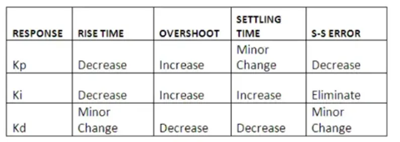
- Tuning is Proportional, derivative and integral values we should be able to track the reference speed. The below table gives us an idea for the manual tuning of the controller
Reference Velocity (Drive Cycle):
- The Drive Cycle Source block is used to provide the reference speed for the simulation.
- It generates a standard or user-specified longitudinal drive cycle.
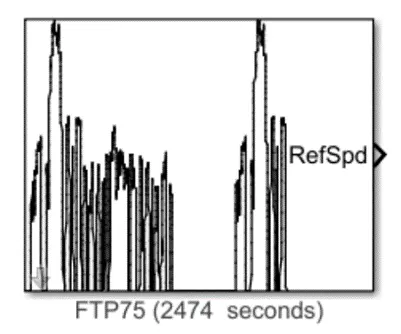
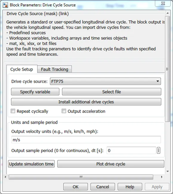
in this selected driving cycle is FTP75 among so many drive cycle cycle
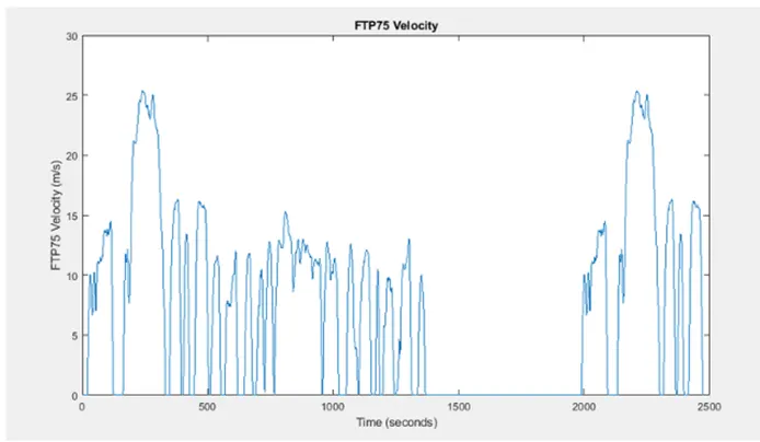
Fig. drive cycle FTP75
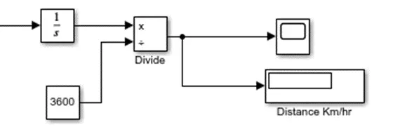
Distance in km/hr:-
SOLVER CONFIGURATION:-
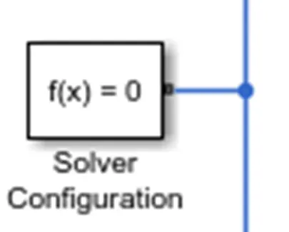
A Solver Configuration is added to ensure proper solving of the mathematical equations by the model.
RESULTS:-
the vehicle run for the 4.163km/hr as shown in the graph below
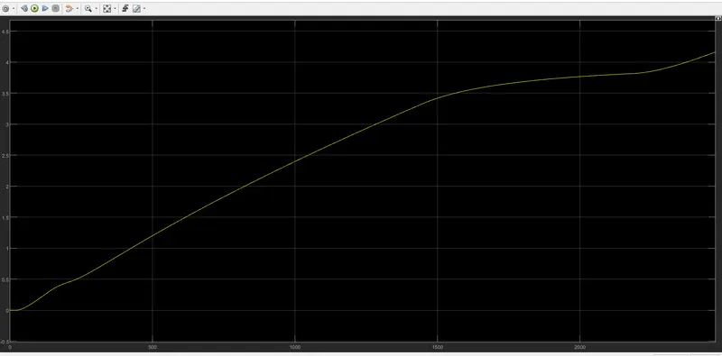
the running condition of the vehicle is linear till the 3.5 then some amount of dcreases inthe graph we have seen between the 3.5 to 4
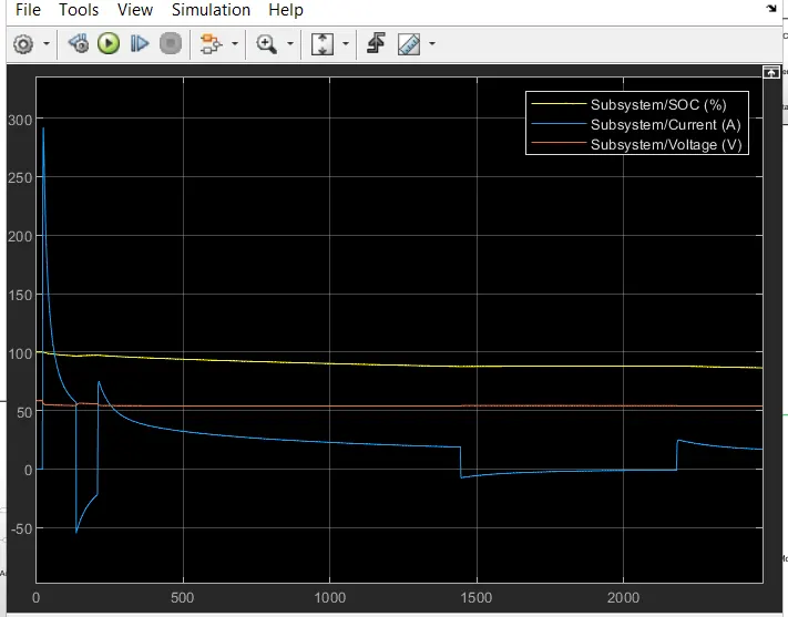
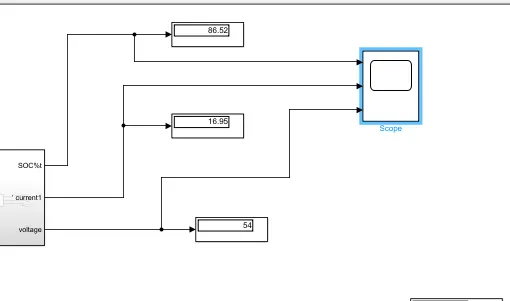
the value we get from the battery specification i.e SOC ;CURRENT and VOLTAGE drawn by the battery
the state of charge is linearly decreases as the the distance increases at finally we get 86.52 SOC
also we have get to see that the current at the starting is preciously high drawn by the battery almost it reaches to 280A at the end of the simulation we get approx.16A
speaking about the voltage we get decreasing voltage i.e 54v
by seeing the graph the we dont"t found any ripple in the voltage and athe the starting the current drawn by the battery is much high but the voltage is linearly decreases.
vehicle speed vs reference speed :
The simulation was run for about 2500 sec and we have obtained the result shown above.
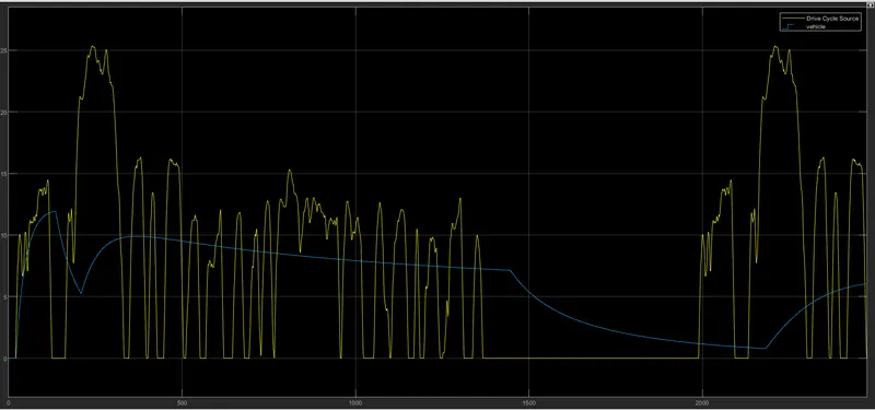
The blue line is a graph of the drive cycle source and the yellow line shows the corresponding velocity ;our graph of vehicle speed not follow the reference speed.
CONCLUSION:
from the above model and from the assumed parameters we found that the velocity of an electric vehicle is 4.163 km with 100ah capacity and 50 v nominal voltage and also the variation of SOC and the battery current and battery voltage is also studied.