Project-1: Modelling an electric Car with Li-ion battery
Create a MATLAB model of electric car which uses lithium ion battery and suitable motor. Choose suitable blocks from Simscape or Powertrain block set. Implement the vehicle speed control using PI controller and generate brake and accelerator commands. Avoid using readymade driver block for speed control.
Objectives
To model an electric car with a Li-ion battery, you would need to consider several factors such as the battery capacity, motor efficiency, driving range, charging time, and more. Here are the steps you can follow to model an electric car with a Li-ion battery:
-
Define the specifications of the car and the battery: This includes the battery capacity, voltage, energy density, and other relevant parameters.
-
Calculate the energy required for the car to travel a certain distance: The energy required depends on the weight of the car, the aerodynamics, the rolling resistance, and the efficiency of the motor.
-
Calculate the driving range of the car: The driving range is the distance the car can travel on a single charge of the battery. This depends on the battery capacity, energy density, and the energy required to travel a certain distance.
-
Calculate the charging time: The charging time is the time required to charge the battery from empty to full. This depends on the charging rate, which is limited by the charging infrastructure and the battery capacity.
-
Simulate the performance of the car: You can use a simulation software to model the behavior of the car and the battery under different conditions. This can help you optimize the design and performance of the car.
-
Evaluate the environmental impact: You can also evaluate the environmental impact of the car by calculating the carbon emissions, energy consumption, and other factors. This can help you identify areas where you can improve the sustainability of the car.
Overall, modelling an electric car with a Li-ion battery requires a comprehensive understanding of the battery technology, motor efficiency, and other factors that affect the performance and sustainability of the car. By carefully analyzing these factors, you can design an electric car that is efficient, reliable, and environmentally friendly.
- System level configurations
Electric vehicles are by many seen as the cars of the future as they are very efficient, produce
no local pollution, are silent, and can be used for power regulation by the grid operator. In order to be able to estimate the performances of an electric vehicle it is very important to have a proper model of it. The electric vehicle model is very complex as it contains many different components. Each component needs to be modelled properly in order to prevent wrong conclusions. The design or rating of each component is a difficult task as the parameters of one component affect the power level of another one. There is therefore a risk that one component is rated inappropriately which may make the vehicle unnecessary expensive or inefficient. In this paper a new design model of the electric vehicle is presented. This model is based on the combination of Modelica with ModelCenter. Modelica has been used to model and simulate the electric vehicle and ModelCenter has been used to optimize the design variables. The model ensures that the requirements related to driving distance and acceleration are fulfilled.
Electric vehicles consists of an electric motor that is powered by a battery pack. The main advantage of electric vehicles is that they emit zero emissions and are eco-friendly. They also do not consume any fossil fuels, hence use a sustainable form of energy for powering the car. The main components of electric vehicles are :
- Traction battery pack
- DC-DC Converter
- Electric motor
- Power inverter
- Charge Port
- Onboard charger
- Controller
- Auxiliary batteries
- Thermal system (cooling)
- Transmission
1.Traction battery pack
Traction battery pack is also known as Electric vehicle battery (EVB) . It powers the electric motors of an electric vehicle. The battery acts as an electrical storage system. It stores energy in the form DC current. The range will be higher with increasing kW of the battery. The life and operation of the battery depends on its design. The lifetime of a traction battery pack is estimated to be 200,000 miles.
2. DC-DC Converter
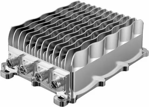
The traction battery pack delivers a constant voltage. But different components of the vehicle has different requirements. The DC-DC convertor distributes the output power that is coming from the battery to a required level. It also provides the voltage required to charge the auxiliary battery.
3.Electric motor
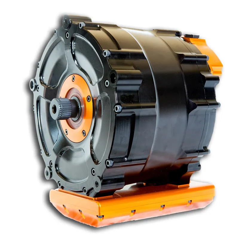
Electric traction motor is the main components of electric vehicle. The motor converts the electrical energy into kinetic energy. This energy rotates the wheels. Electric motor is the main component that differentiates an electric car from conventional cars. An important feature of an electric motor is the regenerative braking mechanism. This mechanism slows down the vehicle by converting its kinetic energy into another form, and storing it for future use. There are basically two types of motors DC and AC motors.
Related article
Detailed working of an electric motor
4.Power Inverter
It coverts DC power from the batteries to AC power. It also converts the AC current generated during regenerative braking into DC current. This is further used to recharge the batteries. The inverter can change the speed of the
5. Charge Port
The charge port connects the electric vehicle to an external supply. It charges the battery pack. The charge port is sometimes located in the front or rear part of the vehicle
6.Onboard charger
Onboard charger is used to convert the AC supply received from the charge port to DC supply. The on board charger is located and installed inside the car. It monitors various battery characteristics and controls the current flowing inside the battery pack.
7.Controller
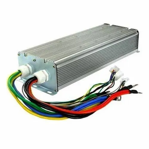
Power electronics controller determines the working of an electric car. It performs the regulation of electrical energy from the batteries to the electric motors. The pedal set by the driver determines the speed of the car and frequency of variation of voltage that is input to the motor. It also controls the torque produced.
8.Auxiliary batteries
Auxiliary batteries are the source of electrical energy for the accessories in electric vehicles. In the absence of the main battery, the auxiliary batteries will continue to charge the car. It prevents the voltage drop, produced during engine start from affecting the electrical system.
9. Thermal system(cooling)
The thermal management system is responsible for maintaining an operating temperature for the main components of an electric vehicle such as, electric motor, controller etc. It functions during charging as well to obtain maximum performance. It uses a combination of thermoelectric cooling, forced air cooling, and liquid cooling.
10. Transmission
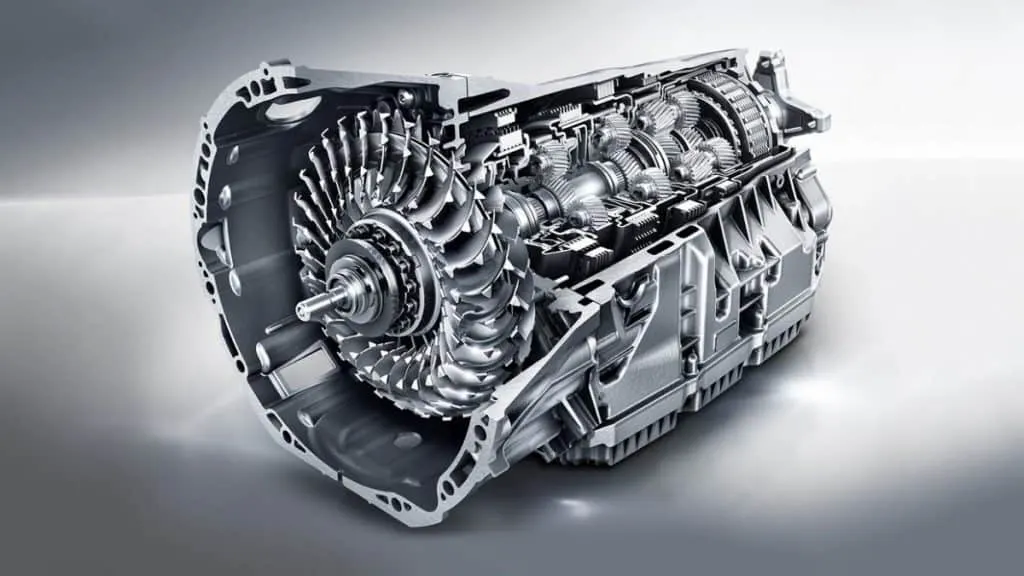
It is used to transfer the mechanical power from the electric motor to the wheels, through a gearbox. The advantage of electric cars is that they do not require multi-speed transmissions. The transmission efficiency should be high to avoid power loss.
2.Model parameters
complete Electric Vehicle Design
2.Model parameters
complete Electric Vehicle Design
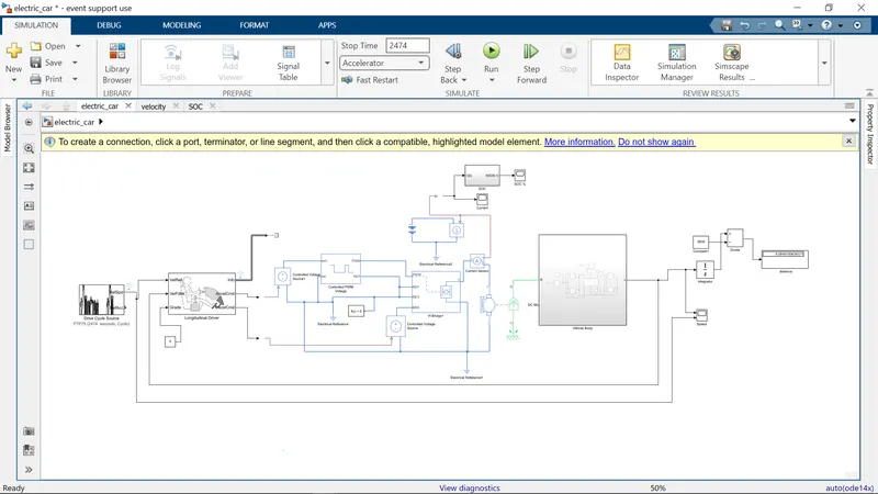
in below You can see the each Model Explanation.
Vehicle Body
To model a vehicle's body, we need to first add the vehicle body block and this is shown below:
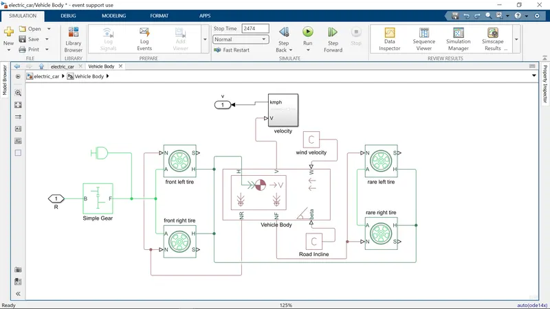
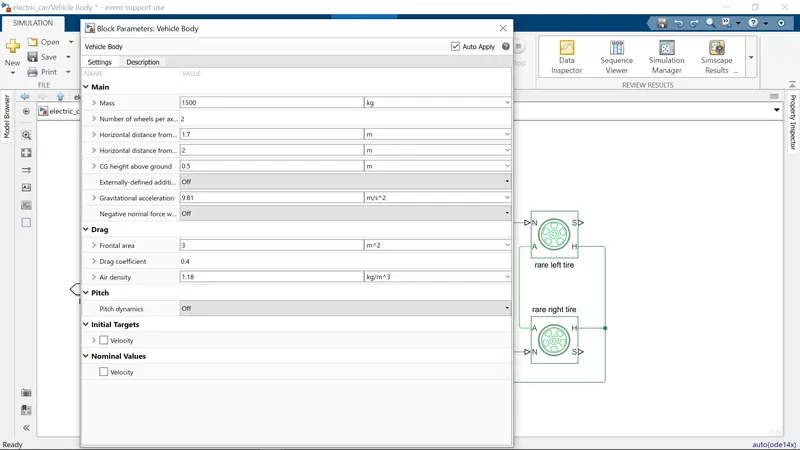
If we double click the vehicle body block, we can see and modify its parameters and this is shown In the Right Side image
Represents a two-axle vehicle body in longitudinal motion. The block accounts for body mass, aerodynamic drag, road incline, and weight distribution between axles due to acceleration and road profile. The vehicle can have the same or a different number of wheels on each axle. Optionally include pitch and suspension dynamics or additional variable mass and inertia. The vehicle does not move vertically relative to the ground.
Connection H is the mechanical translational conserving port associated with the horizontal motion of the vehicle body. The resulting traction motion developed by tires should be connected to this port. Connections V, NF, and NR are physical signal output ports for vehicle velocity and front and rear normal wheel forces, respectively. Wheel forces are considered positive if acting downwards. Connections W and beta are physical signal input ports corresponding to headwind speed and road inclination angle, respectively. If variable mass is modeled, the physical signal input ports CG and M are exposed. CG accepts a two- element vector representing the x and y distance offsets from vehicle CG to additional load mass CG. M represents the additional mass. If both variable mass and pitch dynamics are included, the physical signal port J accepts the inertia of the additional mass about its own CG.
This block contains 6 ports which can be used to model the various aspects of the vehicle body. The ports are mentioned and elaborated below:
- H - This stands for 'Hub' and is used to connect the hubs of the wheels to the main body of the vehicle.
- V - This is a physical signal output port which stands for 'Velocity' and is used to output the speed/velocity at which the vehicle is moving at.
- W - This is a physical signal input port and allows us to model a 'headwind' acting on the vehicle by giving a speed for it.
- NR - This is a physical signal output port to model the rear wheel normal forces.
- NF - This is a physical signal output to model the front wheel normal forces.
- beta - This is a physical signal input port and allows us to model the vehicle on an inclination angle to create the effect of a hill climbing force.
Tires
Represents the longitudinal behavior of a highway tire characterized by the tire Magic Formula. The block is built from Tire-Road Interaction (Magic Formula) and Simscape Foundation Library Wheel and Axle blocks. Optionally, the effects of tire inertia, stiffness, and damping can be included.
Connection A is the mechanical rotational conserving port for the wheel axle. Connection H is the mechanical translational conserving port for the wheel hub through which the thrust developed by the tire is applied to the vehicle. Connection N is a physical signal input port that applies the normal force acting on the tire. The force is considered positive if it acts downwards. Connection S is a physical signal output port that reports the tire slip. Optionally expose physical signal port M by setting Parameterize by to Physical signal Magic Formula coefficients. Physical signal port M accepts a four element vector corresponding to the B, C, D, and E Magic Formula coefficients.
The tires used in this EV model are the 'magic formula' tires. There are several tire blocks that can be used for modelling a vehicle but I have used the magic formula ones because it allows us to model the longitudinal behavior of vehicle tires on highways. They also allow us to model extra effects such as tire inertia, stiffness which allow for greater accuracy of real world conditions. The magic formula tire block is shown below:
Double clicking the magic formula tire block takes us to its parameters.
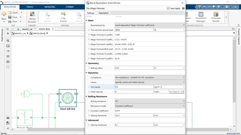
We can see that it has 4 ports and they are:
- N - This port stands for 'Normal' and is the physical signal input port for the normal force acting on the tire and is considered positive in the downwards direction.
- S - This port stands for 'Slip' and is the physical signal output port is that reports the slip acting on the tire.
- A - This port stands for 'Axle' and is the mechanical rotational conserving port for the wheel axle.
- H - This port stands for 'Hub' and is the mechanical translational conserving port for the wheel hub through which the thrust developed by the tires is applied to the vehicle body.
Gear
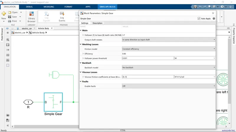
Represents a fixed-ratio gear or gear box. No inertia or compliance is modeled in this block. You can optionally include gear meshing, backlash, and viscous bearing losses.
Connections B (base) and F (follower) are mechanical rotational conserving ports. Specify the relation between base and follower rotation directions with the Output shaft rotates parameter. Optionally include thermal effects and expose thermal conserving port H by setting Friction model to a temperature-dependent setting.
we will model the transmission system of the EV. I have decided to use a 'Simple Gear' block so as to simplify the transmission system parameters. This block models a gear system with a fixed gear ratio with no inertia effects, however we can modify the effects of the meshing of the gear teeth. The simple gear block is shown below:
Double clicking the simple gear block takes us to its parameters.
Side Shaft
The block represents an ideal mechanical rotational inertia.
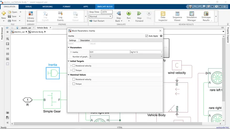
The block has one or two mechanical rotational conserving ports. The difference is purely graphical, as the ports are rigidly linked. The block positive direction is from its port to the reference point. This means that the inertia torque is positive if the inertia is accelerated in the positive direction.
An inertia block has been added to the workspace to provide an ideal mechanical rotational inertia for the simple gear block. This block has only one mechanical rotational conserving port and the positive direction of the block is from the port to the reference point which would be the simple gear in this case. The inertia torque acts in the positive direction is the inertia is accelerated in the positive direction. The inertia block is shown below:
Wind velocity and Road incline
- Add two PS constant block and connect them to the wind(W) and Road Inclination (beta) ports of the vehicle body Block
- measure the vehicle speed using the V Port of the vehicel Body Block.
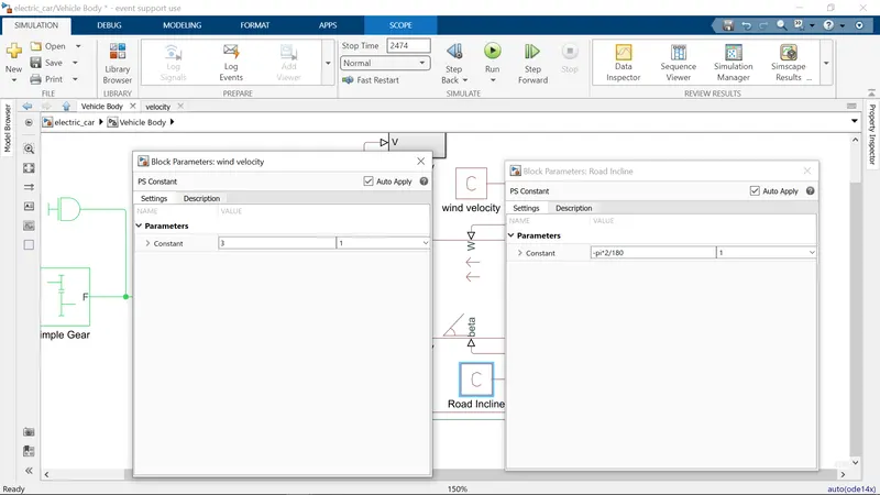
For calculating the velocity here, we have created a subsystem i.e LOG mph, this block basically consists of PS Simulink converter, Gain, Zero order Hold.
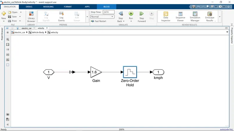
- Gain Block: 1.61 and it multiply input value with constant input.
- Zero-order Hold: 0.01, The Zero-Order Hold block holds its input for the sample period you specify.
Motor
This block represents the electrical and torque characteristics of a DC motor.
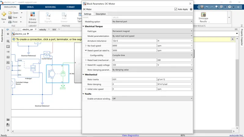
here the motor is set as 60kw and 330v DC supply 6000RPM with no load with laod 5000RPM
The block assumes that no electromagnetic energy is lost, and hence the back-emf and torque constants have the same numerical value when in SI units. Motor parameters can either be specified directly, or derived from no-load speed and stall torque. If no information is available on armature inductance, this parameter can be set to some small non-zero value.
When a positive current flows from the electrical + to - ports, a positive torque acts from the mechanical C to R ports. Motor torque direction can be changed by altering the sign of the back-emf or torque constants.
For the EV model, I have selected to use a DC motor block as the motor. This is because DC motors are easier to model and have fewer parameters to modify for a particular application. For this model, a DC motor will do just fine. The DC motor block is shown above:
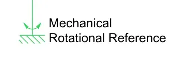
As we can see, there are 2 sides to the block: the mechanical side on the right and the electrical side on the left. The mechanical side has 2 ports, C and R. The C refers to the casing and the R for the rotation of the rotor which produces a torque. The electrical side has a positive and a negative terminal for the voltages to be applied. If a positive voltage is applied to the DC motor block from the positive to the negative terminal, a positive torque will act from the C port to the R port. The direction of the torque produced by the DC motor can be changed by changing the sign of the back emf or the torque constant. The C port of the mechanical side needs to be connected to a mechanical rotational reference because it will be stationary. The R port will be connected to the open connection of the simple gear from the vehicle body block. The positive terminal on the electrical side is connected to the positive terminal of a power converter which in my case will be an 'H bridge'.
The mechanical rotational reference block is shown below:
Power Converter
H-bridge
This block represents an H-bridge motor drive. The block can be driven by the Controlled PWM Voltage block in PWM or Averaged mode. In PWM mode, the motor is powered if the PWM port voltage is above the Enable threshold voltage. In Averaged mode, the PWM port voltage divided by the PWM signal amplitude parameter defines the ratio of the on-time to the PWM period. Using this ratio and assumptions about the load, the block applies an average voltage to the load that achieves the correct average load current. The Simulation mode parameter value must be the same for the Controlled PWM Voltage and H-Bridge blocks.
If the REV port voltage is greater than the Reverse threshold voltage, then the output voltage polarity is reversed. If the BRK port voltage is greater than the Braking threshold voltage, then the output terminals are short circuited via one bridge arm in series with the parallel combination of a second bridge arm and a freewheeling diode. Voltages at ports PWM, REV and BRK are defined relative to the REF port.
If exposing the power supply connections, the block only supports PWM mode.
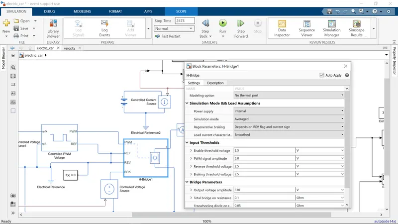
The power converter is needed to provide power of the correct form and magnitude from one component to another. In the case of EVs, a power converter is needed to provide a DC voltage from the battery of the EV to the DC motor so that it can operate properly with the required parameters. As mentioned earlier, I have used an H-Bridge motor drive as my power converter. Its block is shown above:
The H Bridge has 2 sides to it: the left side is for the controlling of the voltage signals and the right side is for the terminals to provide the controlled voltage to the DC motor. The left side ports of the H-Bridge block are:
- PWM - This stands for Pulse Width Modulation which will provide the voltage pulses to the H-Bridge either in the PWM or average mode.
- REF - This stands for Reference.
- REV - This stands for Reverse.
- BRK - This stands for Brake.
Controlled PWM Voltage
This block creates a Pulse-Width Modulated (PWM) voltage across the PWM and REF ports. The output voltage is zero when the pulse is low, and is equal to the Output voltage amplitude parameter when high. Duty cycle is set by the input value.
At time zero, the pulse is initialized as high unless the duty cycle is set to zero or the Pulse delay time is greater than zero.
The Simulation mode can be set to PWM or Averaged. In PWM mode, the output is a PWM signal. In Averaged mode, the output is constant with value equal to the averaged PWM signal.
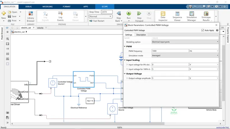
Next, I have used a 'Controlled PWM Voltage' block to provide a controlled pulse width modulated voltage to the H-Bridge block. The block will output the PWM voltage through its 'PWM' and 'REF' ports which will feed in to the same ports found on the H-Bridge block. If the pulse is low the output voltage is considered 0V whereas if the pulse is high, the output voltage will be equal to the output voltage amplitude which was set to 330V in the H-Bridge block. The pulses of voltage created by this block are dependent on the duty cycle which is the ratio of the time that the switch is ON to the time taken for 1 cycle (which is the time for which the switch is ON and OFF). The duty cycle is set by the input of the controlled PWM voltage block.
Controlled Voltage Source
The input ports of the controlled PWM voltage block are still unconnected and that is because they require a controlled voltage source to provide the voltages to produce the voltage pulses to be fed in to the H-Bridge. For this, I have used the controlled voltage source block. This block is useful because it will provide the necessary voltage that is powerful enough to maintain the voltage at the output regardless of the current that passes through it. This controlled voltage source block is shown below:
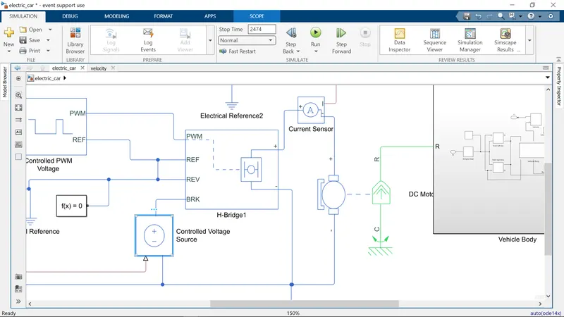
The block represents an ideal voltage source that is powerful enough to maintain the specified voltage at its output regardless of the current passing through it. The output voltage is V = Vs, where Vs is the numerical value presented at the physical signal port.
In this model, 2 controlled voltage sources have been used. One block is to provide the voltage for the acceleration of the vehicle and the other is to provide the voltage for the deceleration of the vehicle.
Electrical Reference
The electrical reference block is used to create a grounding effect for electrical circuits. Any model that uses electrical or electronics components will need to have at least one electrical reference block in it. The electrical reference block is shown below:
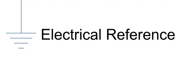
In my EV model, we are using this block for 2 occasions. The first is for to create an electrical ground between the controlled voltage source, controlled PWM voltage and the H-Bridge blocks. The second is for the battery system which will be modelled afterwards.
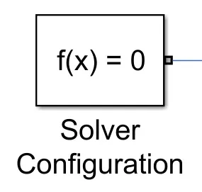
Solver Configuration
The solver configuration block is used to solve any necessary equations in a model and in my case, I have used them in the connection to the 'REV' port of the H-Bridge block. The solver configuration block is shown below:
Longitudinal Driver
The longitudinal driver block is used for giving normalized acceleration and deceleration commands to a controller based on 2 sets of data. The first data set is the reference velocity and the second data set is the feedback velocity. The longitudinal driver block is shown below:
A parametric longitudinal speed tracking controller for generating normalized acceleration and braking commands based on reference and feedback velocities.
Use the external actions to input signals that can disable, hold, or override the closed-loop commands determined by the block. The block uses this priority for the input commands: disable, hold, override.
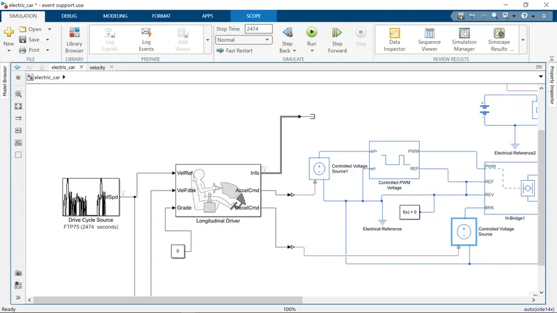
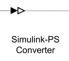
The working of the longitudinal driver block is simple. The reference velocity data coming from a drive cycle source is compared to the feedback velocity data coming from the vehicle body block. If the reference velocity is greater than the feedback velocity, an acceleration command will be given as an output to the controlled voltage source. If the reference velocity is lesser than the feedback velocity, a deceleration command is given as the output to another controlled voltage source instead. For the acceleration and deceleration commands to be given as output signals, I have used a Simulink - PS converter block. This block is needed whenever we wish to connect a Simulink input signal to a physical signal. In this case, the input signal is velocity data and this is logic data which we want to convert to a physical signal i.e.. voltages to the controlled voltage source.
The Simulink - PS converter block is shown below:
Drive Cycle
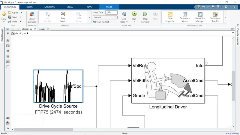
A drive cycle is a data set that contains velocity and time data for the purpose of modelling the motion of a vehicle. The drive cycle will be a plot of the velocity against the time and it is made to resemble typical driving conditions that a consumer may experience themselves in. For instance, they can model highway driving situations, driving in urban areas, or driving with full power etc. Drive cycles are used by automotive companies for various testing procedures such as mileage, pollution tests, and acceleration and top speed tests. There are various different drive cycles that are industry standard e.g. Urban Dynamometer Driving Schedule (UDDS), FTP 75.
By default, the drive cycle block is set to the FTP75 drive cycle. This can be modified by opening the block parameters shown below
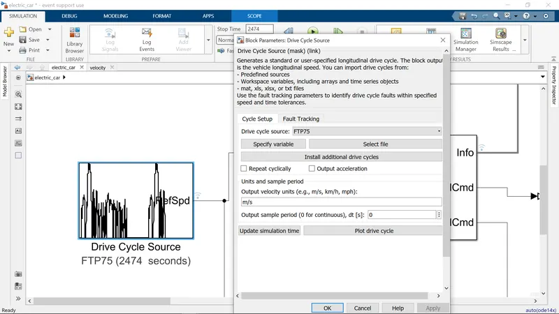
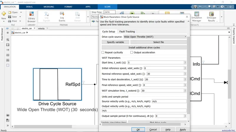
In my EV model, a drive cycle is used as the reference velocity data for the longitudinal driver block to send acceleration or deceleration commands according to the drive cycle. There are 3 ways of implementing a drive cycle. One method is to create or own drive cycle with a spreadsheet of velocity data in one column and time data in another column. Another method is to use a signal builder block and create signals that represent the velocities at which the vehicle should travel and the durations for which those velocities are to be maintained. The last method is to use the industry standard drive cycles which are in - built in to the SIMULINK library. In my case, I have used an industry standard 'WOT' drive cycle. This drive cycle stands for 'Wide Open Throttle' and it models the situation where the vehicle is made to accelerate at full power and maintained at a particular speed and made to decelerate back to rest.
When the 'WOT' drive cycle is chosen, some extra parameters are made available for modification which are shown below:
Battery System
Battery
This block models a battery. If you select Infinite for the Battery charge capacity parameter, the block models the battery as a series internal resistance and a constant voltage source. If you select Finite for the Battery charge capacity parameter, the block models the battery as a series internal resistance plus a charge-dependent voltage source defined by:
V = Vnom*SOC/(1-beta*(1-SOC))
where SOC is the state of charge and Vnom is the nominal voltage. Coefficient beta is calculated to satisfy a user-defined data point [AH1,V1].
The battery will be the energy store of the EV and will contain the electrical energy in DC form and provide this energy to the DC motor for it to operate. The battery block used is a simple one and considers only the basic parameters. The battery block and parameters are shown below:
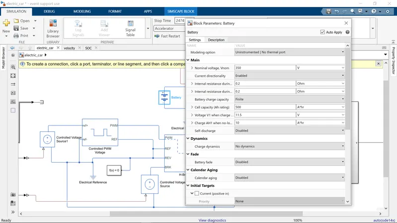
As we can see, the battery block parameters include the nominal voltage, the internal resistance and the battery charge capacity. I have used a nominal voltage of 350v, an internal resistance of 0.2 Ohms and an infinite battery charge capacity. The nominal voltage is selected so that it is more than sufficient to supply the voltage to the DC motor and the H-Bridge blocks.
500ah battery capacity for draive cycle
Controlled Current Source
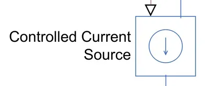
The controlled current source block is a part of the battery system used in the EV model. Similar to the controlled voltage source, this block will represent an ideal current source that is powerful enough to maintain the specified current regardless of the voltage across it. The controlled current source block is shown below:
Current Sensor
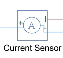
The current sensor block represents an ideal current sensor and is used to convert the current measured in an electrical circuit to a physical signal that is proportional to the current. This block is used to measure the current between the battery circuit (controlled current source) and the DC motor. The current sensor block is shown below:
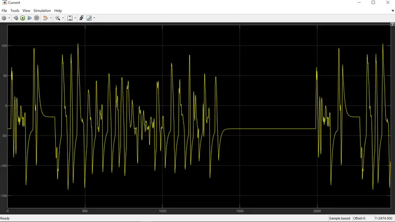
SOC & Current
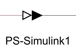
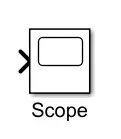
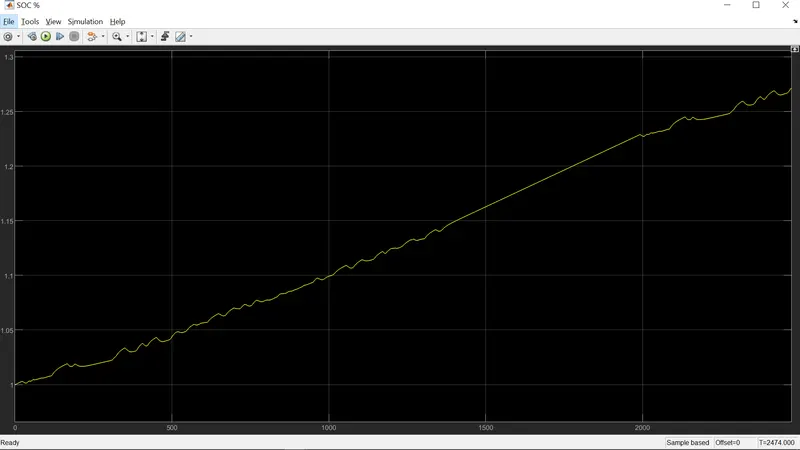
SOC stands for state of charge and it is a measurement of the available charge in a battery. When a battery is fully charged, it is considered to have a 100% charge and conversely 0% charge if fully discharged. In this EV model, I want to measure the current and the SOC of the battery as the simulation is run. For this, I have used a scope block which shows the output signal we wish to measure as a plot against time. 2 scopes have been used, one for the current and the other for the SOC. In order for this to be measured, we need to use a 'PS - Simulink converter' block. This is because the current signal is a physical one and we are measuring it as a logic signal in the SIMULINK workspace.
The PS-Simulink converter block is shown below:
The scope block is shown below:
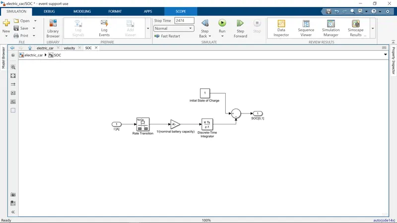
SOC Subsystem
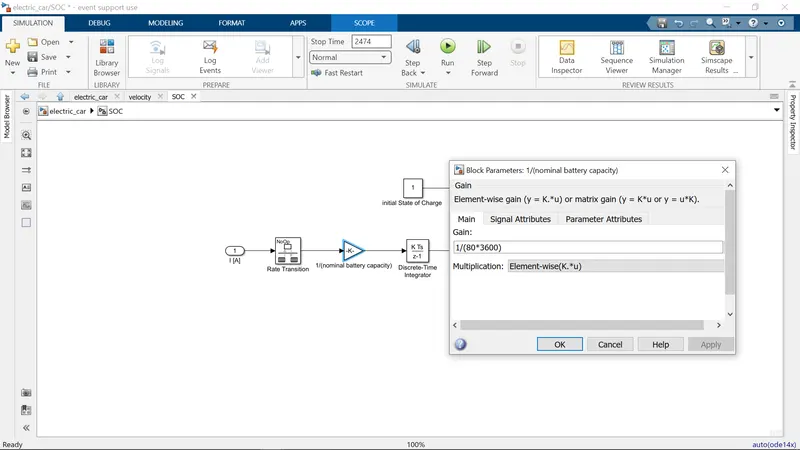
To measure the state of charge of the battery, a subsystem was created of various blocks. The first block is the 'Rate Transition' block and it is used to handle data transfer between different rates and tasks. Next, a 'Gain' block is used in order to multiply or divide the signal coming from the rate transition block. In this case, the gain block will divide the current signal with the ampere rating of the battery which has been taken as 80Ah multiplied by 3600 (seconds in an hour). This is shown in the gain block parameters below:
Speed Measurement
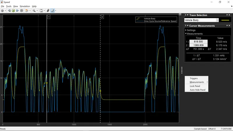
In order to measure the speed of the EV model, I needed to use the scope block once again. I modified the scope block to have 2 input ports where one port takes the output velocity signal from the vehicle subsystem block and the other port takes the output signal from the drive cycle to the reference velocity port on the longitudinal driver block. This has been done so that the scope can show us the plots of the reference velocity and the actual velocity of the vehicle to see how they compare with each other.
Distance Measurement
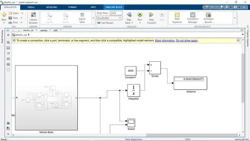
I have used the scope block and mathematical operator blocks to measure the distance travelled by the vehicle according to the drive cycle data. The area under a velocity time graph tells us the distance travelled by an object and so in my model. This means that the integral of the velocity with respect to time, gives us the distance travelled. So, I have implemented the integrator block to integrate the velocity signal that is output from the vehicle subsystem.
The integrator block is shown below:
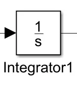
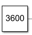
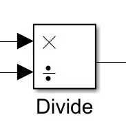
From the integrator block, I needed to use the 'Divide' block along with a 'Constant' block having a value of 3600 in order to convert the divide the integrated speed signal which is in kilometres per hour by 3600. This will give us the distance travelled in kilometres.
The constant block with a value of 3600:
The 'Divide' block:
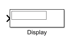
Finally, a 'Display' block is used to show the distance travelled as the simulation is run. The display block is shown below:
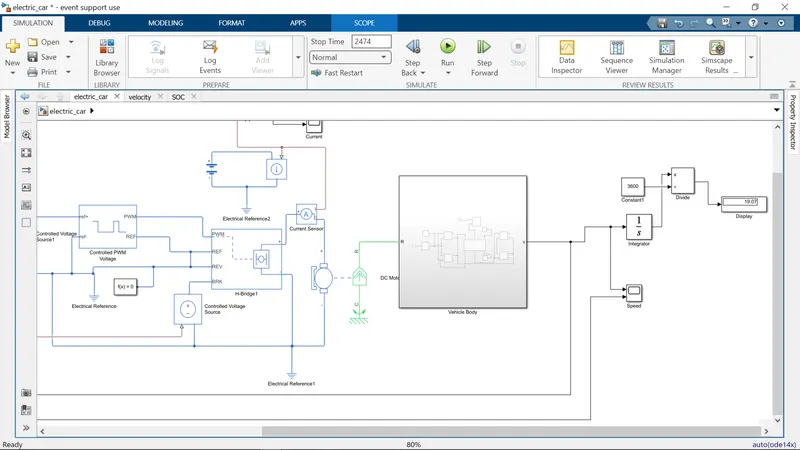
result respose
Current
SOC%
distance here shown in display.
Conclusion:
The total distance travel by vehicle is 6.05 kmph depending upon the FTP75 drive cycle and the total time for simulation was 2474 sec.
The battery is having 350v which is a nominal voltage and the battery ampere per hour rating is 50 by which we calculated the SOC (state of charge) of battery.
The DC motor is used to run the Rear axel of the vehicle and when the car is with no load condition then the motor operating RPM is 5000 and when the car is running at some load or we can say that some rated speed then the motor RPM is taken as 6000. The voltage supply to DC motor is 330v.