Project - Speed Control of a Direct Current (DC) motor
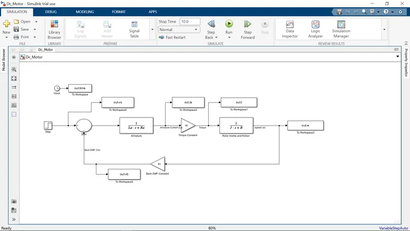
Aim: To design a Simulink model for the DC motor shown in Figure 1. amd aslo by Using the Proportional, Integral, and Derivative (PID) control design knowledge gained in the training to design, develop and test a controller to maintain a desired speed for the motor.
The Project is based on speed control of a DC Motor By Using PID Controller.
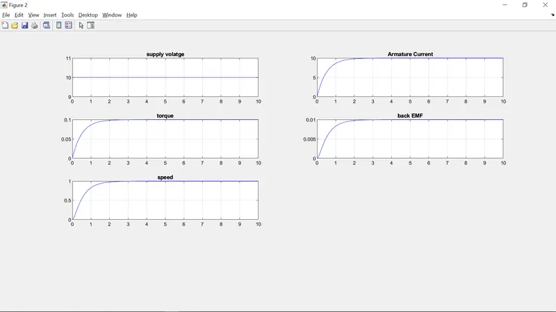
Initially,simulink model of a Dc Motor is constructed, then make it as subsystem called "DC MOTOR".
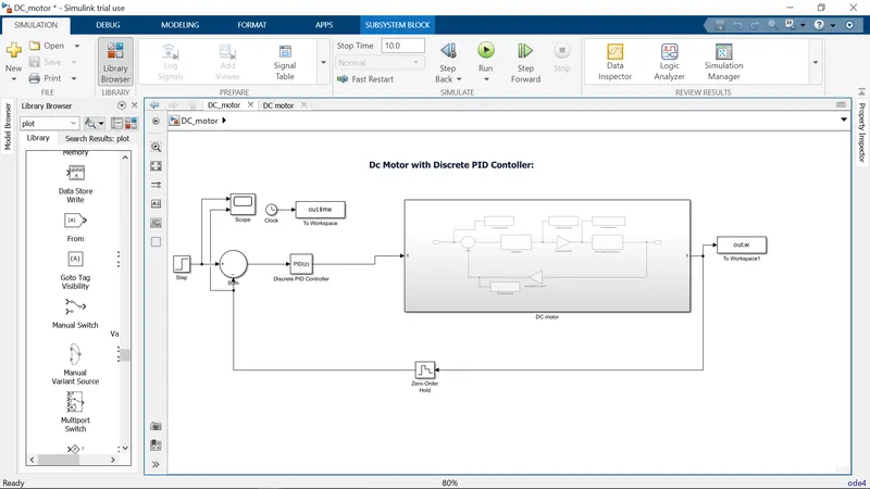
Design Dc Motor with Discrete PID Contoller:
Here, we make Dc motor as Subsystem and pid Controller is Used to Control Desired Speed.
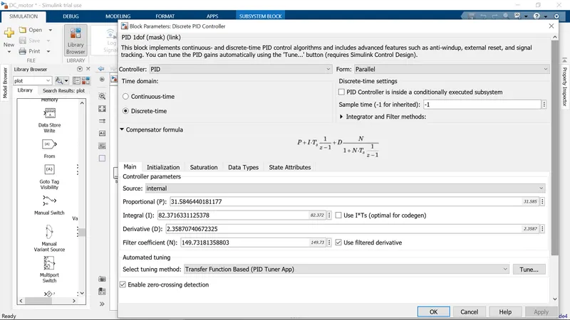
Block Parameters Of Discrete PID Controller:
Initially Kp=1,Ki=1,Kd=0, After Tuning we set Kp,Ki,Kd as 31.58, 82.37, 2.35 Respectively. To Obtain Desing Control Objectives Of settling time ,overshoot and Steady State Error within the limit.
Scope Results:
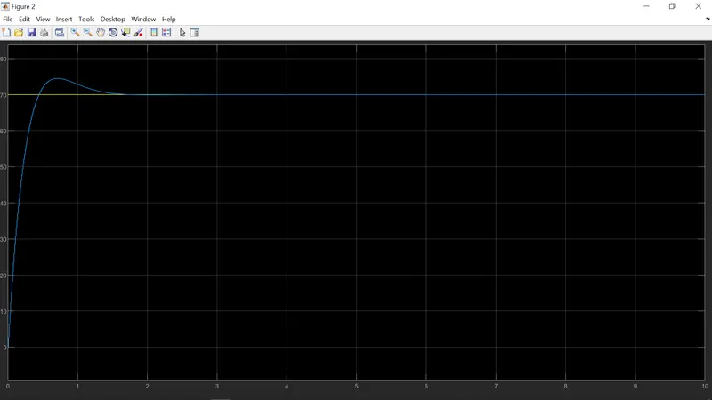
1) To maintain a desired speed for the motor (case 1:Desired Speed = 70):
2) To maintain a desired speed for the motor (case 2:Desired Speed = 230):
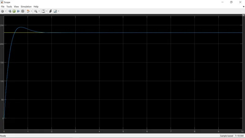
In above two cases,we change desired speed as 70 in case 1 and 230 in case 2 , since the both a case, Plotting Remains same. Hence, we maintain desired Speed For a Dc Motor.