Project-1: Modelling an electric Car with Li-ion battery
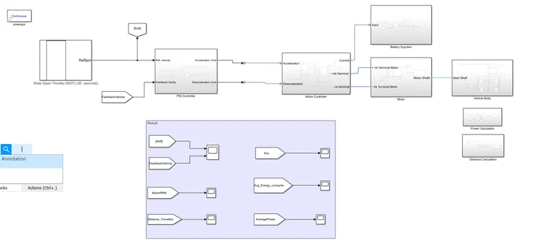
Aim :- Create a MATLAB model of electric car which uses lithium-ion battery and suitable motor. Choose suitable blocks from Simscape or Powertrain block set. Implement the vehicle speed control using PI controller and generate brake and accelerator commands. Avoid using readymade driver block for speed control.
System Confirgaration :-
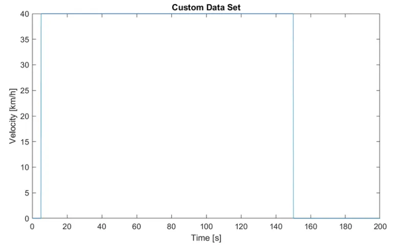
Drive Cycle :-
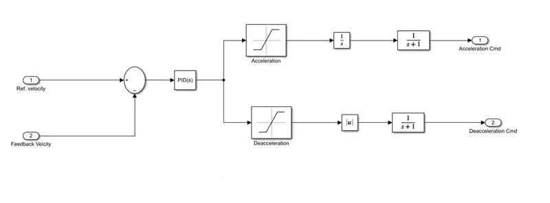
PID controller subsystem:-
SUM Block :-
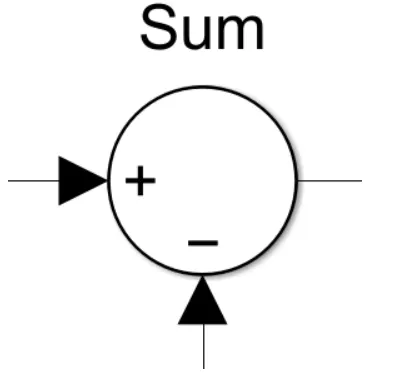
This block subtracts feedback velocity from reference velocity.
This output is given to pid controller.
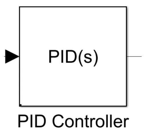
PID Controller:-
Parameter:-
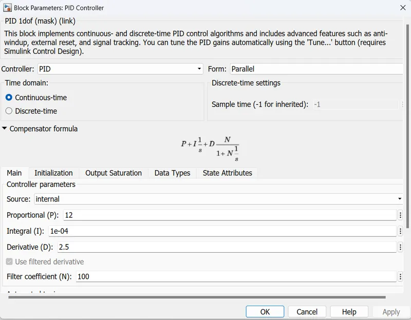
The output from the sum block is given to this block.
based on the PID, the output is generated.
Saturation Block:-
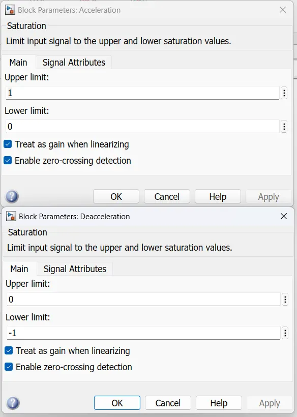
This block helps to limit the output signal from pid controller and separate deceleration and acceleration values.
The output from these blocks is sent to a transfer function then these are provided to motor controller block.
Motor Controller Subsystem:-
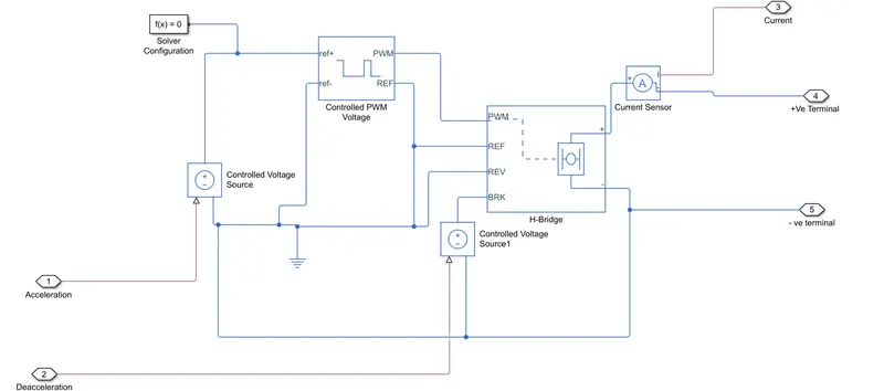
Controlled voltage source:-
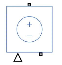
The Controlled Voltage Source block represents an ideal voltage source that is powerful enough to maintain the specified voltage at its output regardless of the current flowing through the source.
The output voltage is V = Vs, where Vs is the numerical value presented at the physical signal port.
Controlled PWM Voltage:-
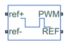
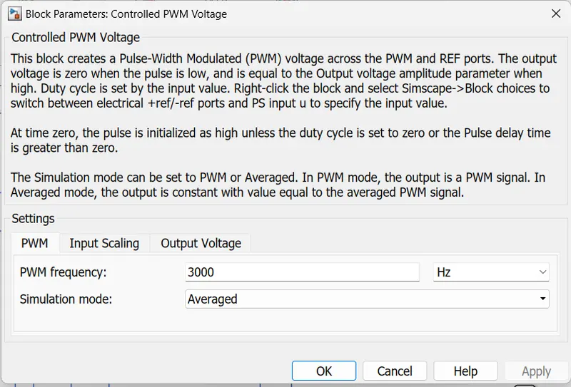
The Controlled PWM Voltage block represents a pulse-width modulated (PWM) voltage source. The block has two modeling variants,
Electrical input ports — The block calculates the duty cycle based on the reference voltage across its ref+ and ref- ports. This modeling variant is the default.
PS input — Specify the duty cycle value directly by using an input physical signal port.
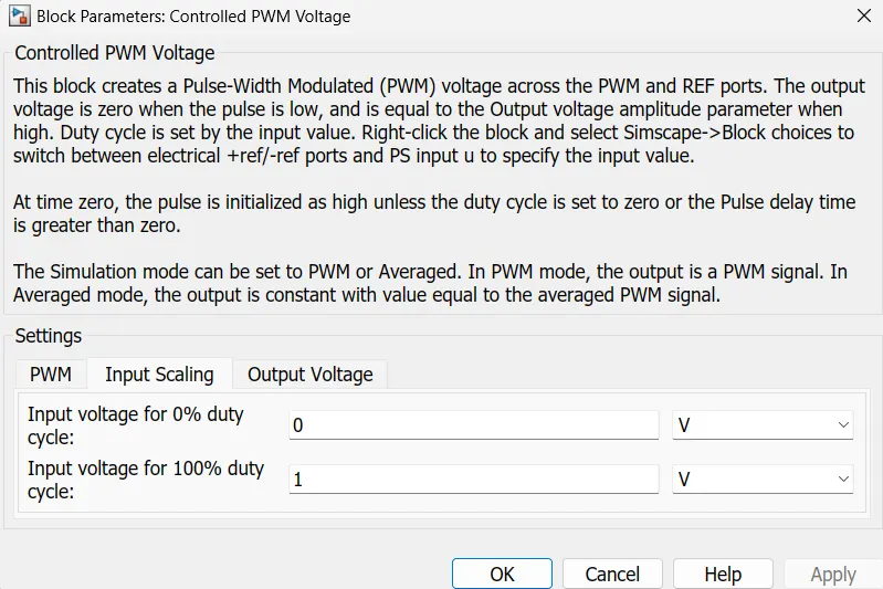
For the Electrical input ports variant of the block, the demanded duty cycle is
where:-
Vref is the reference voltage across the ref+ and ref- ports.
Vmin is the minimum reference voltage.
Vmax is the maximum reference voltage.
H-Bridge :-
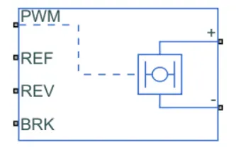
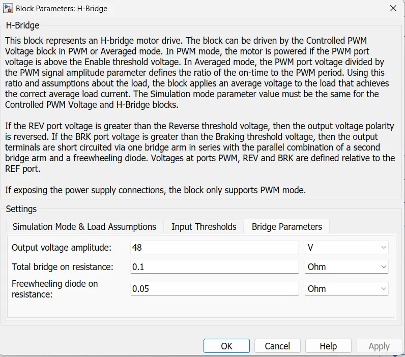
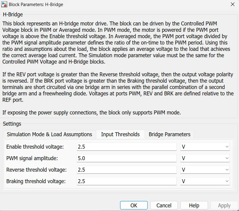
This block is used to change the polarity of the voltage applied across the DC motor so as to run the motor in forward and reverse direction as per the input command.
Current Sensor:-
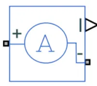
This block is used to measure the flow of current through a circuit
Motor Subsystem:-
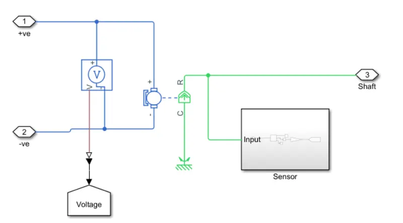
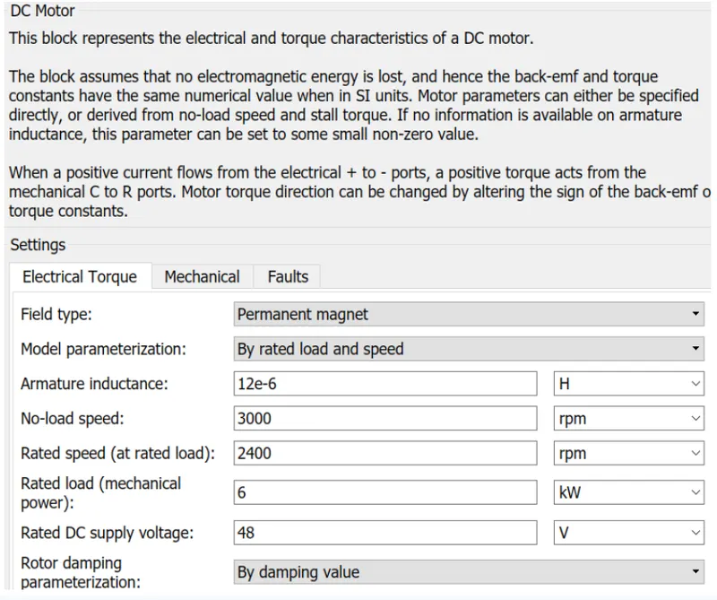
DC motor :-
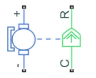
To convert the electrical energy to mechanical energy we use motors. In this electric vehicle model, we have used DC motor. This motor can act as a generator also in case of regenerative braking.
Sensor :-

The output from this block is in rad/sec. so, unit conversion is done in ps-simulink converter block.
Battery Subsystem :-
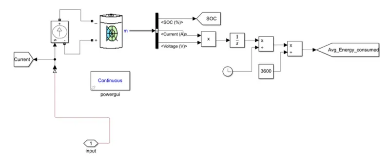
Controlled Current Source:
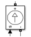
The Controlled Current Source block converts the Simulink input signal into an equivalent current source. The generated current is driven by the input signal of the block.
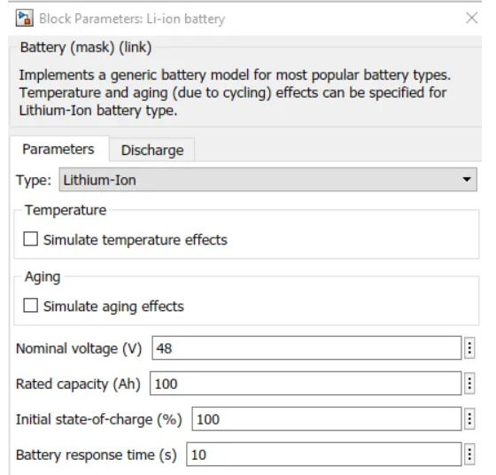
Li-ion battery:
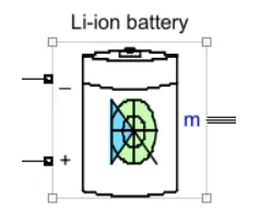
The Battery block implements a generic dynamic model that represents most popular types of rechargeable batteries.
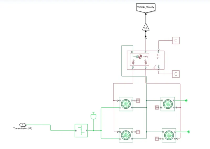
Vehicle Body Subsystem :-
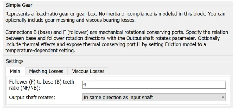
Fixed Gear : -
The Simple Gear block represents a gearbox that constrains the connected driveline axes of the base gear, B, and the follower gear, F, to corotate with a fixed ratio that is specified.
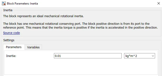
Inertia :-

The Inertia block represents an ideal mechanical rotational inertia
 Tire (Magic Formula) :-
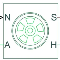
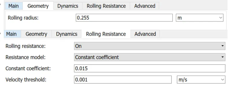
The Tire (Magic Formula) block models a tire with longitudinal behavior given by the Magic Formula an empirical equation based on four fitting coefficients. The block can model tire dynamics under constant or variable pavement conditions.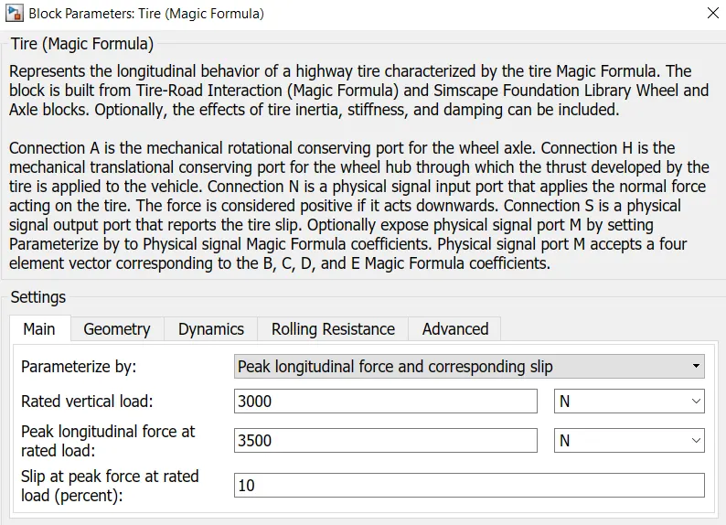
Vehicle Body :-
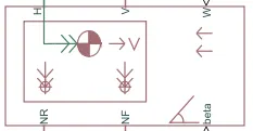
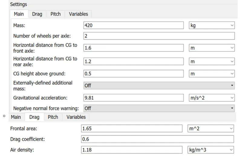
The Vehicle Body block represents a two-axle vehicle body in longitudinal motion. The vehicle can have the same or a different number of wheels on each axle. For example, two wheels on the front axle and one wheel on the rear axle. The vehicle wheels are assumed identical in size. The vehicle can also have a center of gravity (CG) that is at or below the plane of travel.
The block accounts for body mass, aerodynamic drag, road incline, and weight distribution between axles due to acceleration and road profile. Optionally include pitch and suspension dynamics. The vehicle does not move vertically relative to the ground.
The block has an option to include an externally-defined mass and an externally-defined inertia. The mass, inertia, and center of gravity of the vehicle body can vary over the course of simulation in response to system changes.
Result Plot :-
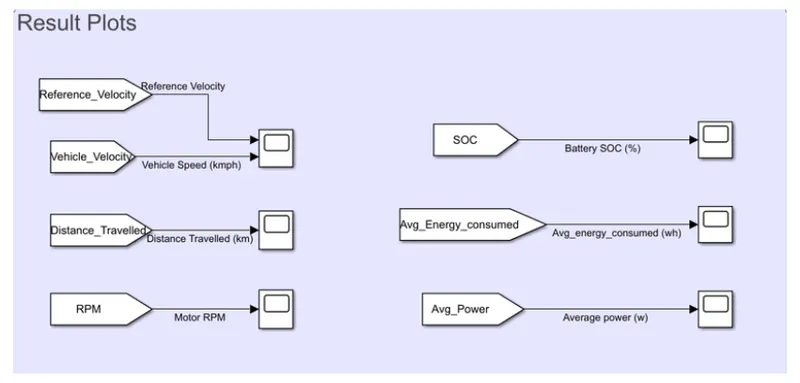
Results Plots : -
Reference Velocity vs Vehicle Velocity : -
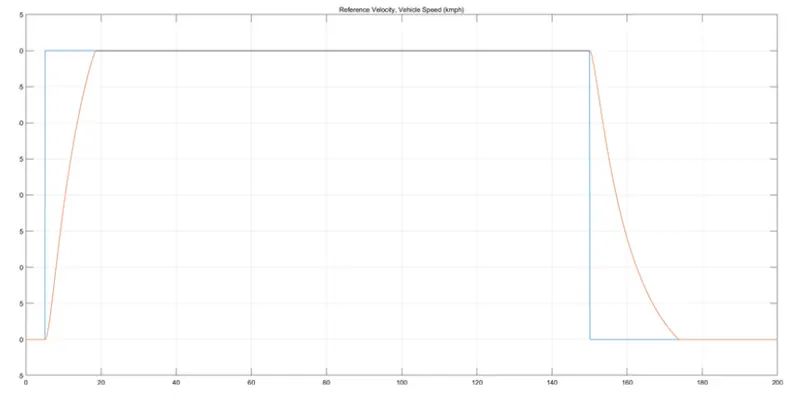
As per above plot, we can see 0 - 40kmph is achieved in 14sec.
Distance Travelled (km) :-
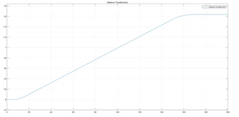
Distance Travelled is 1.64km
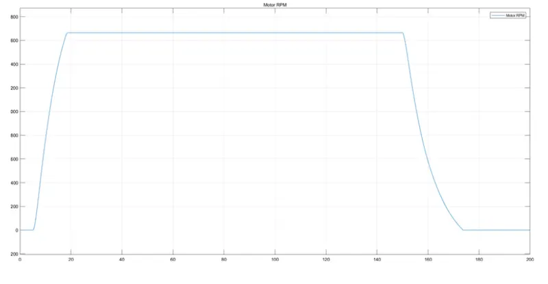
Motor RPM :-
SOC (%) :-
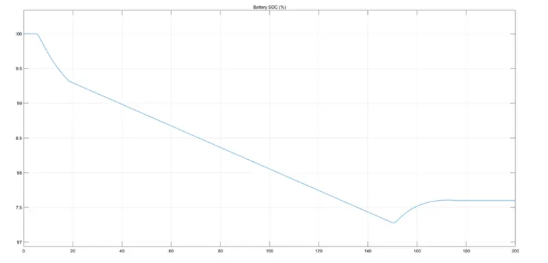
Battery SOC dropped to 97.25%
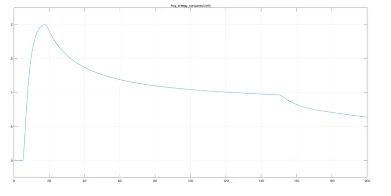
Average Energy Consumed (wH) :-
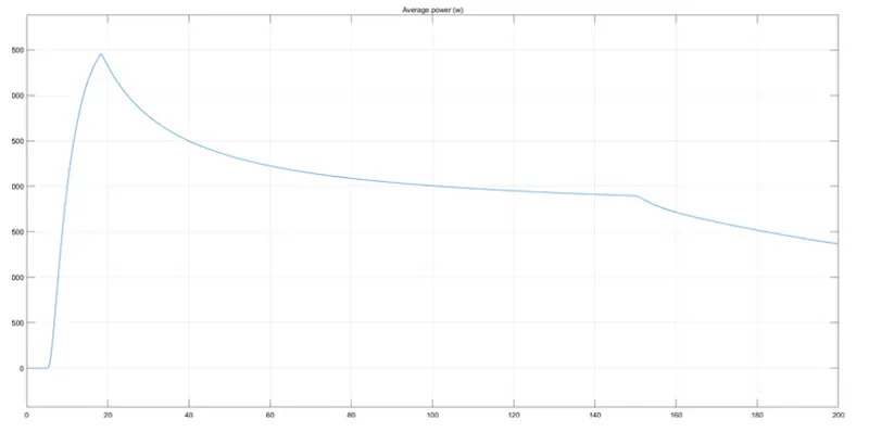
Average Power Consumed (kW) :-
Conclusion:
MATLAB model of electric car which uses lithium-ion battery and suitable motor is created.
****************************************************************************************************