Project 1 (Mini Project on Vehicle Direction Detection
Step-1
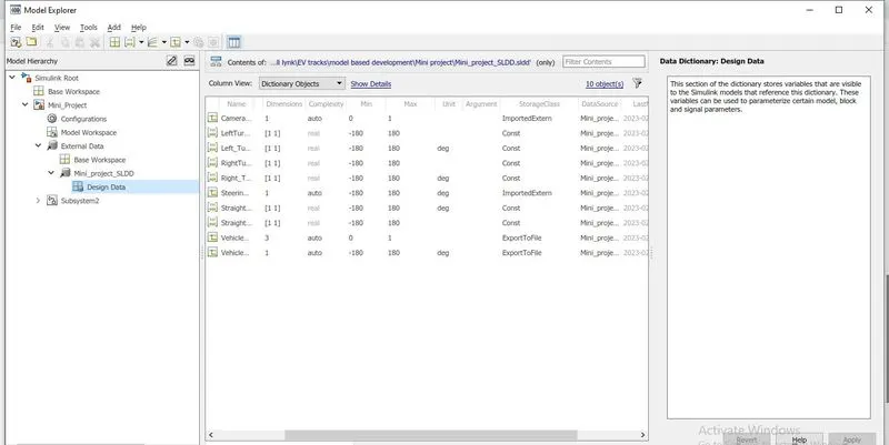
- To Create a sldd file to update all the given inputs, outputs & parameters on this file later calling these variables on the Simulink blocks are shown in the fig.
Step-2 Resolve and propagation:
- In this case, we have updated our signals inputs in the sldd file so we have to add the signal into the connection lines to get the proper output.
- So, we have used the resolve and propagation method on this model
Steps to get resolve and propagate signals.
- once right-click the line a popup window can be opened select properties option to open the resolve and propagate option.
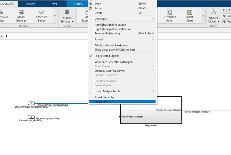
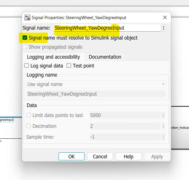
- In that window, we may type the required input signals which is updated in the ssld file and select the resolve option to resolve the signal.
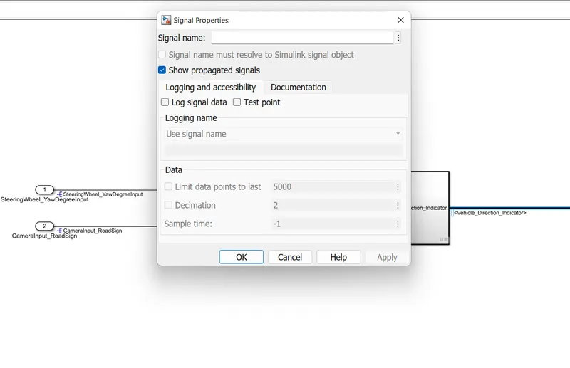
- In that window, we may type the required input signals which is updated in the ssld file and select the propagate option to propagate the signal.
Step-3
Model explanation:
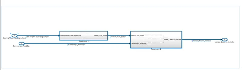
- First I can create two sub-systems and name as requirement-1 & requirement-2
Requirement-1 subsystem:
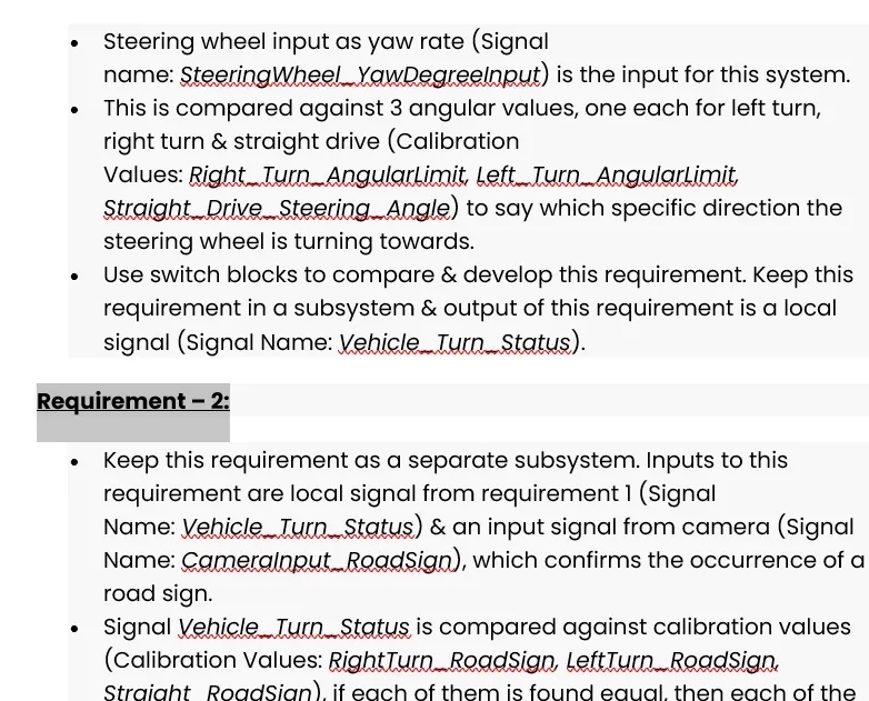
- Steering wheel input as yaw rate (Signal name: SteeringWheel_YawDegreeInput) is the input for this system.
- This is compared against 3 angular values, one each for left turn, right turn & straight drive (Calibration Values: Right_Turn_AngularLimit, Left_Turn_AngularLimit, Straight_Drive_Steering_Angle) to say which specific direction the steering wheel is turning towards.
- Use switch blocks to compare & develop this requirement. Keep this requirement in a subsystem & the output of this requirement is a local signal (Signal Name: Vehicle_Turn_Status).
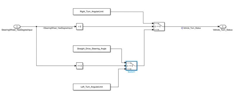
- As per the requirements, 1 can design this model, when the steering yaw degree is considered as input is connected to the relational operator and the relational operator is connected with the switch based on the if-else condition the switch is given the output as a boolean number.
- For eg if I'm given -120 deg as input means when the relation operator checks the given input once it fails means its automatically switch the false statement when the false statement is connected to the left-turn_drive so the the switch given the output the left-turn value.
Requirment:2 Subsystem:
- Keep this requirement as a separate subsystem. Inputs to this requirement are a local signal from requirement 1 (Signal Name: Vehicle_Turn_Status) & an input signal from the camera (Signal Name: CameraInput_RoadSign), which confirms the occurrence of a road sign.
- Signal Vehicle_Turn_Status is compared against calibration values (Calibration Values: RightTurn_RoadSign, LeftTurn_RoadSign, Straight_RoadSign), if each of them is found equal, then each of the three corresponding outputs is compared against the camera input signal,
- Using a logical operator block, only one among them is finally given as the output signal (Signal Name: Vehicle_Direction_Indicator).
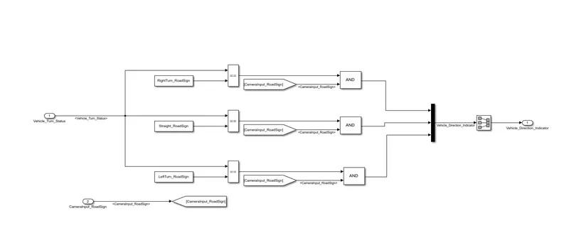
- As per requirement statement-2 i have to compare the vehicle turn status and the camera sign once is true means the vehicle can conclude the turn is based on the road sign.
- So, i have to taken the vehicle turn status as input and it would be given to the relational operator which is the road sign is compared with the vehicle turn status.
- and i use the and gate which is used to given the any one output to the mux at a time for if left turn status is true means right turn and straight turn will be fale so that's why I'm using the And gate in this subsytem.
- The basic objective of the subsystem is to comape the vehicle turn status with the road sign.
Step-4 Generating codes without SIL testing process:
- After completion of the model we have generate the required code without Done the SIL test.
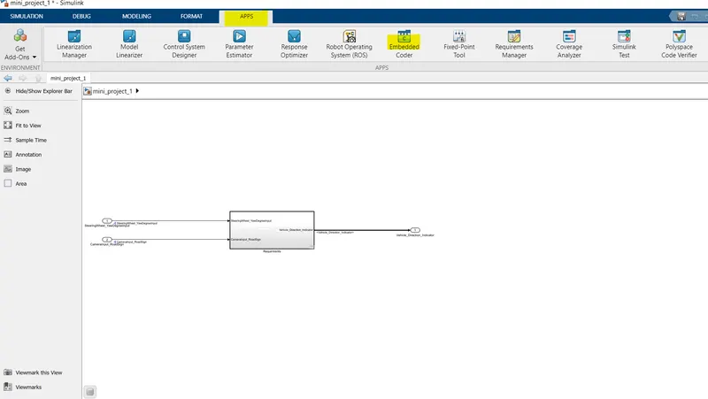
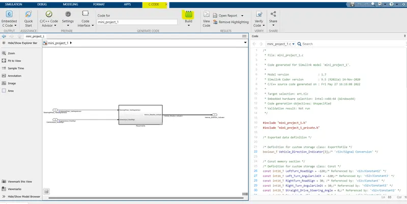
- Select the apps option which is available on the top the Simulink window then select the embedded code option to generate the code are shown below.
=======================================================================================
/*
* File: Mini_Project.c
*
* Code generated for Simulink model 'Mini_Project'.
*
* Model version : 1.18
* Simulink Coder version : 9.3 (R2020a) 18-Nov-2019
* C/C++ source code generated on : Sun Feb 12 16:11:20 2023
*
* Target selection: ert.tlc
* Embedded hardware selection: Intel->x86-64 (Windows64)
* Code generation objectives: Unspecified
* Validation result: Not run
*/
#include "Mini_Project.h"
#include "Mini_Project_private.h"
/* Exported data definition */
/* Definition for custom storage class: ExportToFile */
/* Const memory section */
/* Definition for custom storage class: Const */
/* Referenced by: '/LeftTurn_RoadSign' */
/* Referenced by: '/Left_Turn_AngularLimit' */
/* Referenced by: '/RightTurn_RoadSign' */
/* Referenced by: '/Right_Turn_AngularLimit' */
/* Referenced by: '/Straight_Drive_Steering_Angle' */
/* Referenced by: '/Straight_RoadSign' */
/* Real-time model */
/* Model step function */
{
/* Switch: '/Switch' incorporates:
* Constant: '/Left_Turn_AngularLimit'
* Constant: '/Right_Turn_AngularLimit'
* Constant: '/Constant'
* Constant: '/Constant'
* Inport: '/steeringwheel_yawdegreeinput'
* RelationalOperator: '/Compare'
* RelationalOperator: '/Compare'
* Switch: '/Switch1'
*/
/* Switch: '/Switch1' incorporates:
* Constant: '/Straight_Drive_Steering_Angle'
*/
} else {
}
/* End of Switch: '/Switch' */
/* SignalConversion: '/Signal Conversion' incorporates:
* Constant: '/LeftTurn_RoadSign'
* Constant: '/RightTurn_RoadSign'
* Constant: '/Straight_RoadSign'
* Inport: '/CameraInput_RoadSign'
* Logic: '/AND'
* Logic: '/AND1'
* Logic: '/AND2'
* RelationalOperator: '/Relational Operator'
* RelationalOperator: '/Relational Operator1'
* RelationalOperator: '/Relational Operator2'
*/
}
/* Model initialize function */
{
/* (no initialization code required) */
}
/* Model terminate function */
{
/* (no terminate code required) */
}
/*
* File trailer for generated code.
*
* [EOF]
*/
=======================================================================================
- After completion of this process, code is generated gradually can shown the above fig.
step 5- Requirement tagging
- in this project, I can update my project details and block explanation in ms word which attach with this model hereafter anyone is able to know the definition and requirements of the block means just simply click the requirement option to Simulink and automatically open the ms word file and highlight the paragraph or points.
- Make sure while doing this requirement process your ms word application should be open.
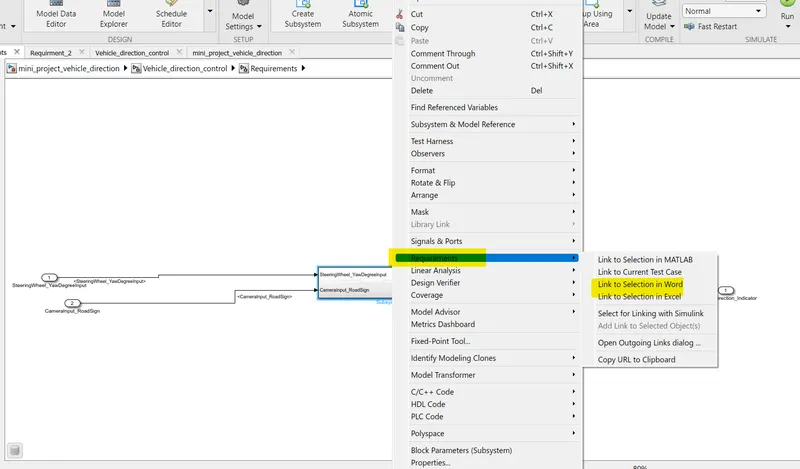
- Once we right-click the subsystem then select the requirements option and select the link to the word or excel with our comfortable are shown above the fig.
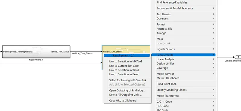
- After linking the requirements with the word we have to check the requirements.
Requirement-1:-