Project 1 (Mini Project on Vehicle Direction Detection
Your Answers
Advanced Driver Assistance Systems
Mini Project - Vehicle Direction Determination
General Overview:
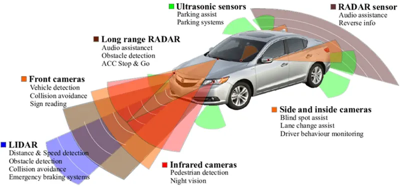
Identifying the direction of the vehicle is one of the important & diverse features in Autonomous driving & Advanced Driver Assistance Features. This particular sub-feature of identifying the direction of the vehicle is basically identifying the direction the vehicle is taking based on the camera input.
The camera reads the road signs & stores them into its memory with unique values for the left turn, right turn & straight drive. Depending on the direction it is taking, the final indication is given to the driver – as an indication if he is driving in the recommended direction or not.
Vehicle Direction Determination can also be coupled alongside features like GPS systems to identify whether the vehicle is reaching its destination in an optimized manner. This sub-feature can also be used along with Lane Detection, Highway Warning, Ramp Entry / Exit in Wrong Way Detection etc.
The objective of the Mini Project:
- Development of MATLAB Simulink model as per requirement.
- Tag the requirements to the Simulink model; tagging requirement 1 & requirement 2 to their corresponding subsystems is fine.
- MBD compliant changes, Data Dictionary creation & code generation is added advantage, and that is not the scope of this project.
- If choosing code generation, Storage class for Input signals: ImportedExtern; Storage class for Output signal: Export to File; Storage class for local signals: localizable; Storage class for calibration signals: Const.
- Choose sample time for all signals as 0.01s
Requirement - 1:
- Steering wheel input as yaw rate (Signal name: SteeringWheel_YawDegreeInput) is the input for this system.
- This is compared against 3 angular values, one each for the left turn, right turn & straight drive (Calibration Values: Right_Turn_AngularLimit, Left_Turn_AngularLimit, Straight_Drive_Steering_Angle) to say which specific direction the steering wheel is turning towards.
- Use switch blocks to compare & develop this requirement. Keep this requirement in a subsystem & the output of this requirement is a local signal (Signal Name: Vehicle_Turn_Status).
Requirement – 2:
- Keep this requirement as a separate subsystem. Inputs to this requirement are a local signal from requirement 1 (Signal Name: Vehicle_Turn_Status) & an input signal from the camera (Signal Name: CameraInput_RoadSign), which confirms the occurrence of a road sign.
- Signal Vehicle_Turn_Status is compared against calibration values (Calibration Values: RightTurn_RoadSign, LeftTurn_RoadSign, Straight_RoadSign), if each of them is found equal, then each of the three corresponding output is compared against the camera input signal,
- Using a logical operator block, only one among them is finally given as output signal (Signal Name: Vehicle_Direction_Indicator).
Signals & Calibration Data List:
|
Signal / Calibration Name |
Signal Type |
Data Type |
Dimension |
Min |
Max |
Initial Value |
Units |
|
SteeringWheel_YawDegreeInput |
Input |
Int16 |
1 |
-180 |
180 |
- |
Deg |
|
CameraInput_RoadSign |
Input |
Boolean |
1 |
0 |
1 |
- |
- |
|
Vehicle_Turn_Status |
Local |
Int16 |
1 |
-180 |
180 |
- |
Deg |
|
Right_Turn_AngularLimit |
Calibration |
Int16 |
[1 1] |
-180 |
180 |
30 |
Deg |
|
Left_Turn_AngularLimit |
Calibration |
Int16 |
[1 1] |
-180 |
180 |
-120 |
Deg |
|
Straight_Drive_Steering_Angle |
Calibration |
Int16 |
[1 1] |
-180 |
180 |
0 |
Deg |
|
RightTurn_RoadSign |
Calibration |
Int16 |
[1 1] |
-180 |
180 |
30 |
|
|
LeftTurn_RoadSign |
Calibration |
Int16 |
[1 1] |
-180 |
180 |
-120 |
|
|
Straight_RoadSign |
Calibration |
Int16 |
[1 1] |
-180 |
180 |
0 |
|
|
Vehicle_Direction_Indicator |
Output |
Boolean |
1 |
0 |
1 |
- |
- |
- Designing the MATLAB MODEL
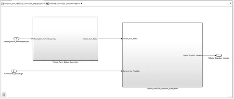
This the main model subsystem that having two inputs SteeringWheel_YawDegreeInput and CameraInput_RoadSign entering into the Vehicle Detection Determination subsystem and one output Vehicle_Direction_Indicator
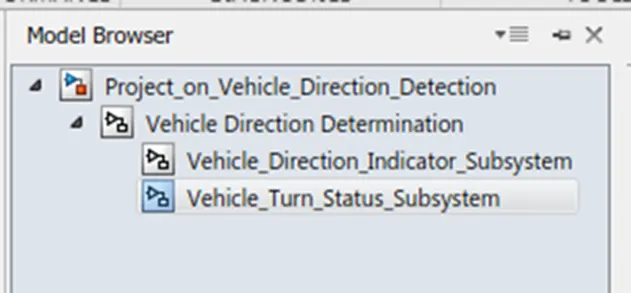
there are 2 requirements are designed in two subsystem
Requirement:- 1
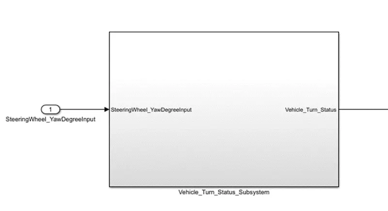
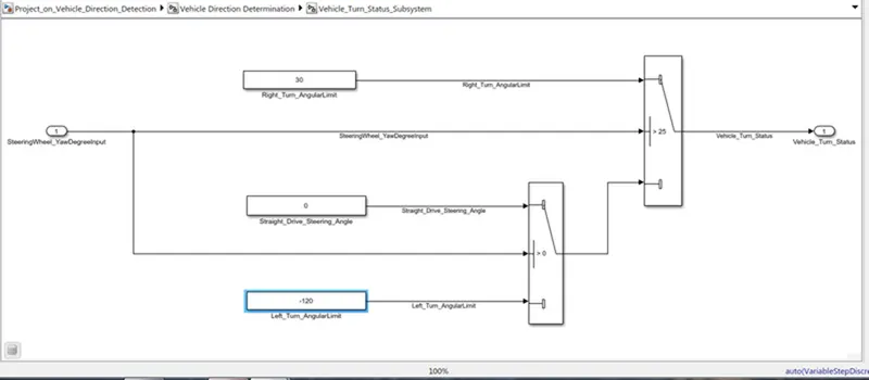
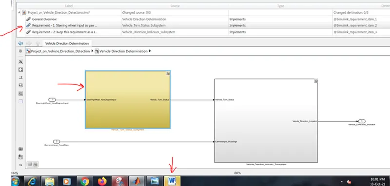
- Steering wheel input as yaw rate (Signal name: SteeringWheel_YawDegreeInput) is the input for this system.
- This is compared against 3 angular values, one each for a left turn, right turn & straight drive (Calibration Values: Right_Turn_AngularLimit, Left_Turn_AngularLimit, Straight_Drive_Steering_Angle) to say which specific direction the steering wheel is turning towards.
- Use switch blocks to compare & develop this requirement. Keep this requirement in a subsystem & the output of this requirement is a local signal (Signal Name: Vehicle_Turn_Status).
Requirement:- 2
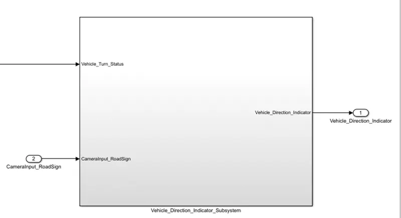
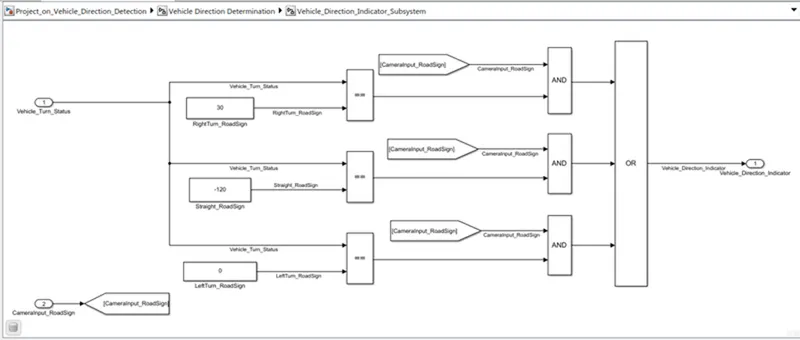
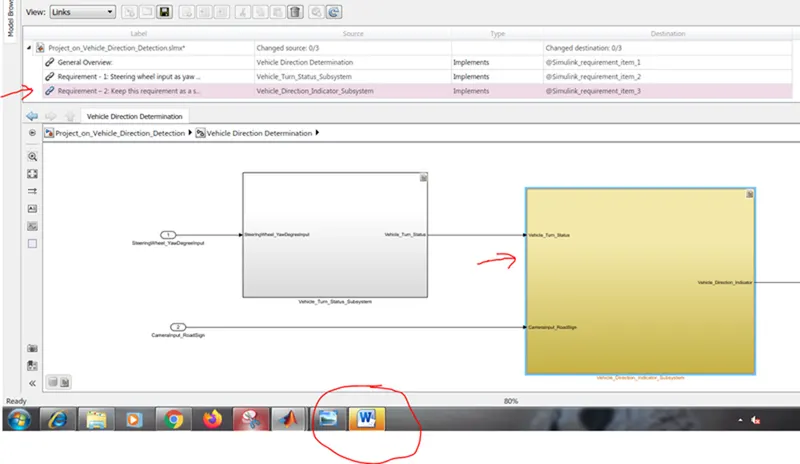
- Keep this requirement as a separate subsystem. Inputs to this requirement are a local signal from requirement 1 (Signal Name: Vehicle_Turn_Status) & an input signal from the camera (Signal Name: CameraInput_RoadSign), which confirms the occurrence of a road sign.
- Signal Vehicle_Turn_Status is compared against calibration values (Calibration Values: RightTurn_RoadSign, LeftTurn_RoadSign, Straight_RoadSign), if each of them is found equal, then each of the three corresponding output is compared against the camera input signal,
- Using a logical operator block, only one among them is finally given as output signal (Signal Name: Vehicle_Direction_Indicator).
- Requirement Tagging
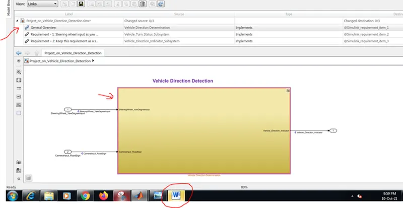
all the requirements are tagged in order for better understandability, anyone who is reviewing the model or who is trying to update the model can get a clear idea of what logic is used in the system. from the requirement manager, we can see what are all are tagged and the description
General Overview:
Requirement - 1:
Requirement – 2:
- Developing SLDD
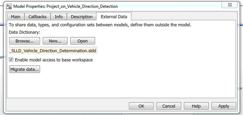
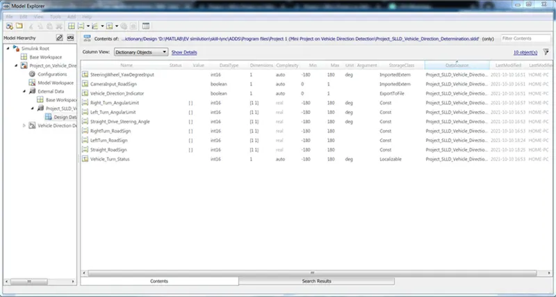
all the inputs, outputs, calibration parameters are saved in SLDD so while simulation the model takes all the values and its parameters from the Simulink Data Dictionary
- Signal Resolution for inputs and outputs
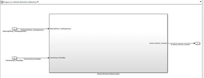
the inputs and output signals are resolved so the signals will take the values from sldd and pass them to the logical blocks. Otherwise, it may take some junk values if it is unresolved
- Model Update.
The model update is done by Ctrl-D. this is done to check for any static errors. If there are no errors coming the model is working fine without any errors.
- Simulation
The model is simulated too for checking for errors and warmings
- Configuration Parameter Update
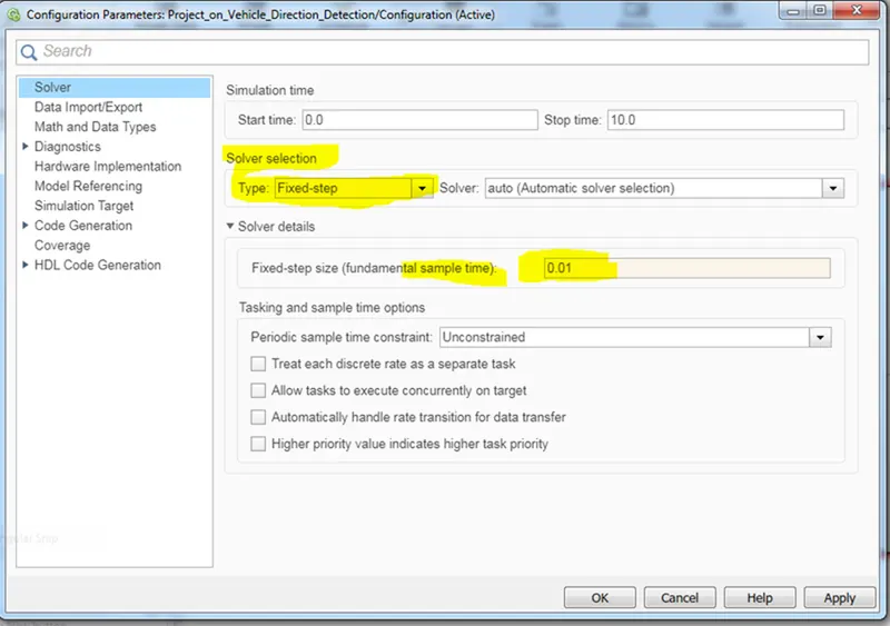
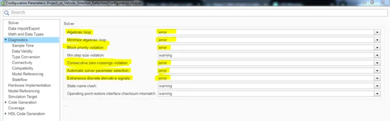
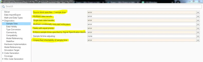
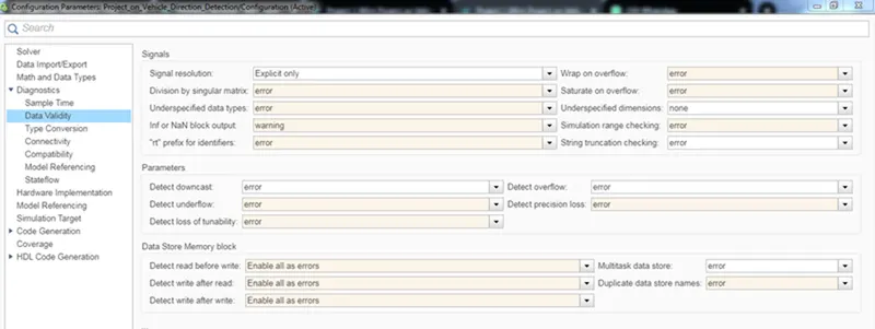
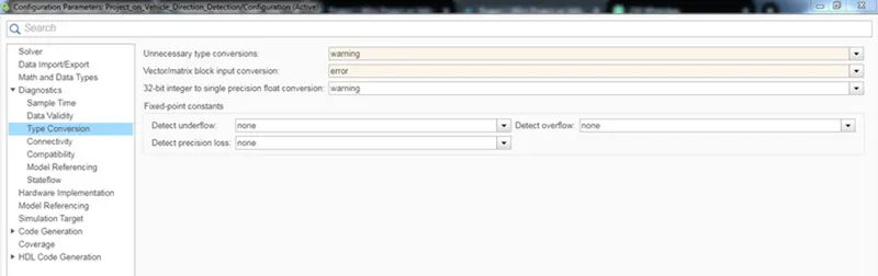
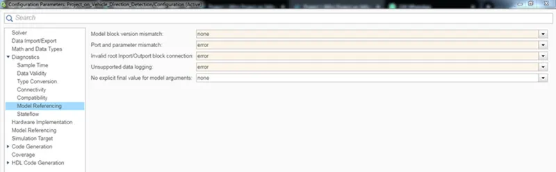
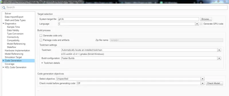
Various configuration parameters are updated as per the code generation the solver type should be fix for code generation
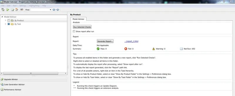
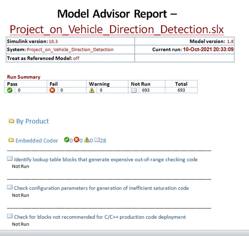
Model Advisory Report
By running the model advisor tool, we can see commonly made modelling errors.
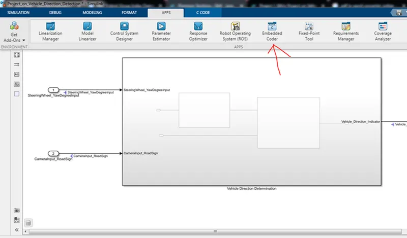
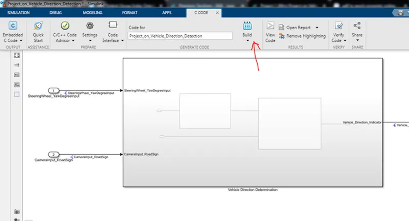
9 Code generation
build model for generating code
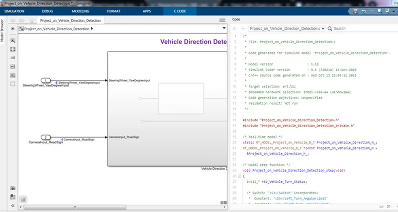
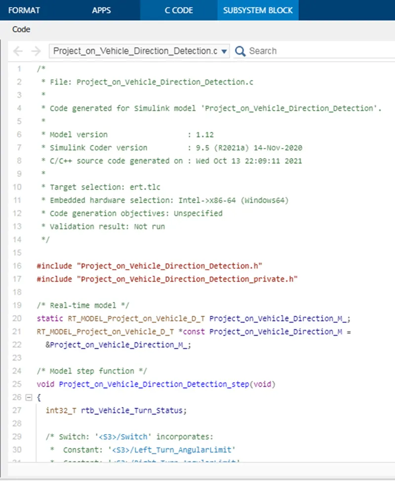
Generated Code :
/*
* File: Project_on_Vehicle_Direction_Detection.c
*
* Code generated for Simulink model 'Project_on_Vehicle_Direction_Detection'.
*
* Model version : 1.12
* Simulink Coder version : 9.5 (R2021a) 14-Nov-2020
* C/C++ source code generated on : Wed Oct 13 22:09:11 2021
*
* Target selection: ert.tlc
* Embedded hardware selection: Intel->x86-64 (Windows64)
* Code generation objectives: Unspecified
* Validation result: Not run
*/
#include "Project_on_Vehicle_Direction_Detection.h"
#include "Project_on_Vehicle_Direction_Detection_private.h"
/* Real-time model */
static RT_MODEL_Project_on_Vehicle_D_T Project_on_Vehicle_Direction_M_;
RT_MODEL_Project_on_Vehicle_D_T *const Project_on_Vehicle_Direction_M =
&Project_on_Vehicle_Direction_M_;
/* Model step function */
void Project_on_Vehicle_Direction_Detection_step(void)
{
int32_T rtb_Vehicle_Turn_Status;
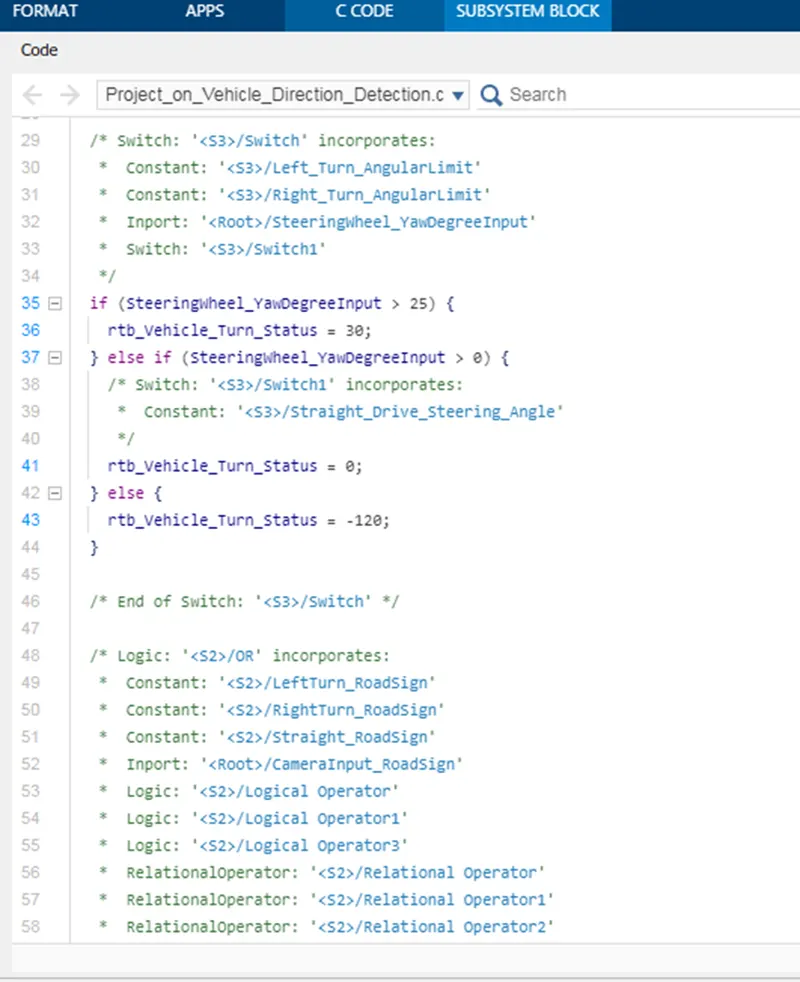
/* Switch: '<S3>/Switch' incorporates:
* Constant: '<S3>/Left_Turn_AngularLimit'
* Constant: '<S3>/Right_Turn_AngularLimit'
* Inport: '<Root>/SteeringWheel_YawDegreeInput'
* Switch: '<S3>/Switch1'
*/
if (SteeringWheel_YawDegreeInput > 25) {
rtb_Vehicle_Turn_Status = 30;
} else if (SteeringWheel_YawDegreeInput > 0) {
/* Switch: '<S3>/Switch1' incorporates:
* Constant: '<S3>/Straight_Drive_Steering_Angle'
*/
rtb_Vehicle_Turn_Status = 0;
} else {
rtb_Vehicle_Turn_Status = -120;
}
/* End of Switch: '<S3>/Switch' */
/* Logic: '<S2>/OR' incorporates:
* Constant: '<S2>/LeftTurn_RoadSign'
* Constant: '<S2>/RightTurn_RoadSign'
* Constant: '<S2>/Straight_RoadSign'
* Inport: '<Root>/CameraInput_RoadSign'
* Logic: '<S2>/Logical Operator'
* Logic: '<S2>/Logical Operator1'
* Logic: '<S2>/Logical Operator3'
* RelationalOperator: '<S2>/Relational Operator'
* RelationalOperator: '<S2>/Relational Operator1'
* RelationalOperator: '<S2>/Relational Operator2'
*/
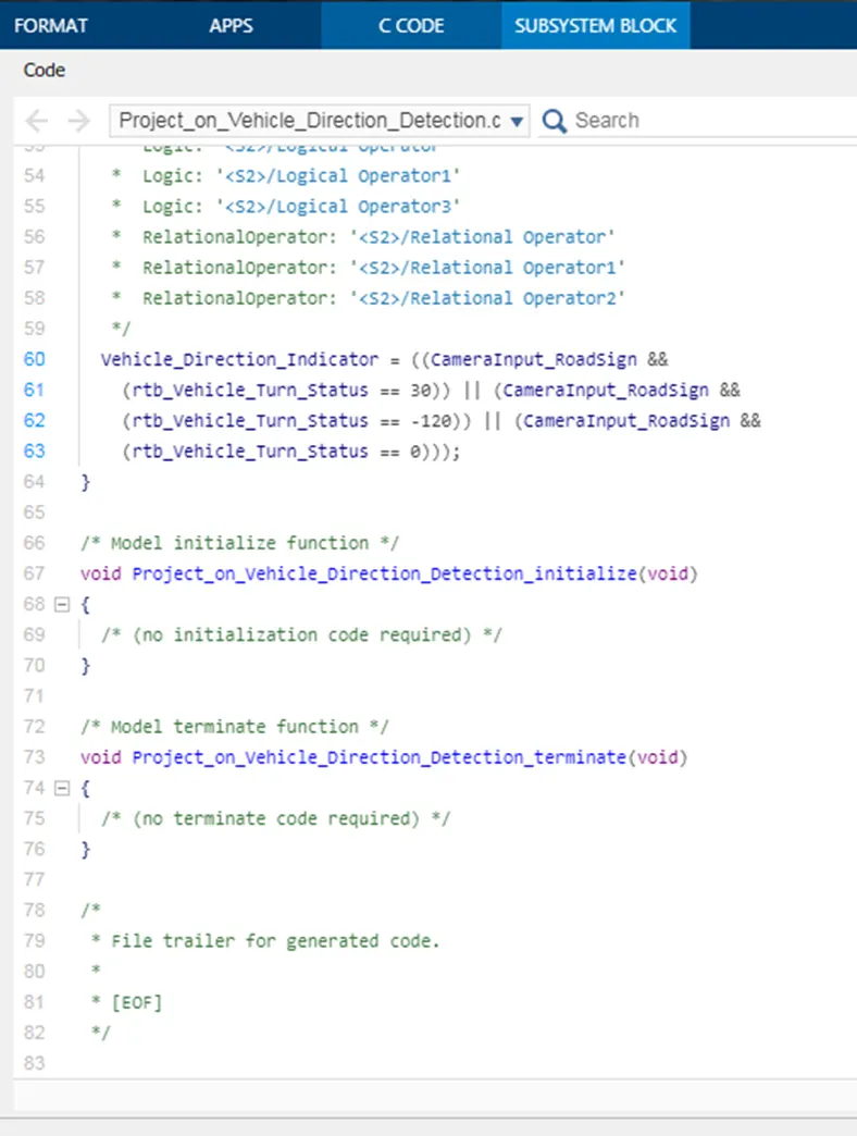
Vehicle_Direction_Indicator = ((CameraInput_RoadSign &&
(rtb_Vehicle_Turn_Status == 30)) || (CameraInput_RoadSign &&
(rtb_Vehicle_Turn_Status == -120)) || (CameraInput_RoadSign &&
(rtb_Vehicle_Turn_Status == 0)));
}
/* Model initialize function */
void Project_on_Vehicle_Direction_Detection_initialize(void)
{
/* (no initialization code required) */
}
/* Model terminate function */
void Project_on_Vehicle_Direction_Detection_terminate(void)
{
/* (no terminate code required) */
}
/*
* File trailer for generated code.
*
* [EOF]
*/
/*
* File trailer for generated code.
*
* [EOF]
*/
Result
The vehicle direction determination is modelled as per the requirement, all the signals are defined in Simulink data dictionary. All input and output signals are resolved and propagated. Updated the model to check for static errors. Run the model advisor tool to see any errors. since there are no errors in Model Advisor Report. Code has been generated using Embedded Coder.
Google Drive link for model and sldd file:https://drive.google.com/drive/folders/15W0EdGCUcj_qmMRrMmTxVT4Z6N1XAYBL?usp=sharing