Week-7 Challenge: DC Motor Control
AIM:-
- How induction motor operation is similar to the clutch?
- Calculate the starting time of a drive with the following parameters:
J=10 kg-m2,
T = 15 + 0.5wm
Tl=5+0.6ωm
- A drive has the following equations for motor and load torques:
Tm=(1+2ωm)
Tl= 3 √ωm
Obtain the equilibrium points and determine the stability.
- Make a MATLAB script file that will plot speed-torque characteristics for the frequency control method.
Question 1
- How induction motor operation is similar to the clutch?
Induction Motor Operation:
The Induction motor has two main parts. Stator and Rotor Stator is basically 3 coil winding and 3-phase AC power input is given to it. The Winding passes through slots of the stator, which are made by thin and highly permeable steel laminations inside a steel or cast-iron frame. When the 3-phase current passes through windings and it produces a Rotating magnetic field. This Rotating Magnetic field is causing the rotor to turn. 3 coils are connected 120 degrees apart. A wire carrying current produces a magnetic field around. The rotational Speed of the magnetic field is known as Synchronous Speed(Ns).
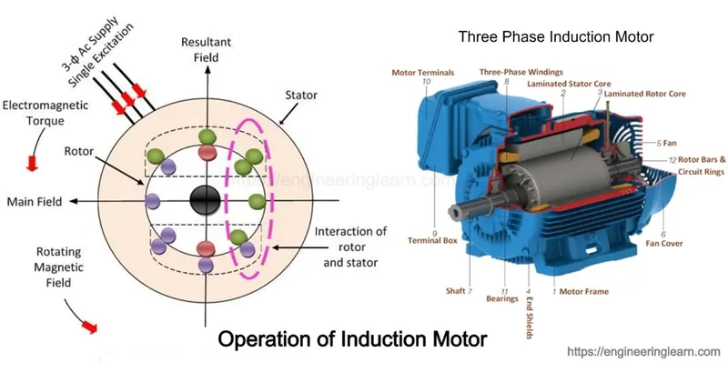
Fig: Key Components of AC Induction Motor
Assume Conductor is placed in the centre of 3 windings Magnetic field will vary, emf will be induced in the loop. An EMF will produce current in the loop. An electro-Magnetic force is produced on the loop and the loop was start to rotate. The same phenomenon occurs in the Induction motor as well. Instead of loop squirrel, a cage rotor is used in Induction motor.
3-phase AC power input is passing through the stator produces a magnetic field and current will be induced in the bars of the squirrel cage. So the rotor starts to rotate. That's why it is an Induction motor, Electricity is induced on the rotor with help of Electromagnetic induction rather than a direct connection.
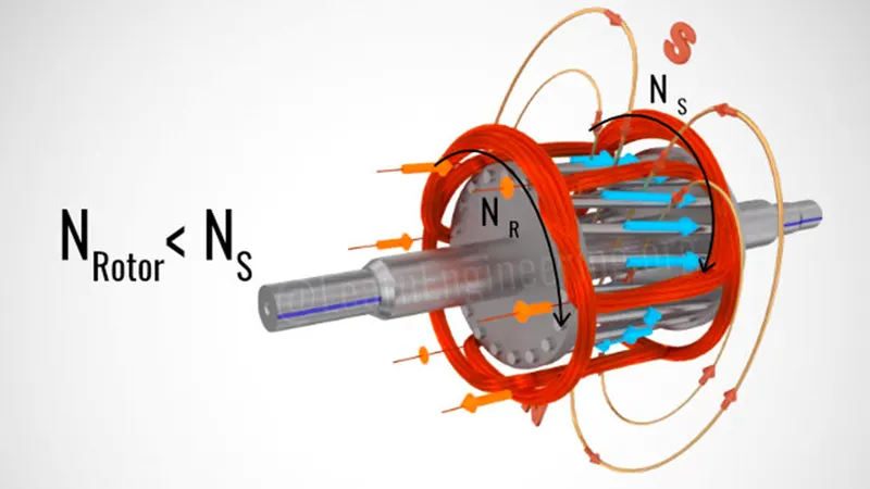
Fig: Rotating Magnetic field with Squirrel cage rotor
Feeding At Both Magnetic field and Rotor are rotating, When the rotor and Magnetic field both are rotating at the same speed, the magnetic field will never cut the loop. Thus, there will not be any induced EMF and Current. This translates zero force of the rotor part and the rotor will gradually slow down. As it slows down, the magnetic field will cut the rotor loop, so induced EMF and current rise again and the rotor will then speed up. The rotor will never be caught up to the speed of the magnetic field. The rotor will rotate at a specific speed that is slightly less than the synchronous speed (Ns). The difference between the Synchronous Speed (Ns) and Rotor Speed (Nr) is known as Slip
Slip=(Ns-Nr)/Ns
Ns=Synchronous Speed,
Nr=Rotor or Motor Speed.
Sometimes, Ns-Nr is called Slip
speed Obviously Rotar or Motor speed is
Nr-Ns(1-s).......Eqn(1)
It may be kept in mind revolving flux is rotating synchronously relative to the stator(i.e., stationary space) but at a slip speed relative to the motor.
Induction Motors do not require permanent magnets, Brushes Commutator rings. Position sensors like other machine mechanical parts Induction motor are also Self Started. The main advantage is Induction motor Speed can control easily by controlling the input power of Frequency
Clutch Operation:
A Clutch is a mechanical device that engages and disengages power transmission especially from the driving shaft to the driven shaft is the simplest application Clutch connect and disconnect two rotating shafts.
An Electromagnetic clutch is a clutch la mechanism for transmitting rotation) that is engaged and disengaged by an electromagnetic actuator. In this type of clutch free-wheel consists of winding The current supplied to the winding from battery or dynamo
AC Induction motor is coupled to an eddy current clutch, also known generally as Magnetic drive, eddy current clutch or magnetic clutch, is an electro-mechanical variable speed drive that us
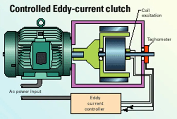
Fig: Eddy Current clutch used in AC Induction Motor
Eddy current clutches are driven at a constant speed by an AC induction motor. The AC motor interacts with an electromagnetic clutch that controls both the torque and speed that is transferred to the driven load. The clutch itself is installed between the constant. speed AC motor and the equipment being driven The clutch controller governs the amount of power that the clutch receives (which is separate from the AC motor power). Included as part of the magnetic rotor is a direct-current (DC) excitation coil that is regulated by the clutch controller. The magnetic rotor combined with the DC excitation coil serves as the electromagnetic coupling that varies the output speed and torque of the clutch's output rotor and shaft
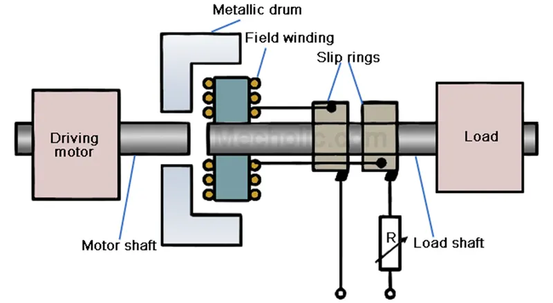
Fig: Eddy Current Clutch Working Operation
A rotating drum (sometimes called a ring) is coupled directly to the Driveshaft (shaft of the motor) and rotates at a constant speed A Rotor (contains Electromagnetic coils) is coupled directly to the Driven Shaft. The Speed of the clutch can be controlled by varying the amount of direct current applied to the rotor. Since the Output Speed (w2) is determined by the amount of slip between the rotor and drum.
Slip=(w1-w2)/w1
w1=Drive Shaft Speed(Input Speed)
w2=Driven Shaft Speed (Output Speed)
Therefore, the Output speed is
w2=w1(1-s).....Eqn(2)
From Eqn (1) and Eqn (2), we know that the Clutch and Induction motor
Result:
When the direct current is applied to the rotor, the spinning electromagnetic induce eddy currents into the metal drum The induce eddy currents for magnetic poles inside the drum The magnetic fields of the rotor and drum are attracted to each other and clutch tums in the same direction of the motor. The main advantage of the al eddy current clutch is that no mechanical connection between the rotor and drum. Since there is no mechanical connection, there is no friction to produce excessive heat and there is no wear as is the case with mechanical clutches
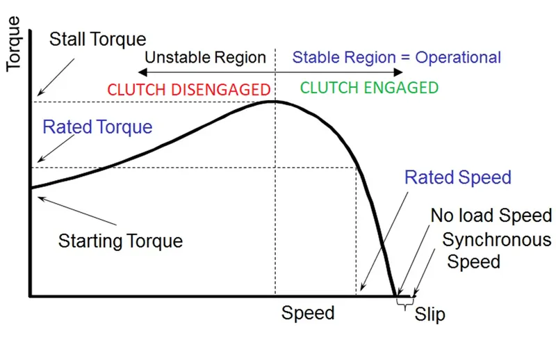
Fig: Torque-Speed Characteristics of Induction Motor
The Speed of the clutch can be controlled by varying the amount of direct current applied to the rotor Since the Output Speed is determined by the amount of slip between the rotor and drum When a load is added, the slip will become greater and causing a decrease in speed. This can be compensated by increasing the amount of direct current applied to the motor. In the State region, the clutch is fully engaged to transfer 100% efficient as there is no related slip and in the Unstable region Clutch is disengaged.
Question 2
- Calculate the starting time of a drive with the following parameters:
J=10 kg-m^2,
T = 15 + 0.5ωm
Tl=5+0.6ωm
Given data:
J=10 kg-m^2,
T = 15 + 0.5ωm
Tl=5+0.6ωm
To find:
To Calculate Starting Time of drive with given parameters
Solution:
By using Motor Torque and Load Torque equation. Constant Speed (equilibrium points) will be calculated
Method =1
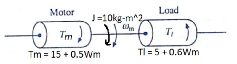
Equivalent Motor Load System
For finding equilibriurn point or Constant Speedlum.
Motor Torque(Tm) =Load Torque(Tl)
15 + 0.5ωm=5+0.6ωm
15-5+0.5ωm=0.6ωm
10+0.5ωm=0.6ωm
10=0.6ωm-0.5ωm
10=0.1ωm
10/0.1=ωm
100=ωm
ωm=100 rad/s
Using Another Method for finding Equilibrium Paint or Constant Speed (wm) is Verified by using MATLAB Program
Method =2
clear all
close all
clc
w=linspace(0,200);
Tm=15+(0.5*w);
Tl=5+(0.6*w);
plot (w, Tm)
hold on
plot (w, Tl)
xlabel("Speed(rad/s)")
ylabel("Tarque(N-m)")
title("Calculating Equilibrium point")
legend('Motor Torque','Load Torque')
grid on
The information for the above MATLAB Program
Step=1 Giving Input of Speed(w). Motor Torque Equation (Tm) and Load Torque Equation(Tl)
Step=2 For finding Constant Speed(ωm) or Equilibrium point. Use the "plot" command to plot Speed(w) with Motor Torque(Tm) and Speed(w) with Load Torque(Tl)
Step=3 Use the "hold on" command between two "plot" commands to plot the results in a Single plot window
Step=4 Use "xlabel","ylabel","title","legend" and "gird on" Command for Proper identification of output results
Step=5 Run the Program to get the Output Plot Results
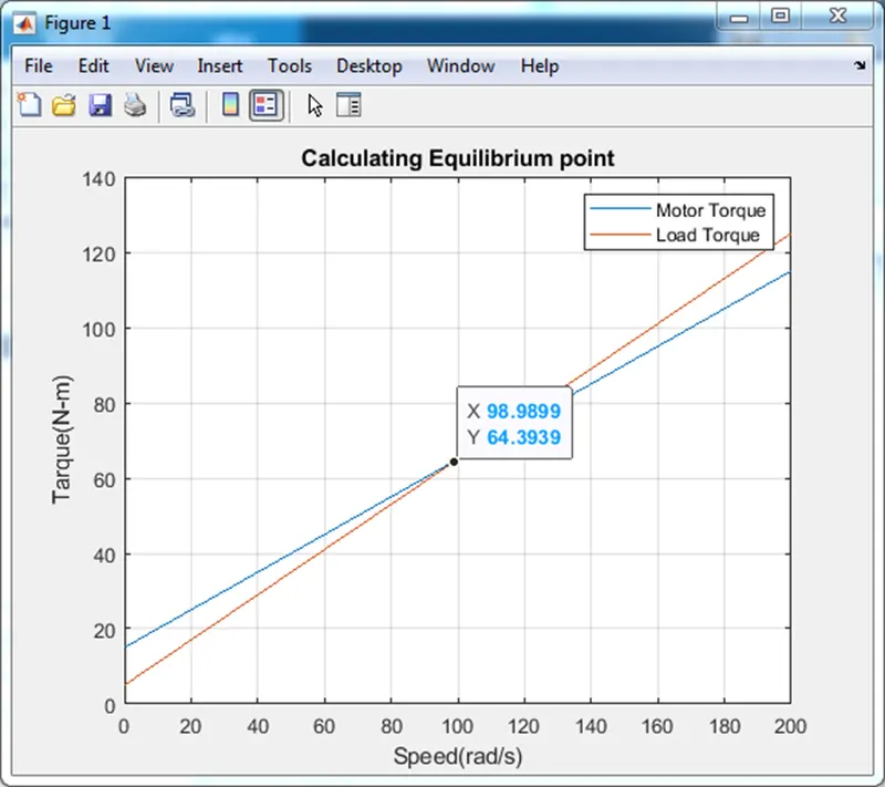
From the above plot, we obtain two equilibrium points. ωm=98.9899=100 rad/s
After finding Constant Speed(ωm), to find the Starting time to reach constant angular speed. For finding Starting Time of drive Solve the Steady State Stability Equation which is related to Newton second law(F=m*a),
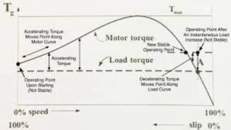
Fig (A): Torque-Speed Characteristic Stability Analysis
Here, Force(F) is referred to as Torque(T) which is Motor Torque(Tm) and Load Torque(Tl). In Linear motion consider Mass(m) and here a rotational motion so considered Moment of Inertia (J) and linear Acceleration(a) is dv/dt and in angular acceleration is dw/dt
Steady-State Stability equation of induction motor is
Tm-Tl=J(dw/dt) ........ Eqn(A)
Substitute the Given input parameters in above Eqn(A).
(15 + (0.5ωm))- (5+(0.6ωm))=10*(dw/dt)
15-5 + 0.5ωm- 0.6ωm=10*(dw/dt)
10-0.1*ωm=10*(dw/dt)
(dw/dt)=10-(0.1*ωm)/10
(dw/dt)=10-(0.1*ωm)/10
(dw/dt)=1-(0.01*ωm)......eqn(i)
Rearranging the above equation in terms of change in time(dt) with respect to change in speed(dw) for finding the Starting time of the drive.
(dt/dw)=(1/(1-(0.01*ωm)))
By referring to fig(A) Torque-Speed Characteristic Stability Analysis when motor reaching the steady-state speed slip will occur.
Here Assuming 5% of slip is occurring at Constant Speed(ωm)
Therefore, Integrating the above differential equation with 0 to 95 rad/s boundary limits, we get the starting time of the drive.
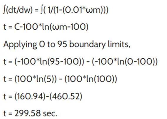
For the given, input parameter motor torque(Tm), load torque(Tl) and movement of inertia(j) starting time of drive is t=299.58 sec nearly equal to t=300 sec
Question 3
- A drive has the following equations for motor and load torques:
Tm=(1+2ωm)
Tl= 3 √ωm
Obtain the equilibrium points and determine the stability.
Given:
Tm=(1+2ωm)
Tl= 3 √ωm
To Find:
Obtain the equilibrium points and determine the stability.
Solution:
- Finding Equilibrium Point:
For Obtaining Equilibrium point. Refer to STUDY-2 and the same steps to be followed
Motor Torque(Tm) - Load Torque(TL) MATLAB Program for Obtaining Equilibrium Point:
clear all
close all
clc
w=linspace(0,2);
Tm=1+(2*w);
Tl=3*sqrt(w);
plot (w, Tm)
hold on
plot (w, Tl)
xlabel(" Speed(rad/s)")
ylabel(" Tarque(N-m)")
title("Calculating Equilibrium point")
legend('Motor Torque','Load Torque')
grid on
The explanation for the above MATLAB Program
Step=1 Giving Input of Speed(w). Motor Torque Equation (Tm) and Load Torque Equation(Tl)
Step=2 For finding Constant Speed(ωm) or Equilibrium point. Use the "plot" command to plot Speed(w) with Motor Torque(Tm) and Speed(w) with Load Torque(Tl)
Step=3 Use the "hold on" command between two "plot" commands to plot the results in a Single plot window
Step=4 Use "xlabel","ylabel","title","legend" and "gird on" Command for Proper identification of output results
Step=5 Run the Program to get the Output Plot Results
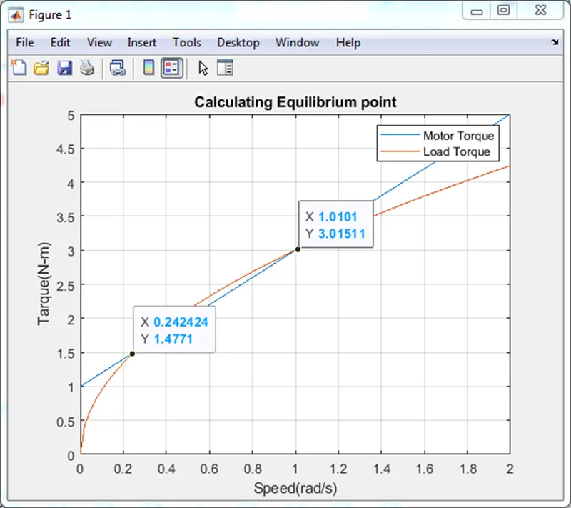
From the above plot, we obtain two equilibrium points. ωm=0.242424 & 1.0101 rad/s
Determining the Stability:
The motor that is going to drive the load sufficiently is known as Stability. That is the motor has enough power to drive the load If the motor does not have enough power or the load is running in another region of Characteristic s known as Unstable operation and the motor is never going to satisfy the load. For Determining the Stability, it should satisfy the condition for Stability
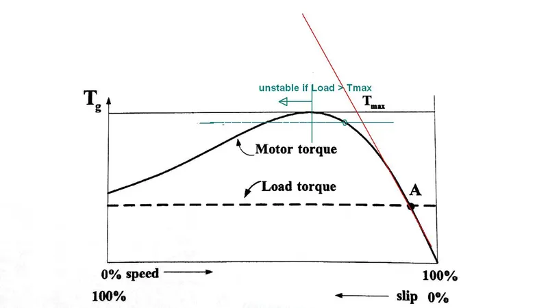
Fig: Torque-Speed Characteristic Stability Analysis of a drive
Stability theory tells that if a change in Load torque(dTl) vs Change in Positive Speed(dωm) and its difference with change in motor torque(dTm) vs same Change in Positive Speed(dωm) should be greater than zero for the motor drive system to become stable.
Condition for Stability.
(dTl/dωm)-(dTm/dωm)>0.............eqn(a)
Condition-(i)
if dωm>0, Tl> Tm
while Speed is increasing, Load torque(Tl) will be greater than Motor Torque(Tm)
Condition-(ii)
if dωm<0, Tl <Tm
while Speed is decreasing, Load torque(Tl) will be lesser than Motor Torque(Tm)
Substituting the Given Load Torque(TI) and Motor Torque(Tm)
equation in eqn(a) condition for Stability.
(dTl/dωm)-(dTm/dωm) > 0
[d(3 √ωm)/dωm]-[d(1+2ωm)/dωm]>0
By differentiating the above equation, we get
[3/(2√ωm)]-[0+2]
[3/(2√ωm)]-2 >0......eqn(b)
Case(i)-substitute ωm=0.242424 rad/s in above eqn (b)
[3/(2 √0.242424)]-2>0
[3/0.9797]-2>0
3.062-2>0
1.062 >0 It satisfied
the above condition
Case(i)-substitute ωm=1.0101 rad/s in above eqn(b)
[3/(2√ωm)]-2 >0......eqn(b)
[3/(2√1.0101)]-2 >0
[3/2.01]-2 >0
1.5-2 >0
-0.5>0
It is not satisfied the above equation
Result
Case (i)satisfies the conditions for stability, so ωm=0.24 rad/s is the stability of a drive (motor has going to drive the load sufficiently)
Question 4
- Make a MATLAB script file that will plot speed-torque characteristics for the frequency control method.
solution:-
What is the frequency control method:-
A three-phase induction motor is basically a constant speed motor so it’s somewhat difficult to control its speed.
The speed control of the induction motor is done at the cost of a decrease in efficiency and low electrical power factor.
Before discussing the methods to control the speed of the three-phase induction motor one should know the basic formulas of speed and torque of the three-phase induction motor as the methods of speed control depends upon these formulas.
Synchronous Speed

Where, f = frequency and P is the number of poles
The speed of induction motor is given by,
Where,
N is the speed of the rotor of an induction motor,
Ns is the synchronous speed,
S is the slip.
The torque produced by the three-phase induction motor is given by,

When the rotor is at the standstill slip, s is one.
So the equation of torque is,

Where,
E2 is the rotor emf
Ns is the synchronous speed
R2 is the rotor resistance
X2 is the rotor inductive reactance
Making a MATLAB script file for the speed-torque characteristics for the frequency control method.
MATLAB script file as shown in below
clear all
close all
clc
V= 230/sqrt(3);
no.of_phase=3;
poles=4;
R1=0.095;
R2=0.23;
X1=0.680;
X2=0.672;
Xm=18.7;
Zequiv=(1i*Xm*(R1+1i*X1))/(R1+1i*(X1+Xm));
Req=real(Zequiv);
Ieq=imag(Zequiv);
Veq=abs(V*1i*Xm)/(R1+1i*(X1+Xm));
Vf=linspace(10,50,4);
% ( Vf-variable frequency)
for i=1:length(Vf)
omega_ms=120*Vf(i)/poles;
omega=4*pi*Vf(i)/poles;
for n=1:200
s(n)= n/200; %slip
rpm(n)=omega_ms *(1-s(n)); %rpm
I2=abs(Veq/(Zequiv+1i*X2+R2/s(n))); %I2
T(n)=no.of_phase*I2^2*R2/(s(n)*omega);
end
plot(rpm,T,'linewidth',2)
hold on
end
axis([0 1500,0 600])
xlabel('motor speed(rpm)')
ylabel('torque(N-m)')
grid on
legend('10HZ','20HZ','30HZ','40HZ')
Workspace:-
Output:- speed-torque characteristics