Project 1 (Mini Project on Vehicle Direction Detection
- Development of MATLAB Simulink model as per requirement.
- Tag the requirements to the simulink model; tagging requirement 1 & requirement 2 to their corresponding subsystems is fine.
- MBD compliant changes, Data Dictionary creation & code generation is added advantage, and that is not scope of this project.
- If choosing code generation, Storage class for Input signals: ImportedExtern; Storage class for Output signal: Export to File; Storage class for local signals: localizable; Storage class for calibration signals: Const.
- Choose sample time for all signals as 0.01s
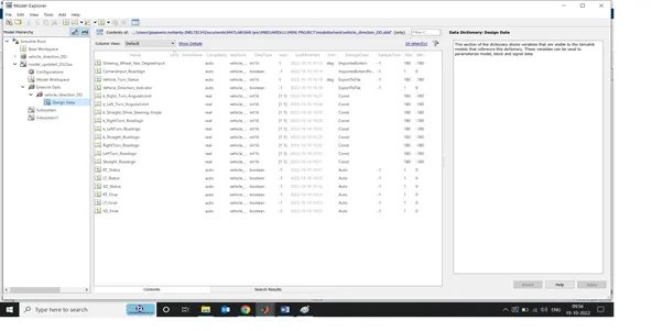
- As per the requirement of the problem statement a data dictionary is being created.
The sample time for all the signals are set to be 0.01s
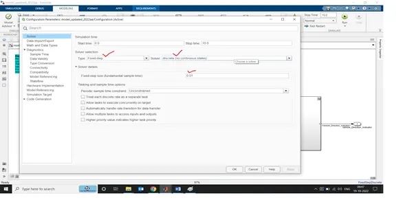
The solver is selected to be fixed discrete type.
- As per MBD guideline, the signals are resolved/ propagated according to their origin.
- Requirement files are tagged for easy reference.
- A description is provided for the ease of understanding of each subsystem.
- In and out ports are named appropriately
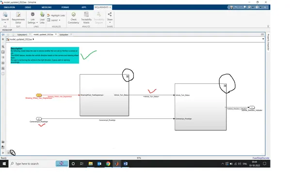
STEPS FOR REQUIREMENT TAGGING:
- Open the word/excel file in which the requirements are mentioned. Select the heading of the requirement. (do not close the file)
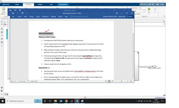
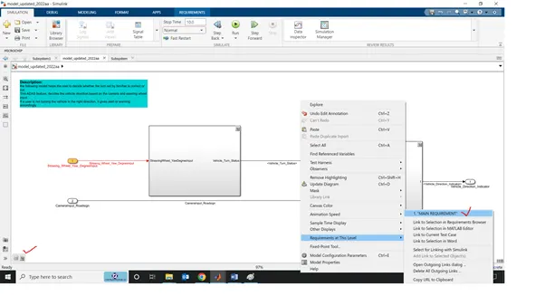
- Right click on the model where you want to tag the requirement. Select Requirements at This Level --> Link to Selection in Word (if yours is a word file)
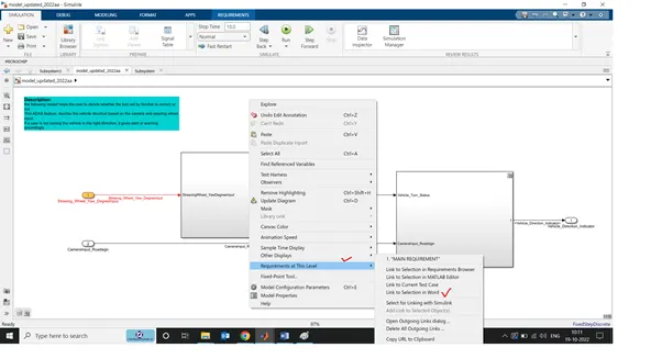
- A successful tagging of requirement file can be verified from the left below corner. Also once you right click and go to “Select Requirements at This Level”, you can see the heading is on the top of the list showing which file it is being tagged.
Requirement - 1:
- Steering wheel input as yaw rate (Signal name: SteeringWheel_YawDegreeInput) is the input for this system.
- This is compared against 3 angular values, one each for left turn, right turn & straight drive (Calibration Values: Right_Turn_AngularLimit, Left_Turn_AngularLimit, Straight_Drive_Steering_Angle) to say which specific direction the steering wheel is turning towards.
- Use switch blocks to compare & develop this requirement. Keep this requirement in a subsystem & output of this requirement is a local signal (Signal Name: Vehicle_Turn_Status).
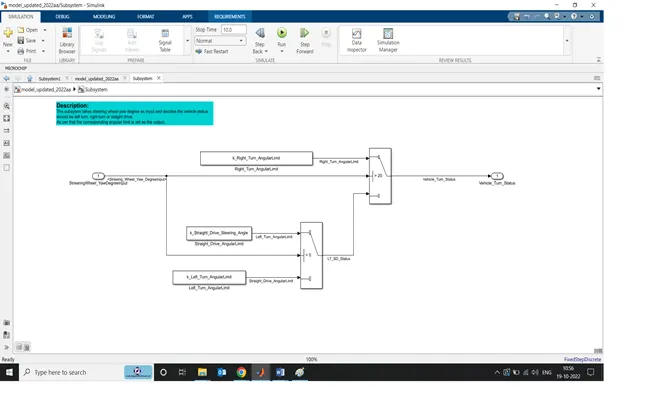
In this subsystem, the steering wheel yaw position is taken as input and it is being compared with the three predefined values to decide the ideal wheel rotation direction.
The logic is being implemented using switch cases. If the input is more than 20 deg (threshold for right turn) then the command should be given to turn right.
If the input is between 0-20 deg, the driver should drive straight and if the input is negative it should take a left turn.
All the constant values are defined in the SLDD file with appropriate initial values, data types and storage class.
The output vehicle turn status is given as an input to the next subsystem.
Requirement – 2:
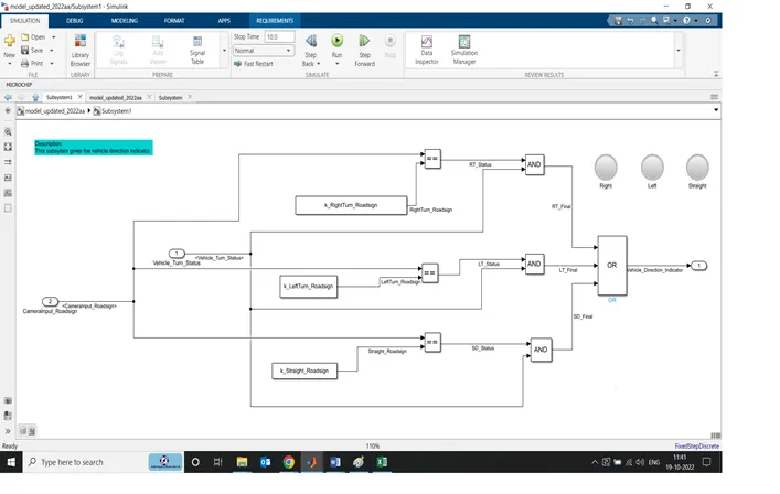
- Keep this requirement as a separate subsystem. Inputs to this requirement are local signal from requirement 1 (Signal Name: Vehicle_Turn_Status) & an input signal from camera (Signal Name: CameraInput_RoadSign), which confirms the occurrence of a road sign.
- Signal Vehicle_Turn_Status is compared against calibration values (Calibration Values: RightTurn_RoadSign, LeftTurn_RoadSign, Straight_RoadSign), if each of them is found equal, then each of the three corresponding output is compared against the camera input signal,
- Using a logical operator block, only one among them is finally given as output signal (Signal Name: Vehicle_Direction_Indicator).
Signals & Calibration Data List:
|
Signal / Calibration Name |
Signal Type |
Data Type |
Dimension |
Min |
Max |
Initial Value |
Units |
|
SteeringWheel_YawDegreeInput |
Input |
Int16 |
1 |
-180 |
180 |
- |
Deg |
|
CameraInput_RoadSign |
Input |
Boolean |
1 |
0 |
1 |
- |
- |
|
Vehicle_Turn_Status |
Local |
Int16 |
1 |
-180 |
180 |
- |
Deg |
|
Right_Turn_AngularLimit |
Calibration |
Int16 |
[1 1] |
-180 |
180 |
30 |
Deg |
|
Left_Turn_AngularLimit |
Calibration |
Int16 |
[1 1] |
-180 |
180 |
-120 |
Deg |
|
Straight_Drive_Steering_Angle |
Calibration |
Int16 |
[1 1] |
-180 |
180 |
0 |
Deg |
|
RightTurn_RoadSign |
Calibration |
Int16 |
[1 1] |
-180 |
180 |
30 |
|
|
LeftTurn_RoadSign |
Calibration |
Int16 |
[1 1] |
-180 |
180 |
-120 |
|
|
Straight_RoadSign |
Calibration |
Int16 |
[1 1] |
-180 |
180 |
0 |
|
|
Vehicle_Direction_Indicator |
Output |
Boolean |
1 |
0 |
1 |
- |
- |
This subsystem takes vehicle turn status and camera Input road sign as two inputs.
At the first place, input from camera for road sign is being compared with the predefined values for left/right /straight road sign.
In the next step, the output of the previous comparison is passed through an and gate along with the vehicle turn status signal from the previous subsystem.
Finally, as per the road sign and the steering wheel position, the vehicle direction indicator is made to glow. For each case there is one indicator that will successfully glow informing the driver the correct direction to turn.
As per the MAAB guidelines,
- the flow direction of the signal is from left to right.
- The AND, comparison blocks are square in shape.
- Signals are resolved and propagated properly.
- In and out ports are named suitably.
- SLDD is also created with proper signal characteristics.
- Requirement file is tagged.
- Small description of total model and each subsystem is attached.