Project 1 (Mini Project on Vehicle Direction Detection
Mini Project - Vehicle Direction Determination
Simulink model:
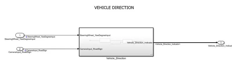
We have created Subsystem. After creating subsystem we have requirement1 and requirement2 port 1 (Logic Now in the Subsystem) After this.
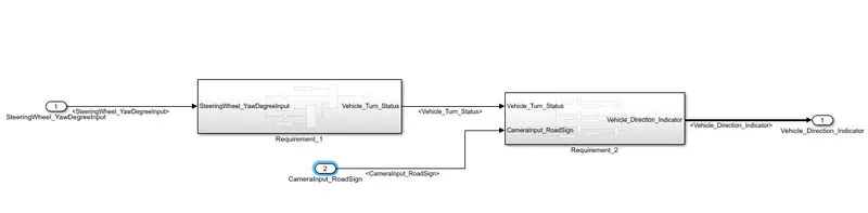
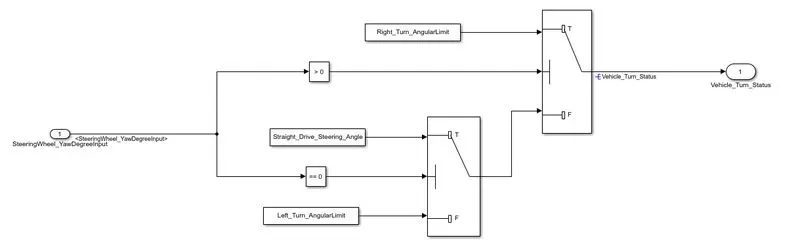
Requirement1
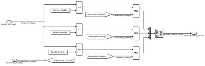
Requirement2
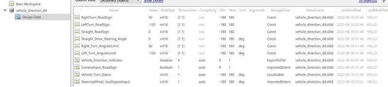
The SLDD_file is created to store the calibration values and input and output signals.
Blocks used:
Blocks used to create a model are
Input Blocks: To provide the input signals
Output Blocks: To send the output signals
Constant Blocks: To define the calibration values
Compare to constant block: Determine how a signal compares to a constant
Relational operator block: Applies the selected relational operator to the inputs and outputs the result. The top (or left) input corresponds to the first operand.
Logical operator Blocks: OR blocks are used to compare and the road signs with camera input and to get the boolean output.
From block: Receive signals from the Goto block with the specified tag.
Switch Blocks: To compare the input with the calibration values.
Mux Block: To combile the signals
Signal conversion block: Convert a signal to a new type without altering signal values.
Display Block: To display the results
Procedure:
The logic in the Requirement_1 is, If the input is >=20 (because the initial value is 20) the vehicle will take the Right turn, else If the input is not-equal to zero (~=0) the vehicle left_turn, else stright_drive (if the input is equal to zero).
The input yaw rate is given to the middle port of the switch, and the threshold value is 20. If the input is greater than threshold value then the switch will takes the True condition (Right_Turn_AngularLimit) else false condition. In the second switch the threshold value is zero, if the threshold value is not equal to zero then the switch will takes the true condition (Left_Turn_AngularLimit) else takes the false condition (Sitight_Drive steering_Angle). This output from the second switch is given as a false condition to the first switch. And the output for the Requirement_1 is "Vehicle_Turn_Status".
The logic in the Requirement_2 is to compare the "Vehicle_Turn_Status" (Output of Requirement_1) with "RoadSign" and an input signal from camera to get the Vehicle Direction indicaton.
After comparision with "Vehicle_Turn_Status" if each of them is found equal, then each of the three corresponding output is compared against the camera input signal, by using the 'logical OR' Blocks will get the true case and to take only one among them as output, the 'Mux' block is used.
And the final output from the Vehicle_Detection Model will indicates the vehicle_Direction indication.
Next by adding the SLDD_file to the model and by loading the calibration values and input/output values are defined.
By running the simulation will get the vehicle direction.
(MIL) Test Harness
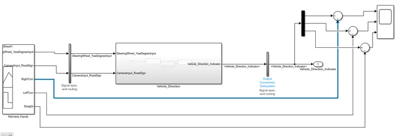
Explanation of Test Harness:
2nd step we have Adjusted in modal setting, solver setting we define the sample time
Now 3rd is to creat the Test Harness just right click on the subsystem and go to the test harness option and choose the creat for subsystem then you will get test harness box and choose signal builder. In Advanced properties, Verification mood is normal.
After creating test harness you will get some block this is inserted by simulink. It will teke care data type conversion. Similarly here at the output may have some data type it will show the output double data type
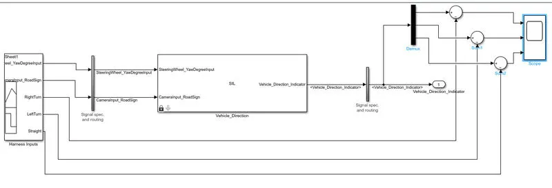
After created (MIL) Test Harness. Than we have created (SIL) Test Harness both Process is same but SIL there was condition to select the setting for subsystem block. To enable parameters for code generation, select ' Treat as atomic unit than creat SIL test harness once you click ok C code generate atomatic in the working folder
There are another option to creat c coder with the help of embedded codder matlab simulink.
Now we have imported the test signals. What we have written in the excel sheet
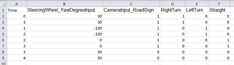
Just open the the signal builder block and in the signal builder block click on the file and go to the import file option and select the test signals and transfer the data from excel sheet(test signals) to signal builder.
What ever you defined input in the excel sheet. Now It is persent in signal builder.
Results
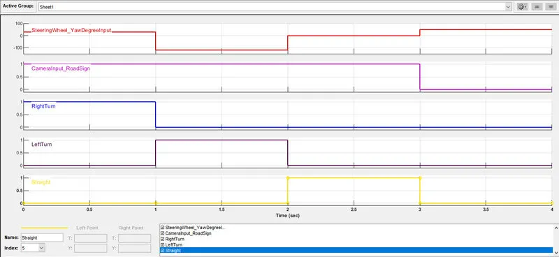
Now you can see the it is taking step way form.These are the expected output.
That mean 0 to next sample define is 0.5 sec. 0 to 0.5 it is taking step way. 0.5 to 1sec. And what ever we define the in the test signals. It is imported into signal builder and show the result.
We have total 8 test signals.
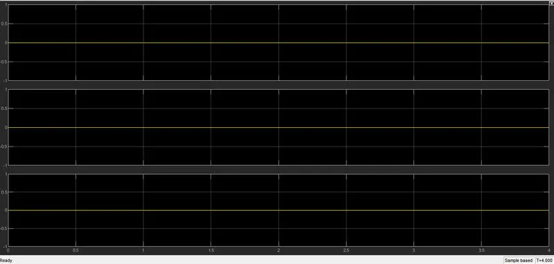
If you compair Actual output with the expected sgnal output diffrent should be 0 throught out the simulation. If the diffrent is 0 it means that actual value match with the expected value at given time.
Conclusion:
Autonomous vehicles consists of various Advance Driver-Assistance System (ADAS) features. Vehicle Driection Detection is one the features of the vehicles.
Hence, created an Simulink model of Vehicle Direction Detection as per the Requirement data.