Project 1 (Mini Project on Vehicle Direction Detection
Aim: To develop the Vehicle Direction Determination model using simulink.
Objective of Mini Project:
- Development of MATLAB Simulink model as per requirement.
- Tag the requirements to the simulink model; tagging requirement 1 & requirement 2 to their corresponding subsystems is fine.
- MBD compliant changes, Data Dictionary creation & code generation is added advantage, and that is not scope of this project.
- If choosing code generation, Storage class for Input signals: ImportedExtern; Storage class for Output signal: Export to File; Storage class for local signals: localizable; Storage class for calibration signals: Const.
- Choose sample time for all signals as 0.01s
Theory :
>> Vehicle Direction Determination:
Identifying the direction of the vehicle is one of the important & diverse features in Autonomous driving & Advanced Driver Assistance Features. This particular sub-feature of identifying the direction of vehicle is basically identifying the direction the vehicle is taking based on the camera input.
- Camera reads the road signs & stores into its memory with unique values for left turn, right turn & straight drive.
- Depending on the direction it is taking, final indication is given to the driver – as an indication if he is driving in the recommended direction or not.
- Vehicle Direction Determination can also be coupled along - side features like GPS systems to identify whether the vehicle is reaching its destination in an optimized manner.
- This sub feature can also be used along with Lane Detection, Highway Warning, Ramp Entry / Exit in Wrong Way Detection etc
Explanation :
As in quetion the signal list is given so as per the given data will create SLDD file y adding the given signals
Signals & Calibration Data List:
|
Signal / Calibration Name |
Signal Type |
Data Type |
Dimension |
Min |
Max |
Initial Value |
Units |
|
SteeringWheel_YawDegreeInput |
Input |
Int16 |
1 |
-180 |
180 |
- |
Deg |
|
CameraInput_RoadSign |
Input |
Boolean |
1 |
0 |
1 |
- |
- |
|
Vehicle_Turn_Status |
Local |
Int16 |
1 |
-180 |
180 |
- |
Deg |
|
Right_Turn_AngularLimit |
Calibration |
Int16 |
[1 1] |
-180 |
180 |
30 |
Deg |
|
Left_Turn_AngularLimit |
Calibration |
Int16 |
[1 1] |
-180 |
180 |
-120 |
Deg |
|
Straight_Drive_Steering_Angle |
Calibration |
Int16 |
[1 1] |
-180 |
180 |
0 |
Deg |
|
RightTurn_RoadSign |
Calibration |
Int16 |
[1 1] |
-180 |
180 |
30 |
|
|
LeftTurn_RoadSign |
Calibration |
Int16 |
[1 1] |
-180 |
180 |
-120 |
|
|
Straight_RoadSign |
Calibration |
Int16 |
[1 1] |
-180 |
180 |
0 |
|
|
Vehicle_Direction_Indicator |
Output |
Boolean |
1 |
0 |
1 |
- |
- |
STEPS TO ADD THE SIGNALS IN SLDD FILE :
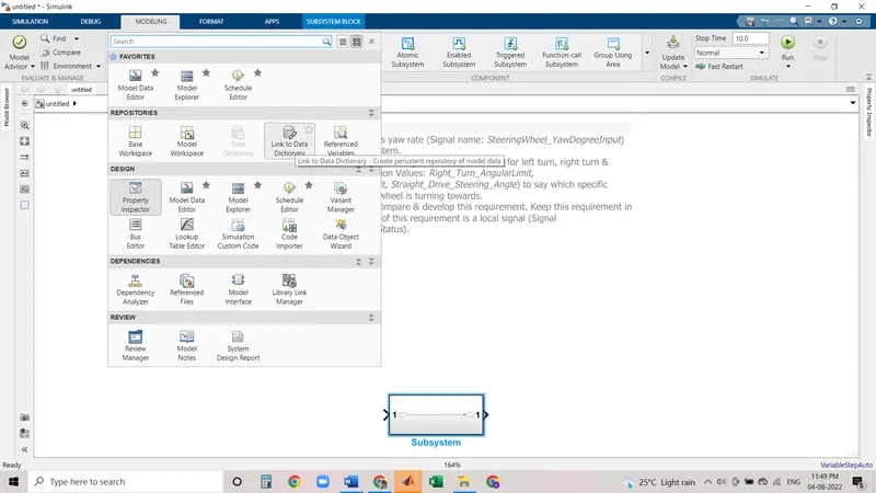
1.GO TO -MODELLING-LINK TO DATA DICTIONARY -
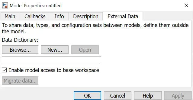
2. NEW FILE -CREATE FILE IN THE FOLDER WHERE YOU HAVE SAVE THE MOEL (CREATE ALL FILES IN SAME FOLDER )FOR BETTRE RESULT WITHOUT ERROR
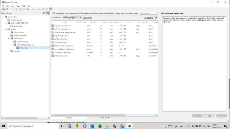
3. now we have to add the signals as we are going to generate the code there is condition given in question as follows
- If choosing code generation, Storage class for Input signals: ImportedExtern; Storage class for Output signal: Export to File; Storage class for local signals: localizable; Storage class for calibration signals: Const.
we add the changes as per the given conditing
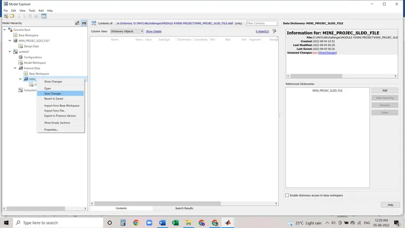
ITS VERY IMPORTANT TO SAVE THE CHANGES IF WE GO BACK THIS SIGNALS WILL NOT SAVED UNLESS UNTIL WE SAVE THEM.
4. ADD THE BLOCKS AS PER THE REQUIRMENT AND MAKES A SEPARTE SUBSYSTEMS OF BOTH REQUIRMENT
Objective of Mini Project:
as per the given requirment 1 we create the model 1:
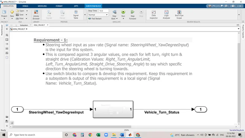
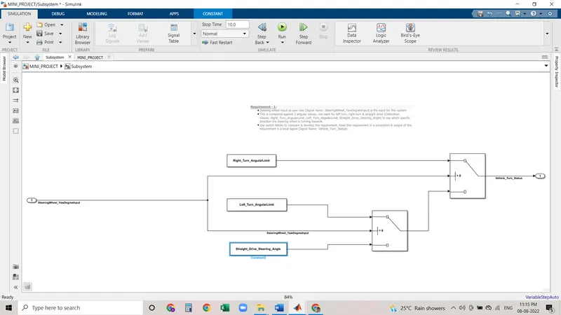
as per the given requirment 2 we create the model :
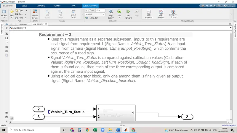
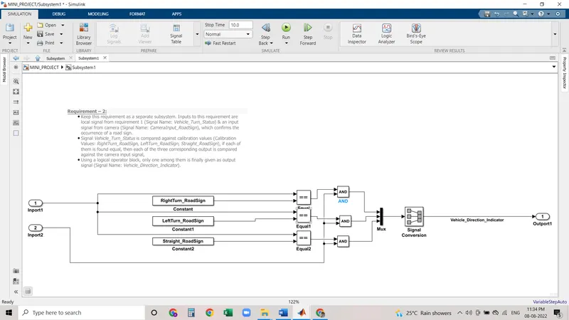
- Tag the requirements to the simulink model; tagging requirement 1 & requirement 2 to their corresponding subsystems is fine.
STEPS TO TAG THE REQUIRMENT :
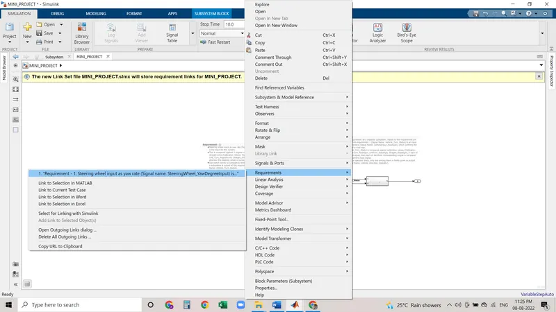
RIGHT CLICK ON SUSBSYSTEM-REQUIRMENT-LINK TO SELECTION IN WORD (FIRST OPEN THE WORD FILE COPY THE REQUIREMENT FROM THE QUESTION AND SELECT THE REQUIRMENT 1 AND FOLOOW THE PROCEDURE .
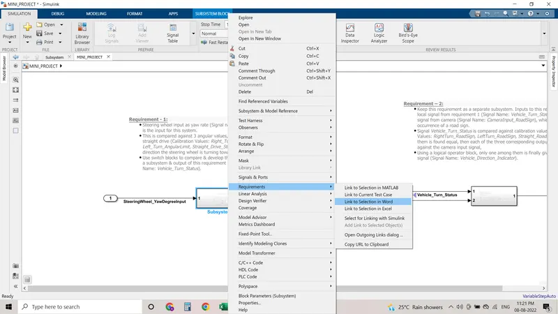
after tagging you can check its tagged or not its shwoing like this means we tagged the requirment 1
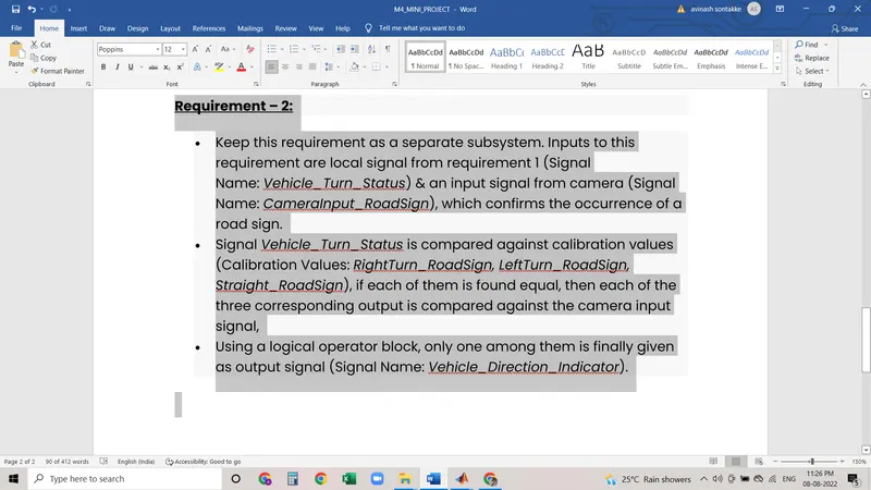
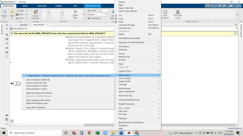
select the question or requirmnet from the word and follow the same procedure to tag requirment 2:
as its showing that subsystem is tagged with requirement:
- MBD compliant changes, Data Dictionary creation & code generation is added advantage, and that is not scope of this project.
as part of MBD compliant we are now giving all bloack names and labellingg of blocks
we are following some steps to give the all block names
select all blocks -right click-format-show block name -on .it will show the all block names
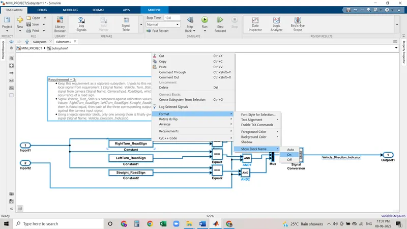
for giving the signal names we are labelling the all labesl :
select the signal line-right click-paste the signal name or write the signal name if it is the first signal -click on -signal name must be resolve so that its cme as main signal
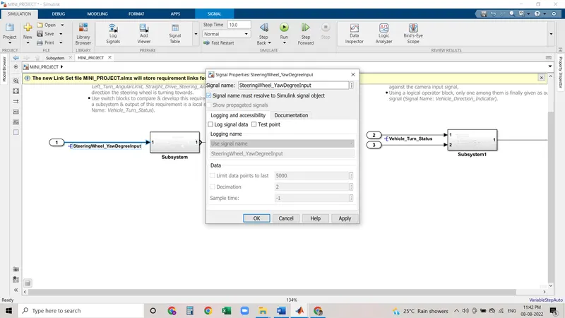
here after completeing labelling it will show the resolved signal with propagated signals
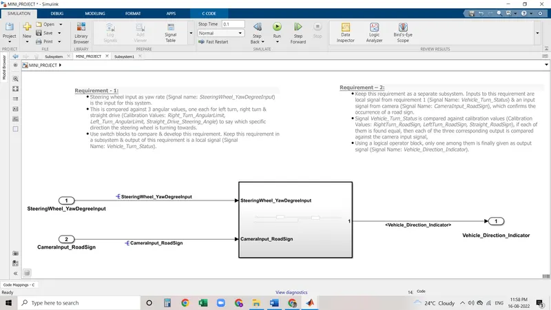
TO GENERATE THE CODES : RIGHT CLICK-BLOCK PARAMETER -CLICK ON TREAT AS ATOAMTIC UNIT
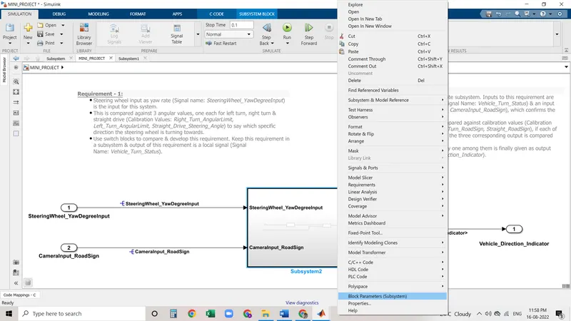
CLICK ON TREAT AS ATOAMTIC UNIT
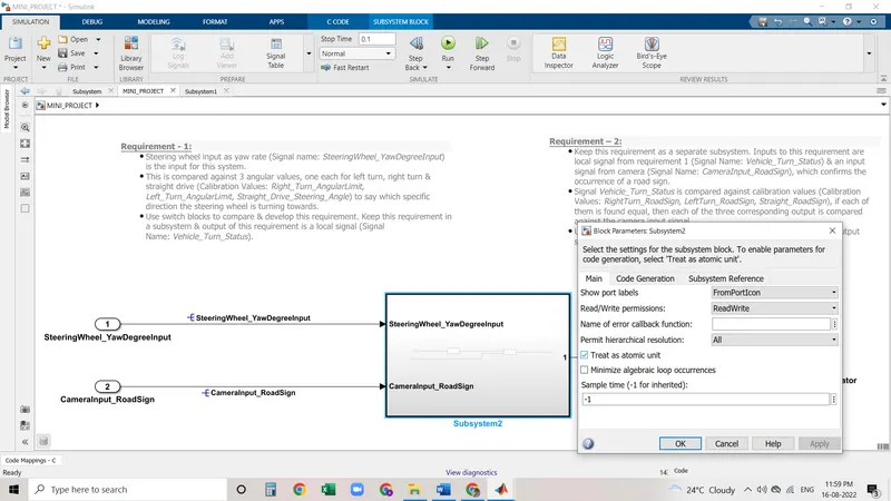
TO GENERATE THE CODE GO TO APPS-EMBEDDED C -GENERATE CODE
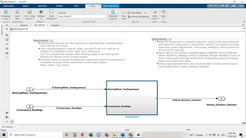
REPORT:
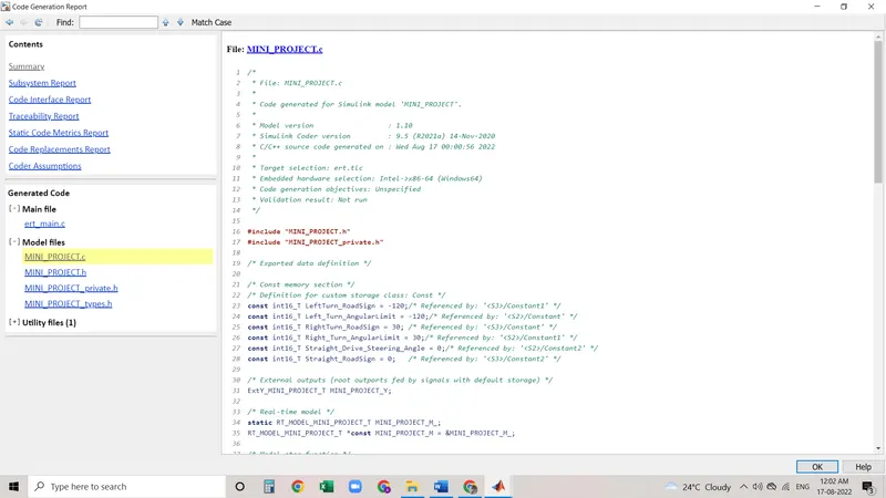
GENERATED C CODE .