Project 1 (Mini Project on Vehicle Direction Detection
EV - 21 MINI PROJECT
AIM :-
To determine the direction of the vehicle in simulink is basically identifying the direction the vehicle is taking based on the camera input and based on the requirements
Objective of the project : -
- Development of MATLAB Simulink model as per requirement.
- Tag the requirements to the simulink model; tagging requirement 1 & requirement 2 to their corresponding subsystems is fine.
- MBD compliant changes, Data Dictionary creation & code generation is added advantage, and that is not scope of this project.
- If choosing code generation, Storage class for Input signals: ImportedExtern Storage class for Output signal: Export to File; Storage class for local signals:Localizable; Storage class for calibration signals: Const
- Choose sample time for all signals as 0.01s
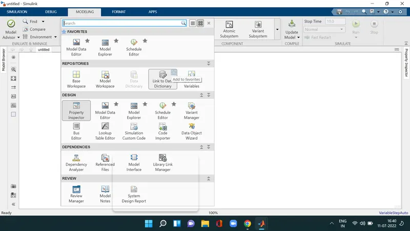
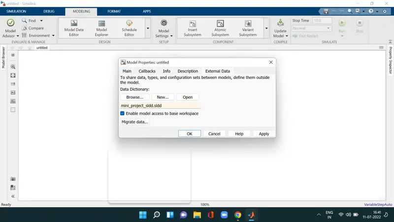
First we create the SLDD file, go to the modeling tab and click on the button which is besides the schedule editor and click on the link to data dictionary then a window will be pop up and create a file and disable the model access to the base workspace and give the inputs to the sldd file
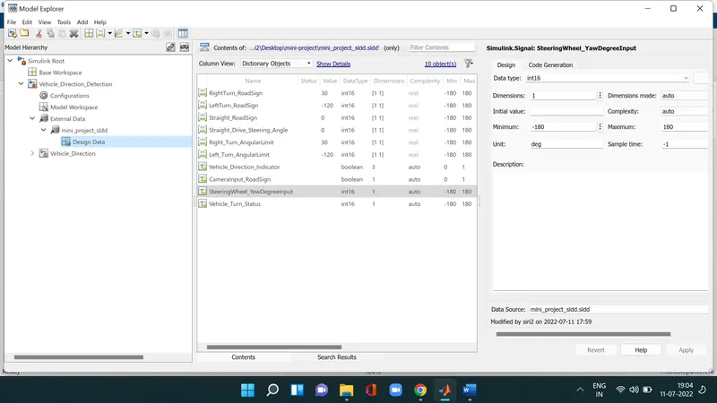
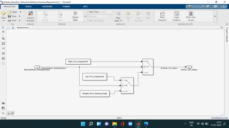
after that we create the requirement_1 subsystem steering wheel input as yawrate is the input for the system here we are used blocks were constants , switches , input and output port then when the angle is greater than 0 then it has to be Right_Turn or if it is not false statement will be coming out to the output and the angle which is equal to zero is staright drive and then the angle is negative it is left turn compare and develop this requirement using switch block

there are two inputs for this subsystem one of its from the output of previous subsystem camerainput_roadsign confirm the occurence of the road sign and these were applied to the relational operator (equal to) and logical AND gate as shown in the sussystem the output of these AND gate are applied to the mux and then through the signal conversion block the output of the subsystem is named as Vehicle direction indicator
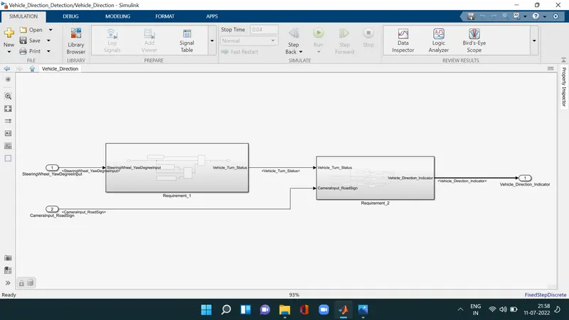
Requirement - 1:
- Steering wheel input as yaw rate (Signal name: SteeringWheel_YawDegreeInput) is the input for this system.
- This is compared against 3 angular values, one each for left turn, right turn & straight drive (Calibration Values: Right_Turn_AngularLimit, Left_Turn_AngularLimit, Straight_Drive_Steering_Angle) to say which specific direction the steering wheel is turning towards.
- Use switch blocks to compare & develop this requirement. Keep this requirement in a subsystem & output of this requirement is a local signal (Signal Name: Vehicle_Turn_Status).
Requirement – 2:
- Keep this requirement as a separate subsystem. Inputs to this requirement are local signal from requirement 1 (Signal Name: Vehicle_Turn_Status) & an input signal from camera (Signal Name: CameraInput_RoadSign), which confirms the occurrence of a road sign.
- Signal Vehicle_Turn_Status is compared against calibration values (Calibration Values: RightTurn_RoadSign, LeftTurn_RoadSign, Straight_RoadSign), if each of them is found equal, then each of the three corresponding output is compared against the camera input signal,
- Using a logical operator block, only one among them is finally given as output signal (Signal Name: Vehicle_Direction_Indicator)
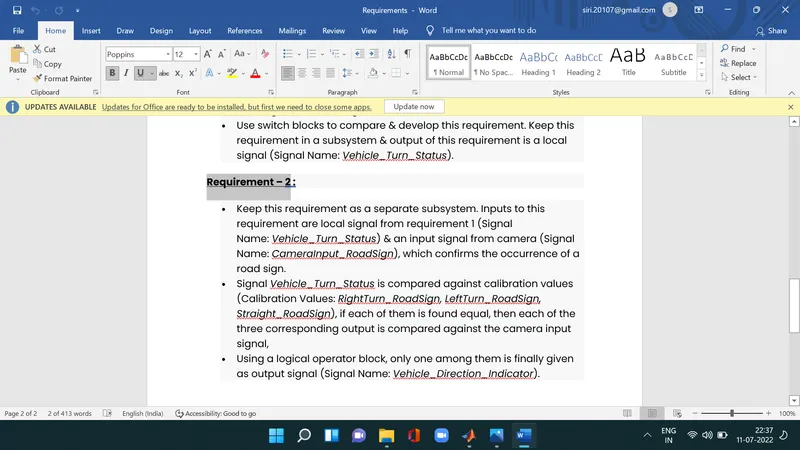
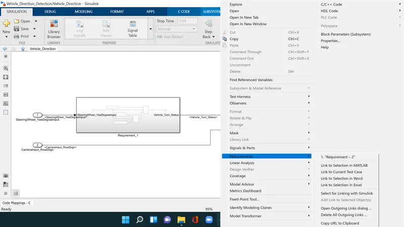
And here we tag the requiremts to the subsystem right click on the subsystem and go to requirements and previously highlight the requirement from word and now link to selection in word
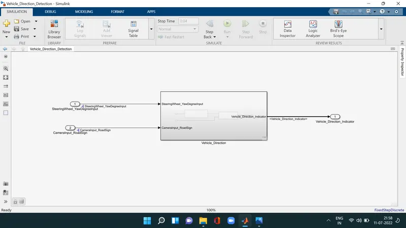
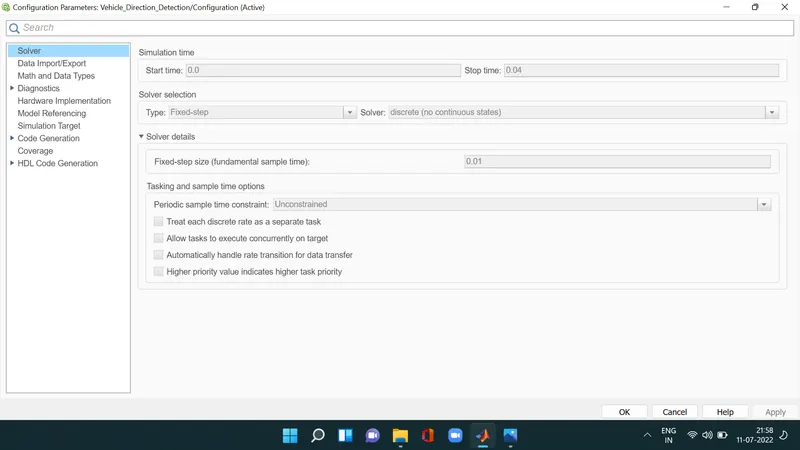
Here we changed the solver settings solver is changed from variable to fixed solver type and solver is selected to discrete (No continuous state) and also sample time is declared as 0.01sec as per the project requirement
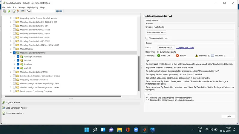
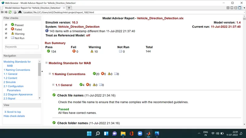
click on the model advisor and go to by tasks and click on MAB Guidelines and click on run selected checks for verification then we get the results here we seen the passed tests ,warnings,fail,notrun and various configuration parameters are updated as per the code generation the solver type should be fix for the code generation and generate the report
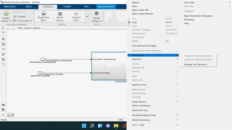
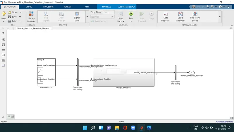
Here we have create the MIL test for the aabove model click on the subsystem and go to testharness and create test harness and input as signal builder and output as outport and click ok then we get the subsystem like the above one
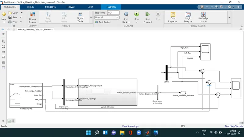
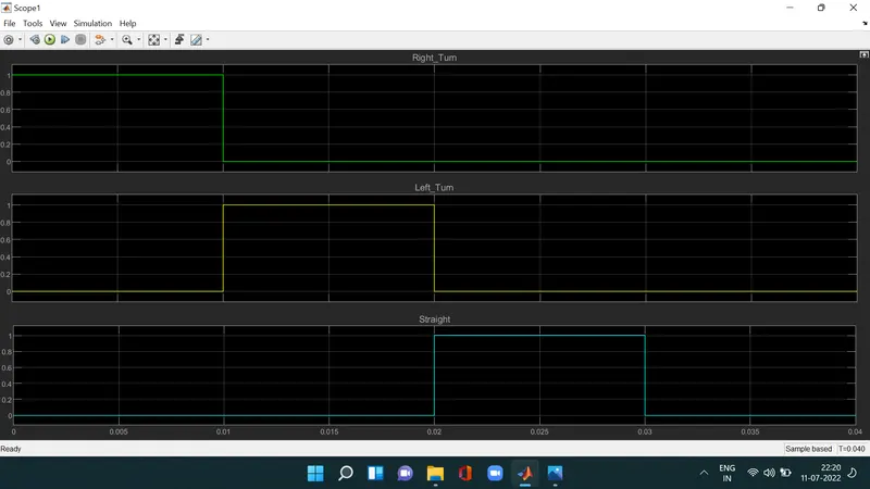
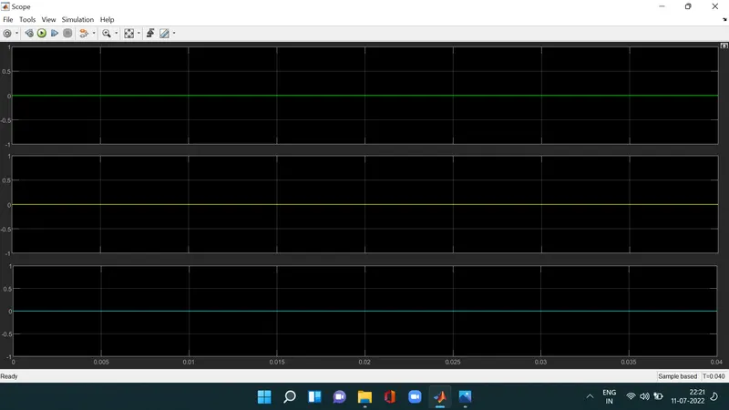
Give the values to signal builder using import from file and using demux take the ouput to scope by using subtract input values from signal builder and output from the port they get cancel each other then the result will be satisfactory
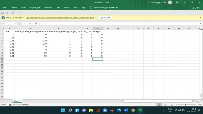
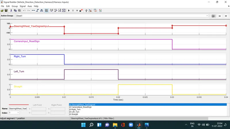
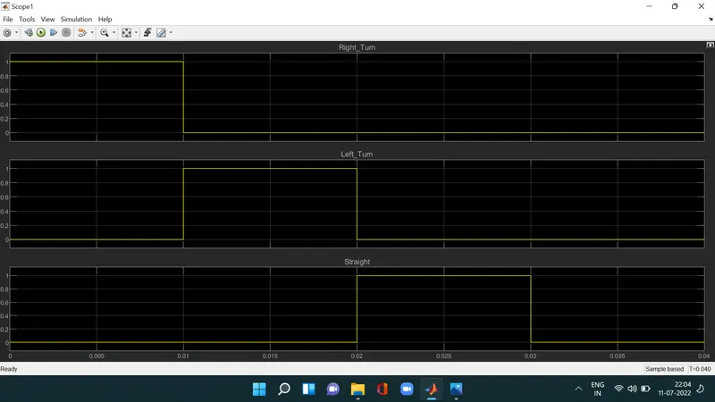
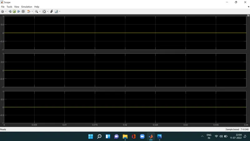
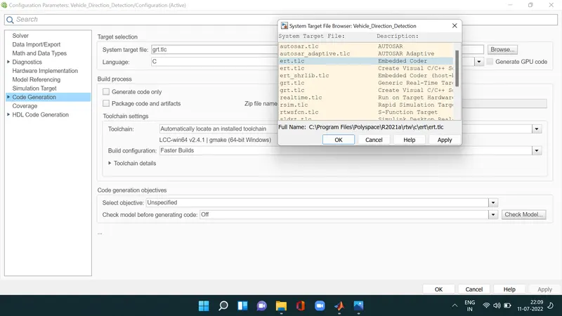
Create the SIL test for the above model first we have go to configuration parameters and under code generation option selecting the embedded coder ert.tlc file as system target file
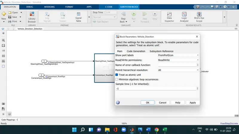
Right click and under the block parameters select the treat as atomic unit
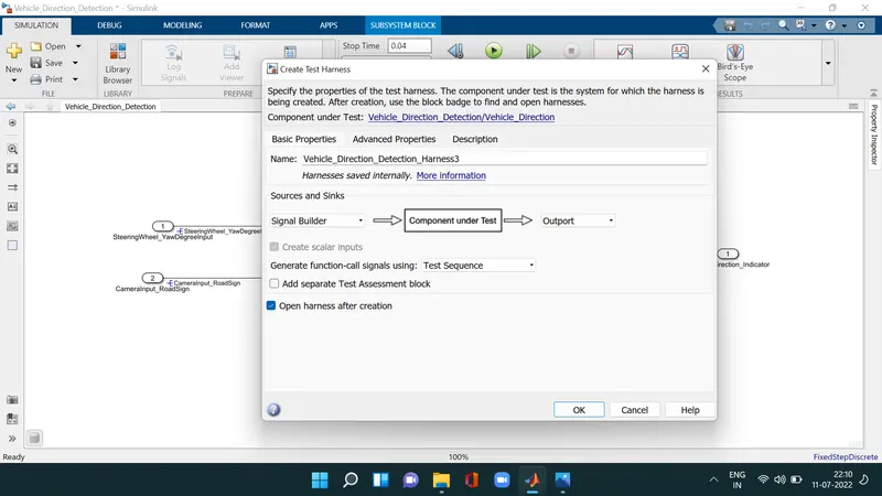
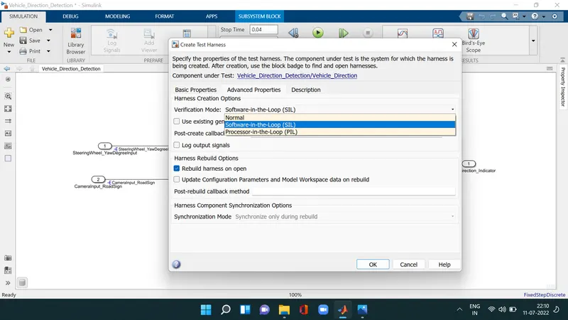
and after that click on the test harness create the testharness for the system select the input as signal builder and output as outport and in advanced properties select the software in loop option and click ok we get the SIL system
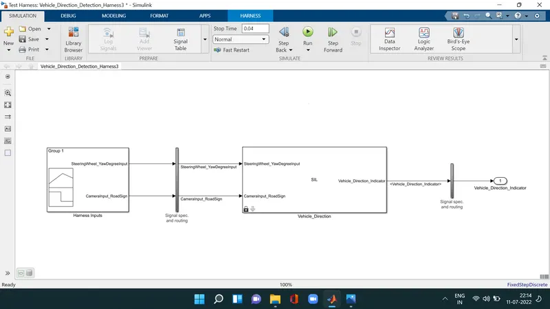
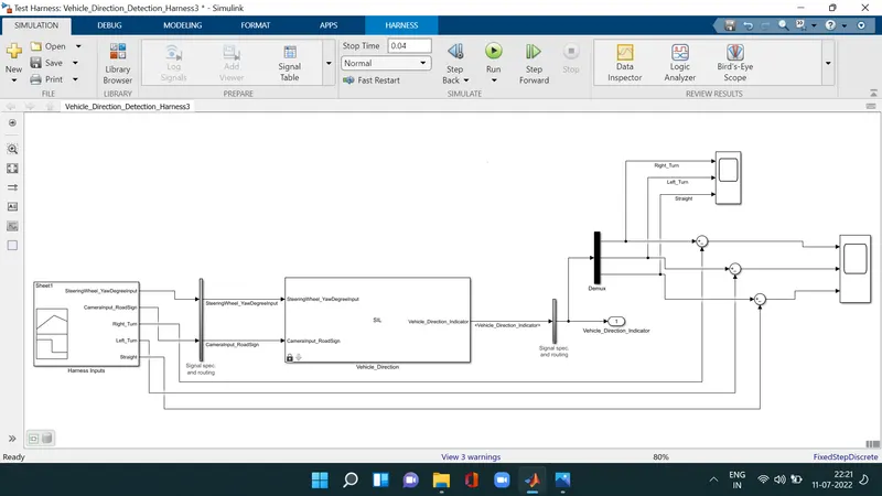
After a new subsystem will pop up like this SIL and double click on the signal builder block and open the file and choose imported from file option and upload the file to signal builder block as input and connect the scope for output and using subtract gievn the connections to the signal builder and output scope then they get cancel each other and our test will be satisfactory
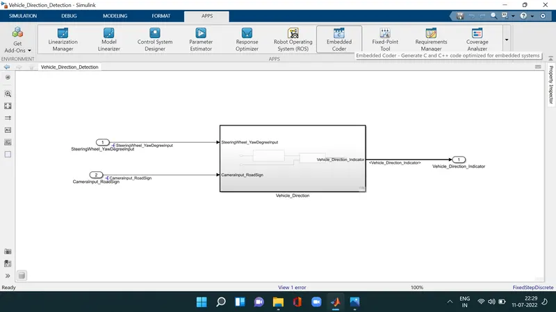
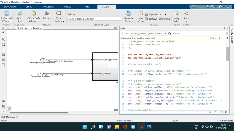
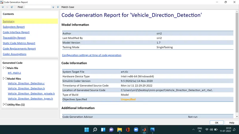
For code generation move to apps tab click on the embedded coder option and build the code then we get the C code for the model
Conclusion : -
the simulink model with the specified subsystems is developed as per the given requirements and created the sldd file as per the signals and calibration list and also we run the model under some tests generate the model advisor report and code generation steps are carried