Project 1 (Mini Project on Vehicle Direction Detection
AIM :
- Development of MATLAB Simulink model as per requirement.
- Tag the requirements to the simulink model; tagging requirement 1 & requirement 2 to their corresponding subsystems is fine.
- MBD compliant changes, Data Dictionary creation & code generation is added advantage, and that is not scope of this project.
- If choosing code generation, Storage class for Input signals: ImportedExtern; Storage class for Output signal: Export to File; Storage class for local signals: localizable; Storage class for calibration signals: Const.
- Choose sample time for all signals as 0.01s
Task:
Making a model of two subsystem according to the requirement.
Requirement - 1:
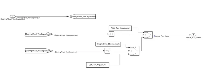
- Steering wheel input as yaw rate (Signal name: SteeringWheel_YawDegreeInput) is the input for this system.
- This is compared against 3 angular values, one each for left turn, right turn & straight drive (Calibration Values: Right_Turn_AngularLimit, Left_Turn_AngularLimit, Straight_Drive_Steering_Angle) to say which specific direction the steering wheel is turning towards.
- Use switch blocks to compare & develop this requirement. Keep this requirement in a subsystem & output of this requirement is a local signal (Signal Name: Vehicle_Turn_Status).
The model for requirement -1
Requirement – 2:
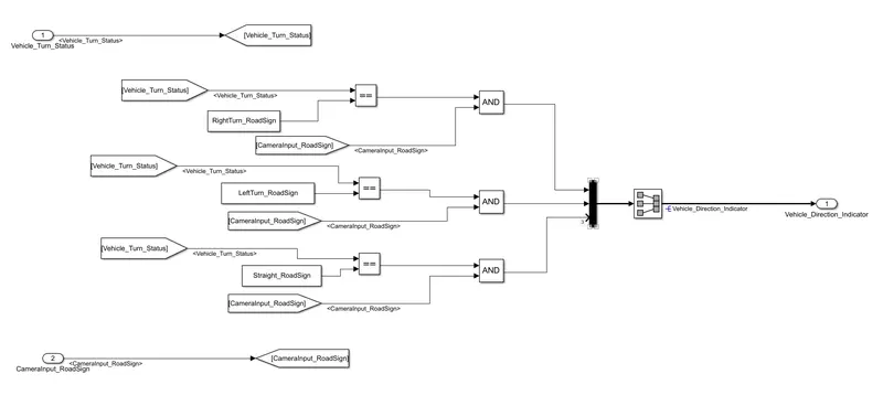
- Keep this requirement as a separate subsystem. Inputs to this requirement are local signal from requirement 1 (Signal Name: Vehicle_Turn_Status) & an input signal from camera (Signal Name: CameraInput_RoadSign), which confirms the occurrence of a road sign.
- Signal Vehicle_Turn_Status is compared against calibration values (Calibration Values: RightTurn_RoadSign, LeftTurn_RoadSign, Straight_RoadSign), if each of them is found equal, then each of the three corresponding output is compared against the camera input signal,
- Using a logical operator block, only one among them is finally given as output signal (Signal Name: Vehicle_Direction_Indicator).
The model for requirement-2
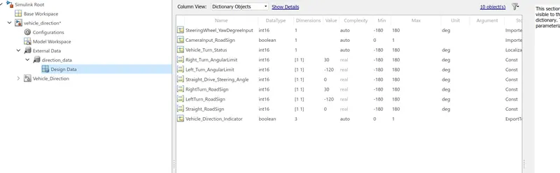
The signals are resolved at their source and propogated further in areas where they are used.
SLDD file is created according to the given specification
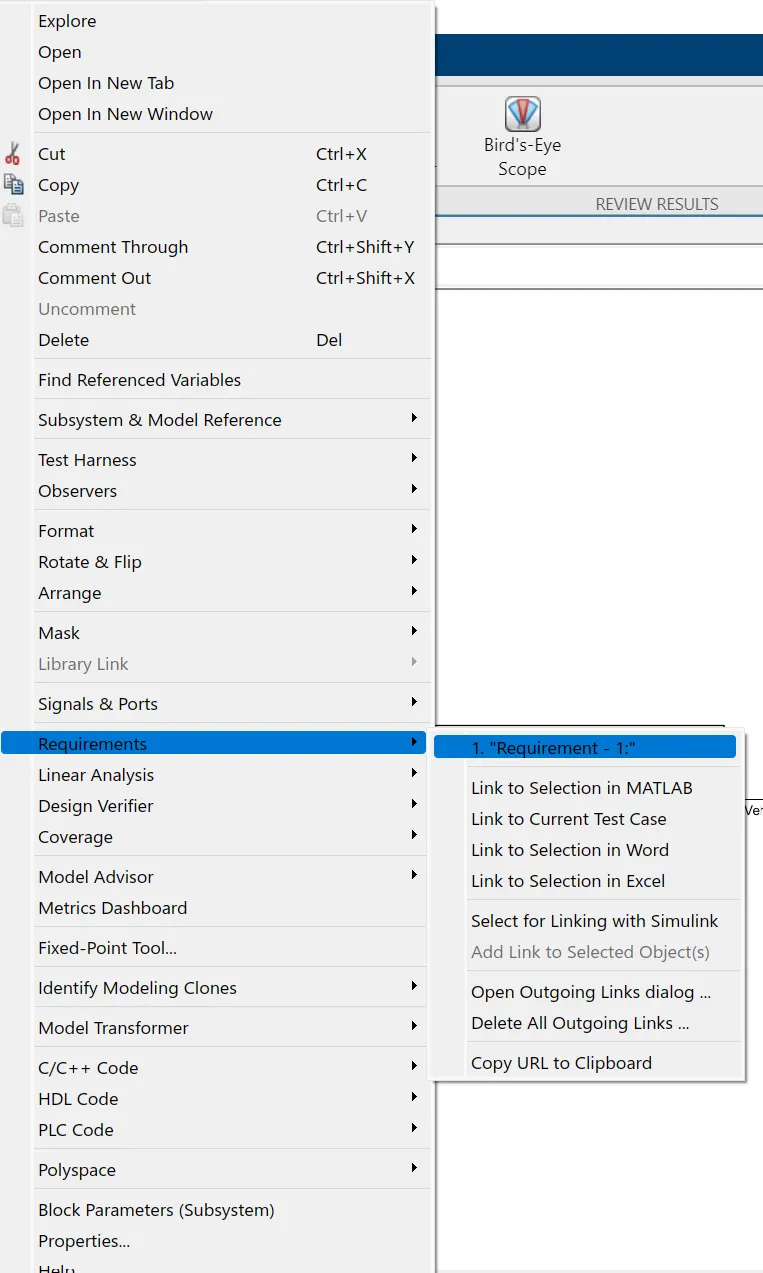
Requirement tagging is done by highlighting the requirement headlines. Then right click on the corresponding subsystem and then click on the requirements and then select link to selection in word.
Next, Model advisor check is done. For that first we have to change the solver configuration. For that following steps are done
Modellin>Model settings. Then change the solver and code generation settings.
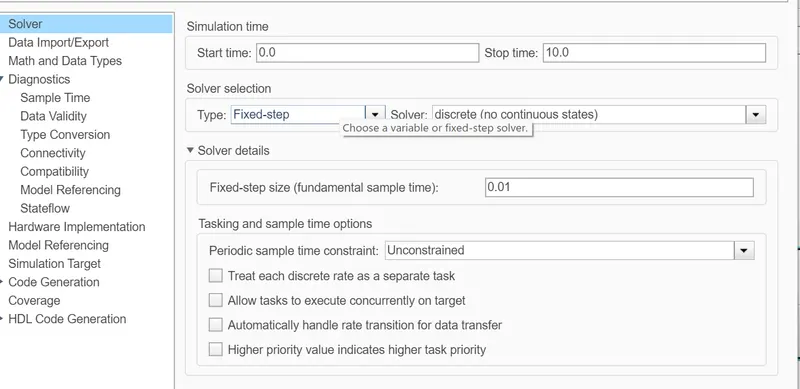
Solver, here solver type is changed to fixed and discrete. Then sample time is changed to 0.01sec.
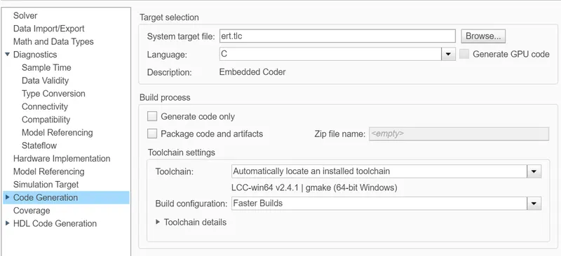
Code generation, Here system target file is changed to embedded coder.
Then model advisor check function is done.
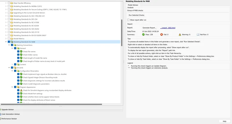
The errors are reduced and ensured that there are no fail checks.
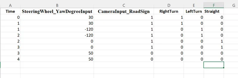
Excel file is created for entering the test cases for MIL and SIL tests.
For MIL test, Test harness is created first.
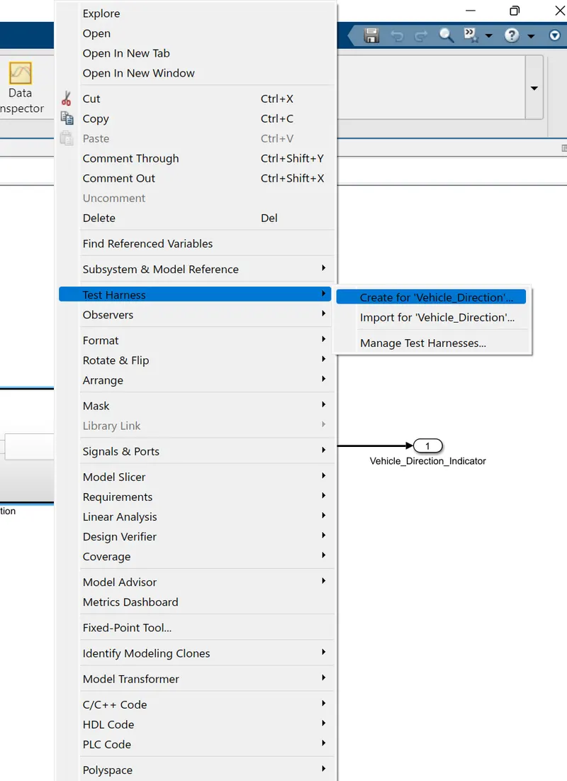
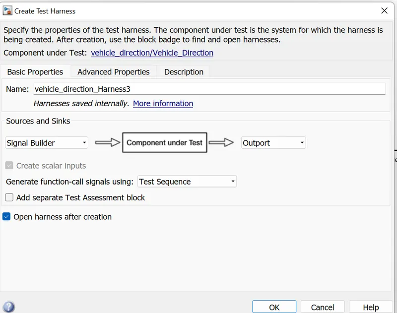
Here signal builder is selected as input and verification model is chosen as normal for MIL test.
The test cases are imported to the signal builder from the excel sheet.
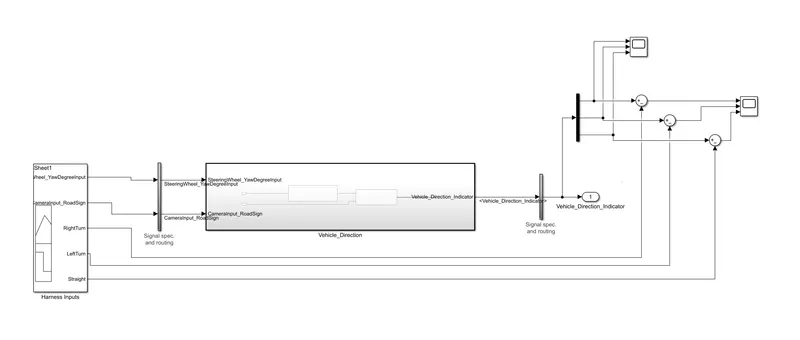
DeMux is used to obtain the three ouptuts. These outputs are sompared with the inputs from signal builder
Input waveform from the signal builder is
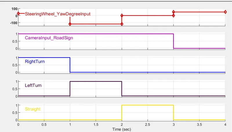
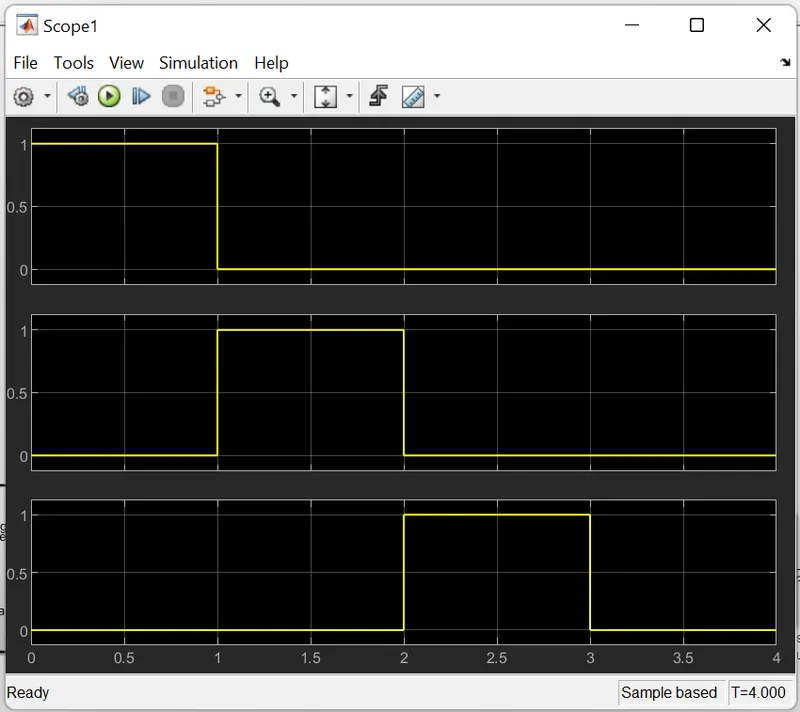
For 0 to 1 sec the direction will be towards right and from 1 to 2sec the direction will be towards left and from 2 to 3 sec the direction will be straight.
When camera input is zero whatever be the other inputs the output will be zero.
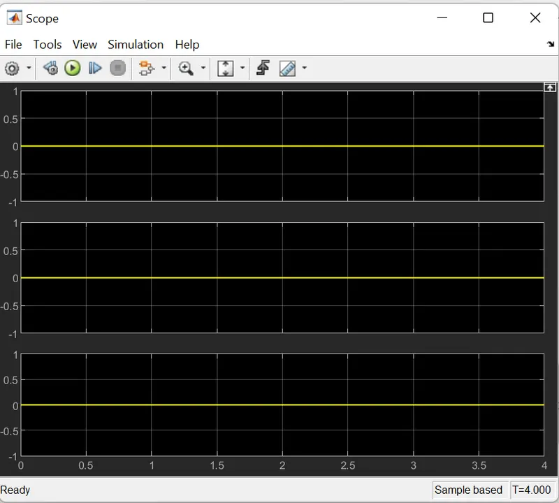
The output after taking the difference between input and output is shown above.
It is evident from the above graph that the model follows the input commands and this resulted in their difference being zero.
In order to do SIL test again test harness is created by following the same procedure. But before that the vehicle direction subsystem has to be converted to atomic subsystem.
For that right click the subsystem and then in block parameters check the Treat as atomic unit.
Follow similar procedures accept that while creating test harness change the verification mode to Software-in-the-Loop(SIL)
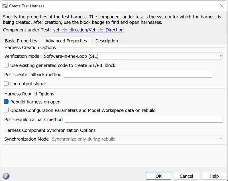
C-code will be formed in the same folder
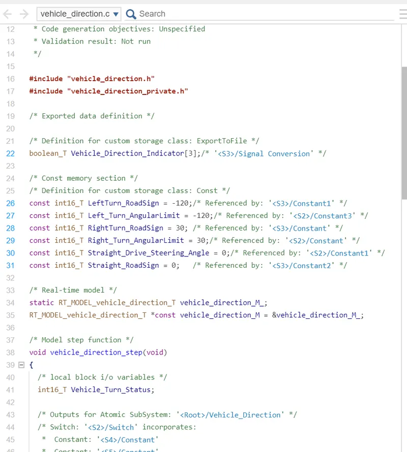
The model developed is
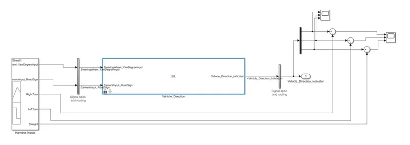
Demux is connected and output obtained is
The difference between input and output is given below
CONCLUSION
Matlab model has been developed as per the requirements.
SLDD file is created for signals and constants.
Model advisor checks is done and the report is obtained.
Model In Loop testing and Software In Loop testing is done.
The output waveform generated is compared in both the testing.