Project 1 (Mini Project on Vehicle Direction Detection
Aim:
To detemine the vehicle direction etermination of a vehicle using matlab
Mini Project - Vehicle Direction Determination
General Overview:
- Identifying the direction of the vehicle is one of the important & diverse features in Autonomous driving & Advanced Driver Assistance Features.
- This particular sub-feature of identifying the direction of vehicle is basically identifying the direction the vehicle is taking based on the camera input.
- Camera reads the road signs & stores into its memory with unique values for left turn, right turn & straight drive.
- Depending on the direction it is taking, final indication is given to the driver – as an indication if he is driving in the recommended direction or not.
- Vehicle Direction Determination can also be coupled along - side features like GPS systems to identify whether the vehicle is reaching its destination in an optimized manner.
- This sub feature can also be used along with Lane Detection, Highway Warning, Ramp Entry / Exit in Wrong Way Detection etc.
Objective of Mini Project:
- Development of MATLAB Simulink model as per requirement.
- Tag the requirements to the simulink model; tagging requirement 1 & requirement 2 to their corresponding subsystems is fine.
- MBD compliant changes, Data Dictionary creation & code generation is added advantage, and that is not scope of this project.
- If choosing code generation, Storage class for Input signals: ImportedExtern; Storage class for Output signal: Export to File; Storage class for local signals: localizable; Storage class for calibration signals: Const.
- Choose sample time for all signals as 0.01s
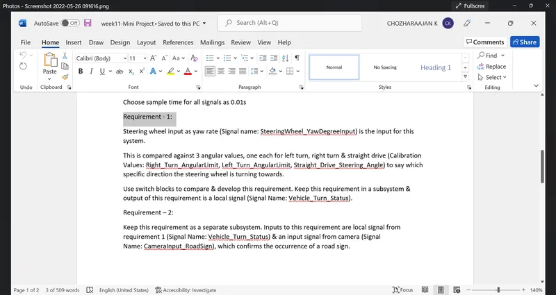
Requirement - 1:
- Steering wheel input as yaw rate (Signal name: SteeringWheel_YawDegreeInput) is the input for this system.
- This is compared against 3 angular values, one each for left turn, right turn & straight drive (Calibration Values: Right_Turn_AngularLimit, Left_Turn_AngularLimit, Straight_Drive_Steering_Angle) to say which specific direction the steering wheel is turning towards.
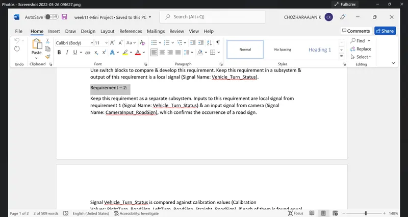
- Use switch blocks to compare & develop this requirement. Keep this requirement in a subsystem & output of this requirement is a local signal (Signal Name: Vehicle_Turn_Status).
Requirement – 2:
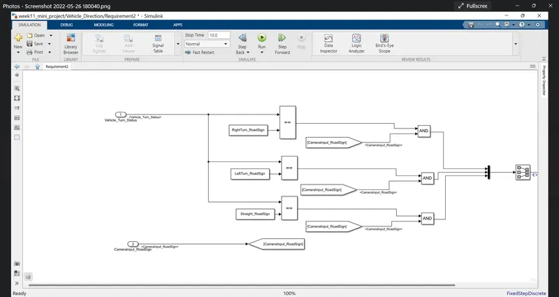
- Keep this requirement as a separate subsystem. Inputs to this requirement are local signal from requirement 1 (Signal Name: Vehicle_Turn_Status) & an input signal from camera (Signal Name: CameraInput_RoadSign), which confirms the occurrence of a road sign.
- Signal Vehicle_Turn_Status is compared against calibration values (Calibration Values: RightTurn_RoadSign, LeftTurn_RoadSign, Straight_RoadSign), if each of them is found equal, then each of the three corresponding output is compared against the camera input signal,
- Using a logical operator block, only one among them is finally given as output signal (Signal Name: Vehicle_Direction_Indicator).
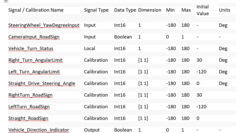
Signals & Calibration Data List:
|
Signal / Calibration Name |
Signal Type |
Data Type |
Dimension |
Min |
Max |
Initial Value |
Units |
|
SteeringWheel_YawDegreeInput |
Input |
Int16 |
1 |
-180 |
180 |
- |
Deg |
|
CameraInput_RoadSign |
Input |
Boolean |
1 |
0 |
1 |
- |
- |
|
Vehicle_Turn_Status |
Local |
Int16 |
1 |
-180 |
180 |
- |
Deg |
|
Right_Turn_AngularLimit |
Calibration |
Int16 |
[1 1] |
-180 |
180 |
30 |
Deg |
|
Left_Turn_AngularLimit |
Calibration |
Int16 |
[1 1] |
-180 |
180 |
-120 |
Deg |
|
Straight_Drive_Steering_Angle |
Calibration |
Int16 |
[1 1] |
-180 |
180 |
0 |
Deg |
|
RightTurn_RoadSign |
Calibration |
Int16 |
[1 1] |
-180 |
180 |
30 |
|
|
LeftTurn_RoadSign |
Calibration |
Int16 |
[1 1] |
-180 |
180 |
-120 |
|
|
Straight_RoadSign |
Calibration |
Int16 |
[1 1] |
-180 |
180 |
0 |
|
|
Vehicle_Direction_Indicator |
Output |
Boolean |
1 |
0 |
1 |
- |
- |
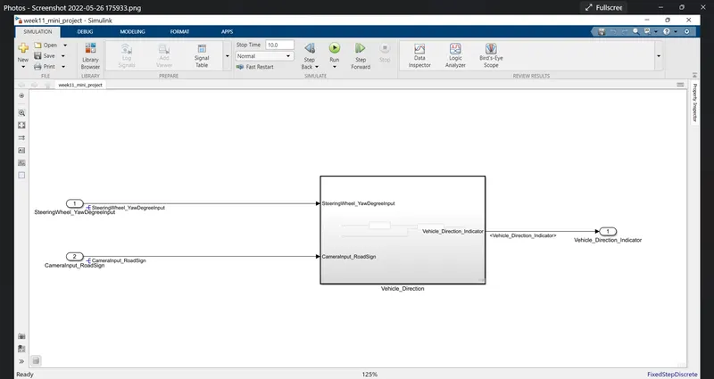
- Create the required subsystem with the name "Vehicle_direction"
- inside the subsystem create two subsystem namely requirement1 and requirement2
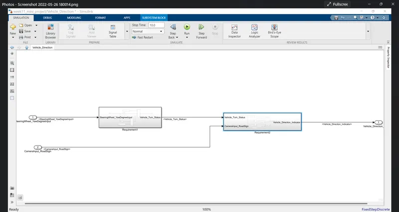
- The two requirements are used here as per the requirement document
- the vehicle direction detection is the mini project where we use advanced features like autonomous driving and advanced driver assistance features
- the main safety feature is that all the partial autonomous cars have these tests
- the added advantage of this ADAS is when the emergency condition this function helps out a lot
- It also have an camera input ehich detects the raod signs like left turn, right turn, about turn, speed limit, slope, no horn zone etc like that
- with the help of this input we can compare it with the functions like ADAS and compare the system
- the camera assistance indicates the direction in which the car has to go in left turn or right turn or straight drive direction
- this is essential input which confirms the given signal in ECU unit
- This feature is mandatory in the fully automatic cars like tesla to detect the lane changing, front and back vehicle detect collision system
- The main subsystem is named as Vehicle_Direction which has the Steering angle saw input degree
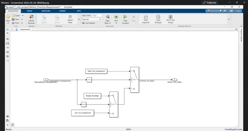
- the vehicle direction depends directly on the steeering angle of the vehicle
- there are some given input signal and along with the range and values needed to enteredf in the matlab model explorer.
- the two inputs are steering angle and camera input and output of the system is vehicle direction
- the subsystem is further is classified into two system with requirement1 and requirement2
- all the requirement 1 and requirement 2 in the given word files are connected as per the requirement given
- The steering angle and camera input is given as input and output as vehicle direction
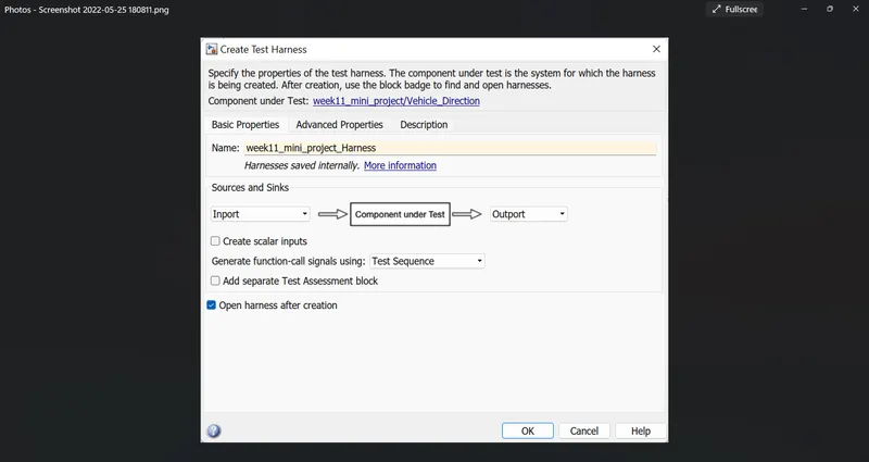
- in requirement1 has switch blocks is used which have used to check the conditions with the vehicle right turn,left turn and straight drive
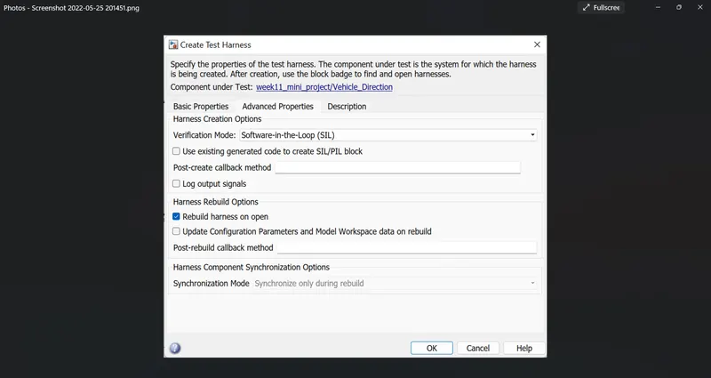
- another switch is created with the false condition is given to camera input
- the output of this switch is given to requirement2
- the vehicle turn status is given as input to the relational operators and compared against right turn ,left turn and straight drive
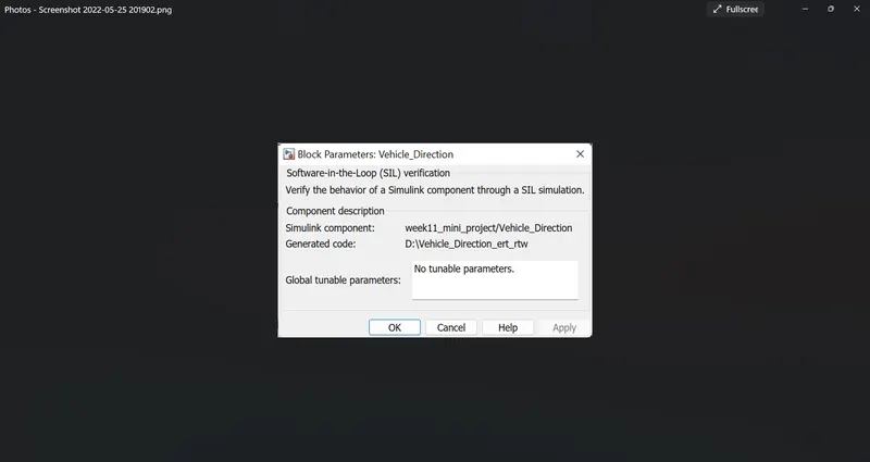
- the output of the comparator is given to the and gate and output is given to vehicle direction output
- the and gate has two inputs one is connected right turn and other one is camera is input
- the all outputs are connected to the mux block which handles the same data type input and gives single output
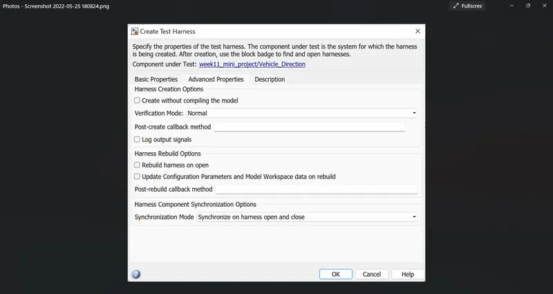
- again the mux is connected to the signal conversion
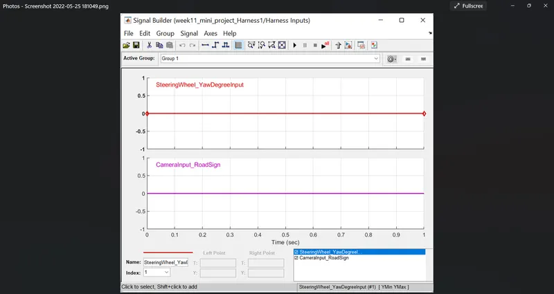
- all the signals and constant values are assigned in the simulink data dictionary file
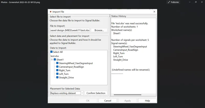
- from the SLDD file all the values are assigned
- we need to propogate and resolve the signals
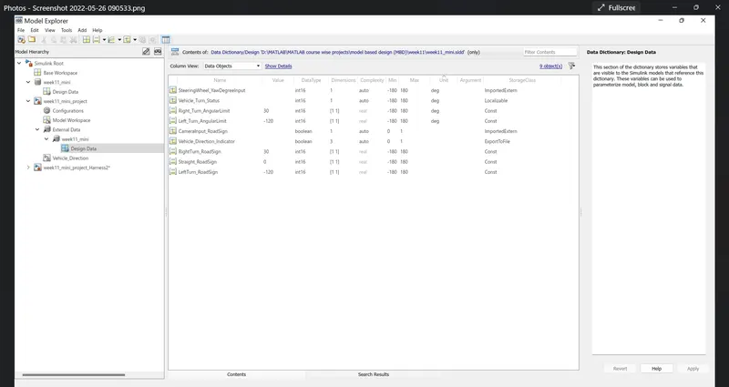
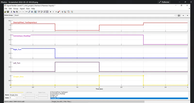
- resolving a signal is from the the sldd files
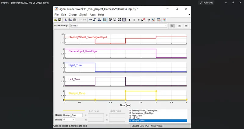
- then we have create a MIL model in loop test and generate those results
- then sil software in loop is created for the files and the codes are generated
- in SIL the coe shoukd be genearted
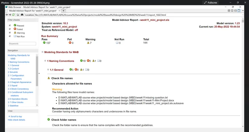
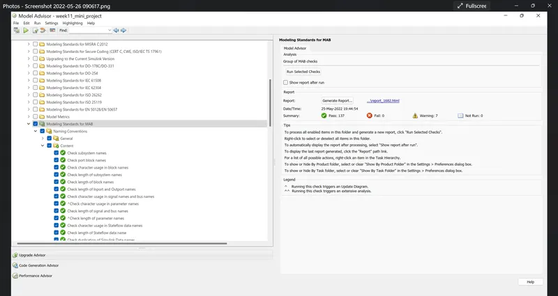
- model aadvisor is to be run for the given programs
- it has 144 checks and there should not be any fail conditions
- model advisor check is only for mab methods only
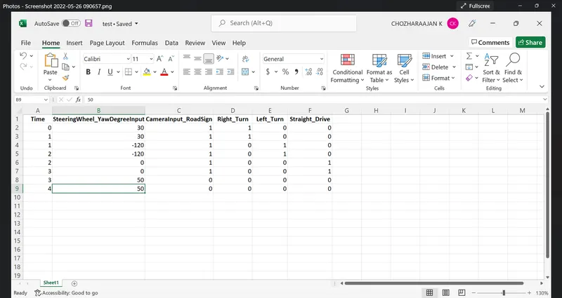
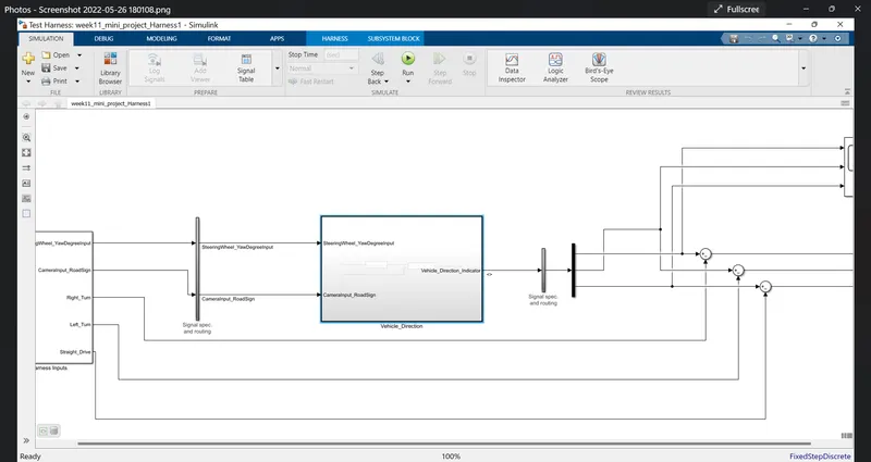
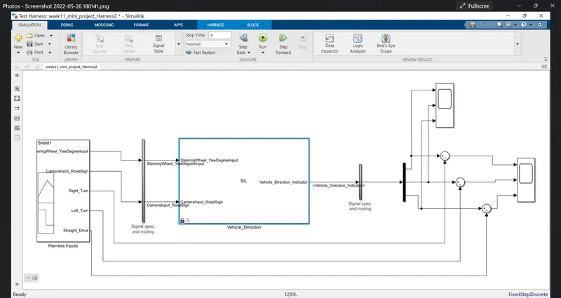
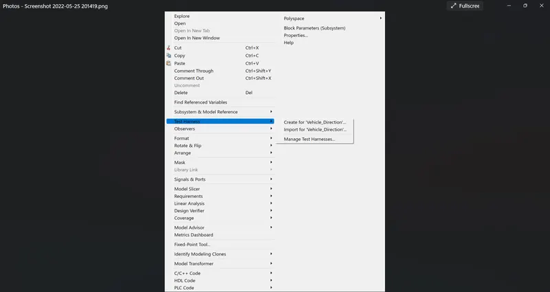
- the test harness should be have the scope and a signal buikder is assigned
- signal builder the test case files are uploaded in it
- the model is set as atomic unit
- the model setting the solver configuration is used as fixed step and the 0.01 as sample time
- the code is set as grt.c file
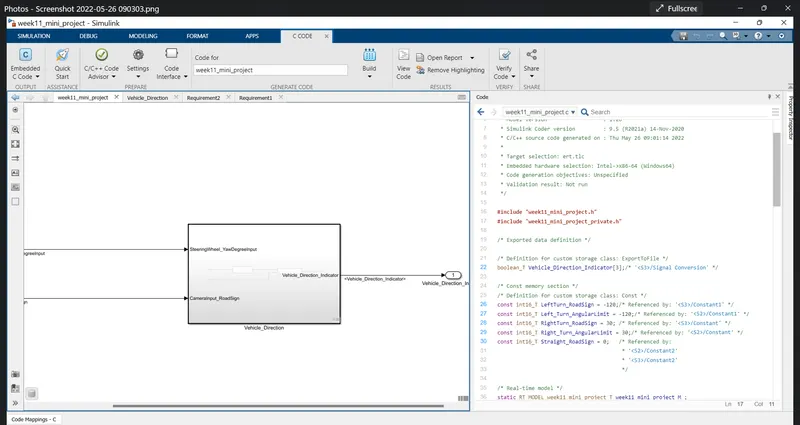
- all the values are explained
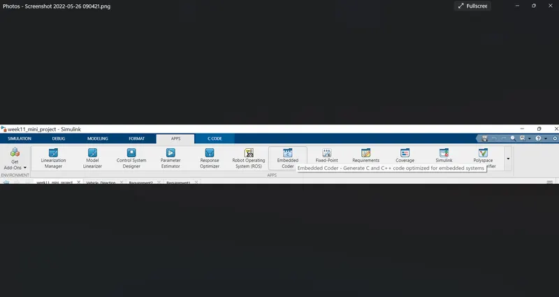
- the final code is generated using the embedded coder
- the code is given below
Conclusion:
All the given conditions is done for the above mini project