Project 1 (Mini Project on Vehicle Direction Detection
Vehicle Direction:-
Vehicle direction and road sign is absorve the vehicle movement.
Create a Subsystem input as a Steeringwheel_YawDegreeInput and CameraInput_RoadSign and Output is aVehicle_Direction_Indicator is connected.SubSystem name is Vehicle_Direction. Signals resolve and ProPagted is used for signals.
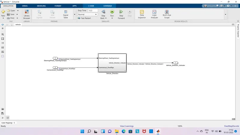
Sub System:-
Subsystem is inner subsystem is created Requirement 1 and 2 Requirement 1 is SteeringWheel_YawDegreeInput and Output is Vehicle_Turn_Status this status is connected Requirement 2 Input and another input is CameraInput_RoadSign this requirement 2 output is Vehicle_Direction_Indicator.
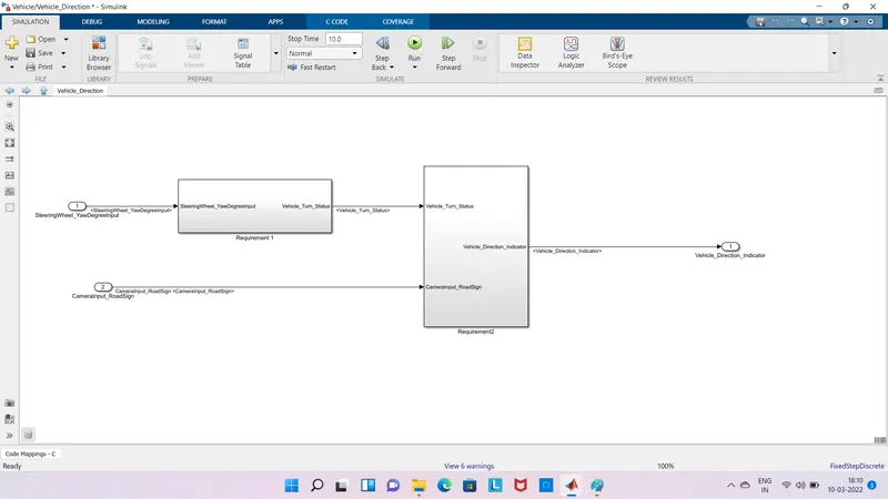
Requrement1:-
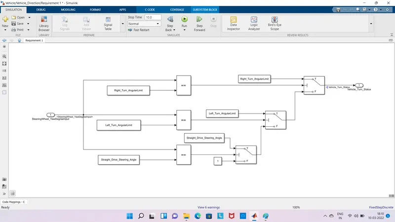
Requirement 1 is SteeringWheel_YawDegreeInput is a input is '==' Operator and this operator another input is AngularLimit(Right,Left,Straight Drive) this operator is connected to switch this output is Vehicle Turn Status
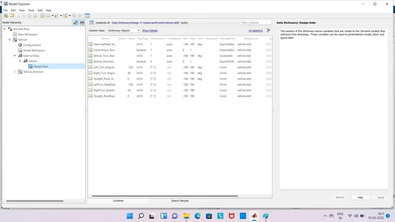
Requirement 1 is operated IF Else method and angular limit right and left some limit value is input this value is stored in model workspace.Equal operator is value checked is both values are equal condition true its go to the output if false checked another condition.
Requirement2:-
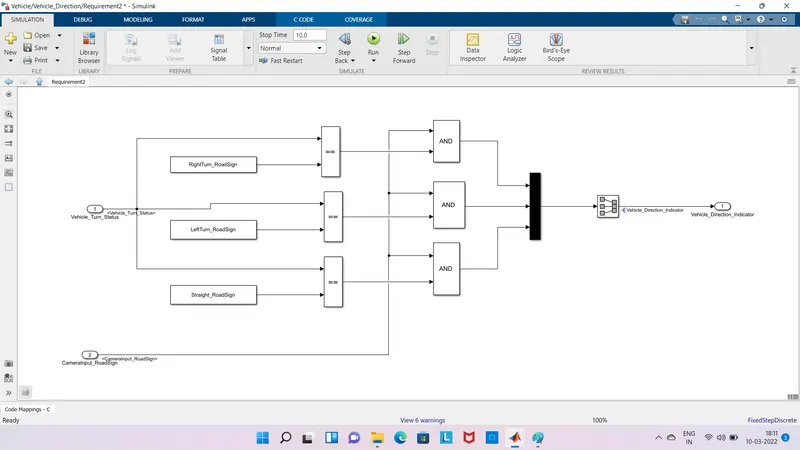
Requirment 1 output is connected to the Requirement 2 this is Vehicle turn status and Road sign(Left,Right,Straight){stored the value in work space} is input to the Equal operator so this condition is true output goes to the AND Operator this operator is another input as a camera road sign its checked the road sign,three signals are connect to the Multiplex operator this goes to the signal output its comes the three output so convert the signal conversion is used signal is change from output.
ModelWorkSpace:-
Road sign,angular limit and turn status,Direction indicator (Vehicle Direction indicator is output is three output so change the Datatype Value is 3) is values is stored from the work space.
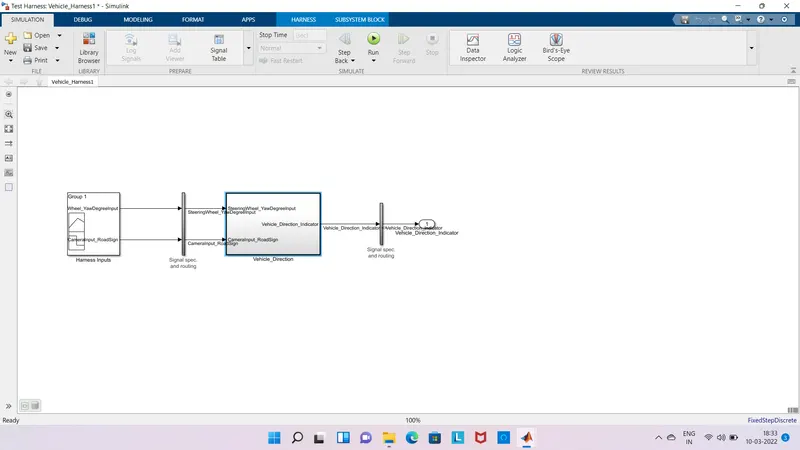
Create a Test Harness for MIL:-
Create a MIL from test Harness in MIL Input is changed the Signal Builder to create MIL.
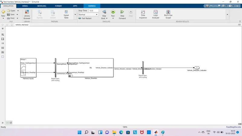
Create aTest Hareness for SIL:-
First a block is creat a Atomic unit and then created a test harness for SIL Input as aSignal Builder to create the signal builder to create the Code Genrate.
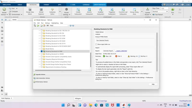
Model Advisor Report:-
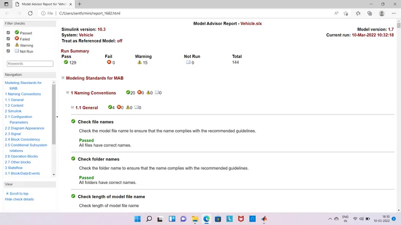
Modeling tab is check the Model for Modeling Standrards for MAB is selected its seleted the checks Pass is cecked ok Fail is must be Zero Warnings is maximum is 15 if fail zero generate report.
C Code:-
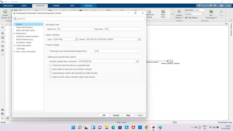
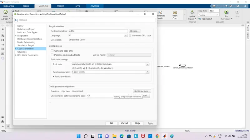
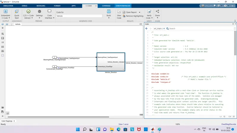
Code is creatror from configuartion Parameter is solver is type fixed type and solver isdiscrtete sample time is 0.01 and select code generation is system target file is selectedis ert.tlc is embeddedcoder so build the code is created embedded code.
OutPut:-
Finally get the OutPut for Generated for Model Advisor report and embedded code.