Project 1 (Mini Project on Vehicle Direction Detection
Vehicle Direction Determination
Objective of Mini Project:
- Development of MATLAB Simulink model as per requirement.
- Tag the requirements to the simulink model; tagging requirement 1 & requirement 2 to their corresponding subsystems is fine.
- MBD compliant changes, Data Dictionary creation & code generation is added advantage, and that is not scope of this project.
- If choosing code generation, Storage class for Input signals: ImportedExtern; Storage class for Output signal: Export to File; Storage class for local signals: localizable; Storage class for calibration signals: Const.
- Choose sample time for all signals as 0.01s
Signals & Calibration Data List:
|
Signal / Calibration Name |
Signal Type |
Data Type |
Dimension |
Min |
Max |
Initial Value |
Units |
|
SteeringWheel_YawDegreeInput |
Input |
Int16 |
1 |
-180 |
180 |
- |
Deg |
|
CameraInput_RoadSign |
Input |
Boolean |
1 |
0 |
1 |
- |
- |
|
Vehicle_Turn_Status |
Local |
Int16 |
1 |
-180 |
180 |
- |
Deg |
|
Right_Turn_AngularLimit |
Calibration |
Int16 |
[1 1] |
-180 |
180 |
30 |
Deg |
|
Left_Turn_AngularLimit |
Calibration |
Int16 |
[1 1] |
-180 |
180 |
-120 |
Deg |
|
Straight_Drive_Steering_Angle |
Calibration |
Int16 |
[1 1] |
-180 |
180 |
0 |
Deg |
|
RightTurn_RoadSign |
Calibration |
Int16 |
[1 1] |
-180 |
180 |
30 |
|
|
LeftTurn_RoadSign |
Calibration |
Int16 |
[1 1] |
-180 |
180 |
-120 |
|
|
Straight_RoadSign |
Calibration |
Int16 |
[1 1] |
-180 |
180 |
0 |
|
|
Vehicle_Direction_Indicator |
Output |
Boolean |
1 |
0 |
1 |
- |
- |
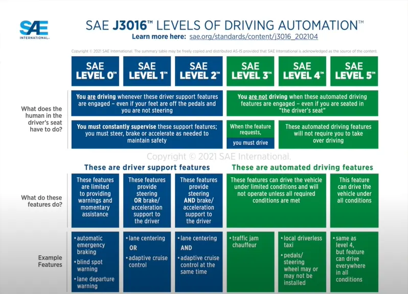
- Here's are the level of Autonomous driving from 0 to 5 as per the SAE.
- SAE full form is Society for Automotive Engineeers.
- All the automotive company, OEMs are follow the guidlines of SAE.
- so, they decided the 6 level of autonomous from 0 to 5.
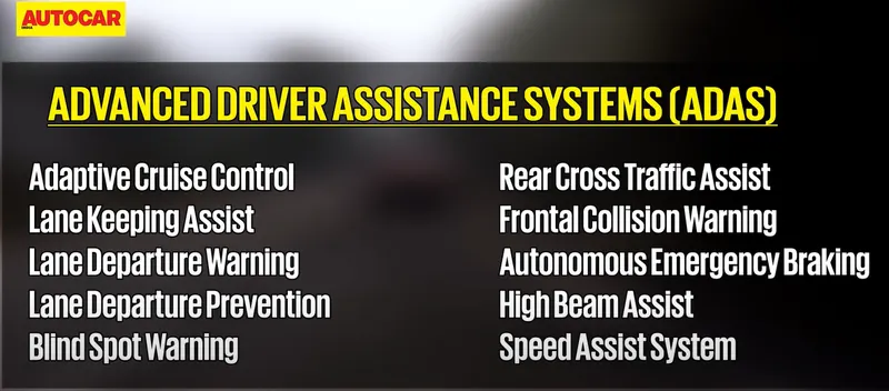
- In ADAS we have many no. of function around 20+ today.
- in future it will increasing much more.
- here's are the some features of ADAS.
- In this project we are working on Vehicle direction detction feature of ADAS.
- Identifying the direction of the vehicle is one of the important & diverse features in Autonomous driving & Advanced Driver Assistance Features. This particular sub-feature of identifying the direction of vehicle is basically identifying the direction the vehicle is taking based on the camera input.
- Camera reads the road signs & stores into its memory with unique values for left turn, right turn & straight drive. Depending on the direction it is taking, final indication is given to the driver – as an indication if he is driving in the recommended direction or not.
- Vehicle Direction Determination can also be coupled along - side features like GPS systems to identify whether the vehicle is reaching its destination in an optimized manner. This sub feature can also be used along with Lane Detection, Highway Warning, Ramp Entry / Exit in Wrong Way Detection etc.
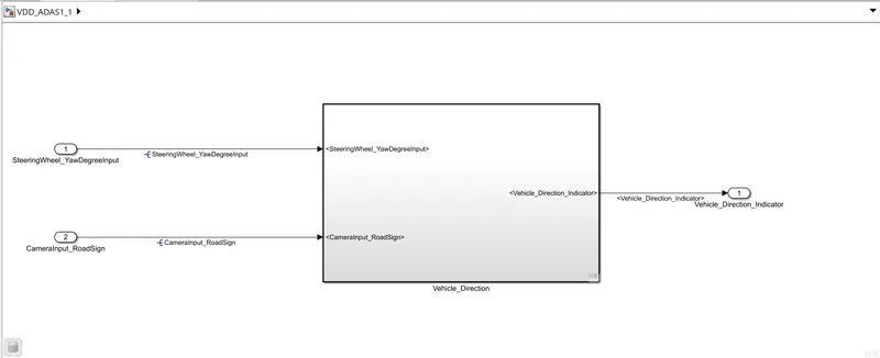
MAIN MODEL :
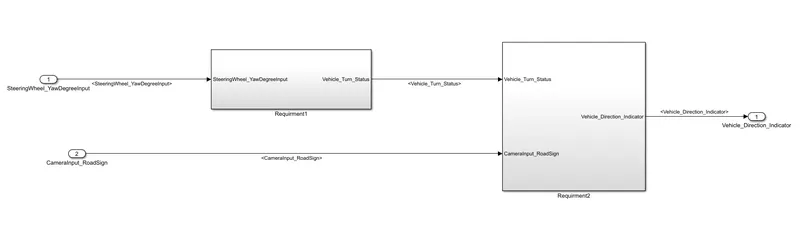
SUBSYSTEMs:
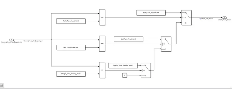
Requirement - 1:
- In the 'requirment 1' subsystem, the Steering wheel input as yaw rate (Signal name: SteeringWheel_YawDegreeInput) is the input for this system.
- This value is compared against 3 angular values, one each for left turn, right turn & straight drive (Calibration Values: Right_Turn_AngularLimit, Left_Turn_AngularLimit, Straight_Drive_Steering_Angle) to say which specific direction the steering wheel is turning towards by using '==' relational operator and Switch block.
- '==' block will give logic 1 or 0 if both are matching or not and then send the signal to switch block.
- Switch block will work as if else statement after receiving value from relational operator.
- if non of the condition is statisfied it will give zero in outport of 'Vehicle_Turn_Status'.
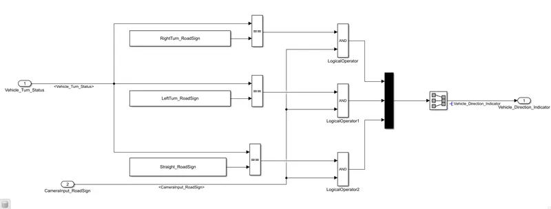
Requirement – 2:
- Inputs to this requirement are local signal from requirement 1 (Signal Name: Vehicle_Turn_Status) & an input signal from camera (Signal Name: CameraInput_RoadSign), which confirms the occurrence of a road sign.
- Signal Vehicle_Turn_Status is compared against calibration values (Calibration Values: RightTurn_RoadSign, LeftTurn_RoadSign, Straight_RoadSign) by using 'relational operator block' if each of them is found equal, then each of the three corresponding output is compared against the camera input.
- Using a logical operator block, only one among them is finally given as output signal (Signal Name: Vehicle_Direction_Indicator).
- The boolean output signal obtained from each of the three 'And' blocks are fed to the Outport 'Vehicle_Direction_Indicator' will be a three dimension signal having three boolean elements, that's why we are using 'Mux' and 'Signal Conversion' Block.
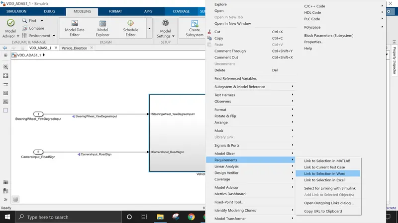
Requirment Tagging :
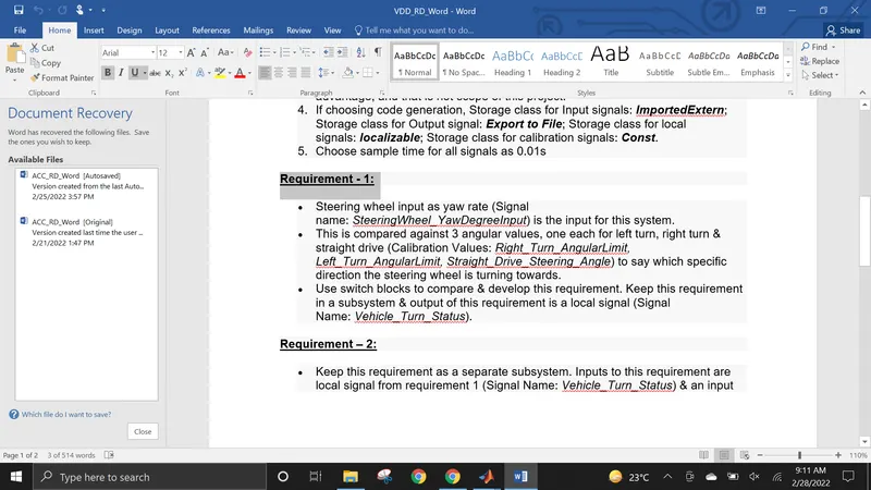
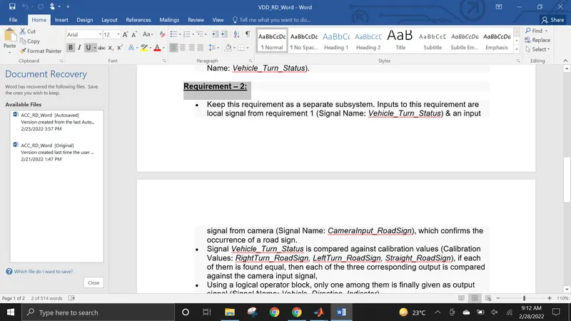
- In word document we have already requirment in form of word.
- so we need to highlight first our requirment.
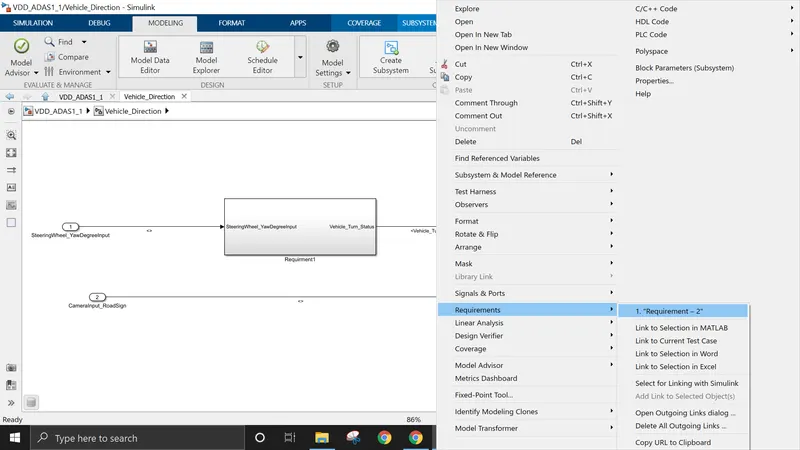
- then in Simulink after right clicking go to requirment and then link to selection in word
- then again go to requirments where we can see our hifghlighted text.
- click on it so finally requirment tagging is done.
- Same, in this case aswell.
- instead of choosing requirment 1 in word we have to choose requirment 2.
- then follow the same process as before.
Creation Of Simulink Data Dictionary File (SLDD) :
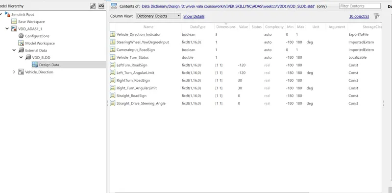
- A SLDD file is created which contain the input, output signals and calibration parameters used in the model.
- for creating SLDD file first click on Modeling then link to data dictionary
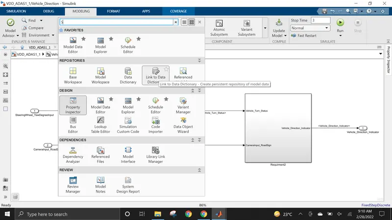
- then click on NEW and browse the location where we need to add the file.
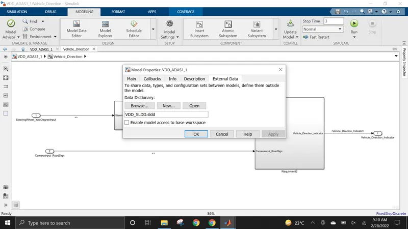
- we need to remove the access to base workspace.
- then we can add data,parameters,Signal, etc.. what we want into it by going to model explorer.
Model Configuration Settings:
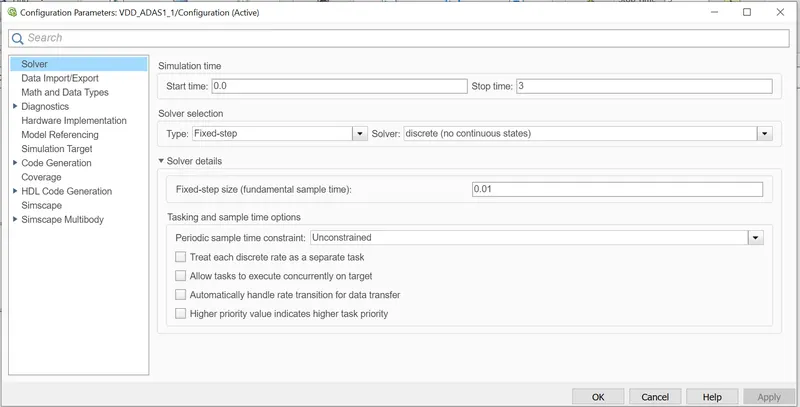
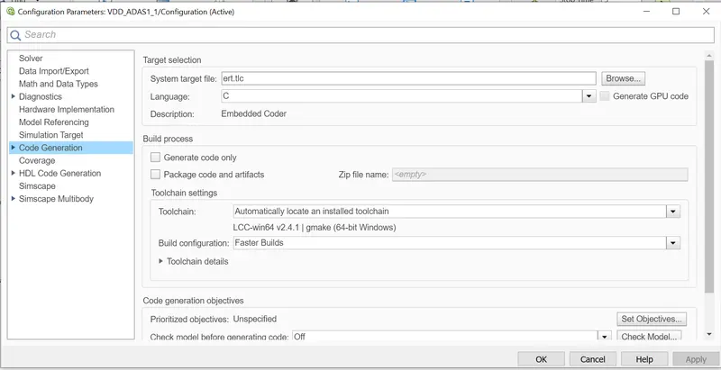
- For checking the model advisor or MAAB guidelines first we need to set the parameters.
- we can set it in model settings.
- set solver value, set code generation as show in below figure then click apply or ok.
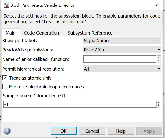
- For, SIL testing we need to enable treat as Atomic unit.
MAAB Guidelines check in Model Advisor :
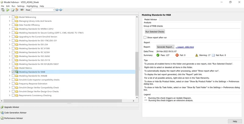
- This check is performed using "model advisor" tools to see whether the developed model meets the modeling standards for MAAB.
- to check this open that simulink model do model settings then go to model then click on model advisor.
- where we have diff option which subsystem or main model which you want to check.
- then wehave option like for which standards you need to do model advisor like for simulink, for matlab, for signals as you can see in below figure.
- here we are checking Modeling standards for MAB by clicking on that and then click on Run Selected Checks.
- so, after it will automatically processing the output and after clicking on generate report it will generate the report aswell.
- here we have 0 fail so our model is working fine but 17 warnings.
- we can reduce no. of error and warning by clicking on that perticular warning or error.
- matlab will show us the exact error and how we can remove it.
- and after generating report it will save in .html file and we can save it in anywhever and access it from there.
Creation OF MIL (MODEL IN LOOP) Test:
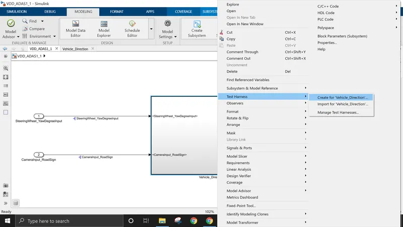
- as we can show in below figure by right clicking on main subsystem go to test harness.
- then click on create for 'subsytem name'
- Then give input signal as Signal Builder and output is outport, we can give any of them which we want.
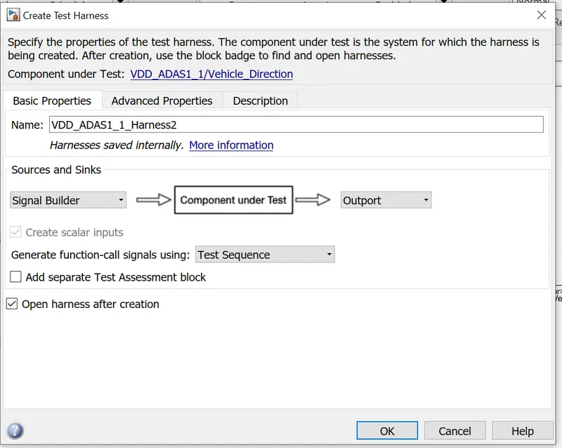
- after click OK.
- it will create MIL test harness in new simulink window.
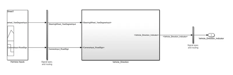
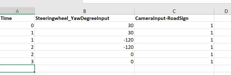
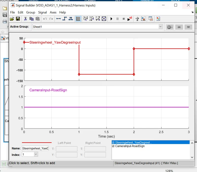
- for testing purpose i added the test data into Signal builder from excel sheet.
- we can add data from excel sheet to signal builder by clicking on 'import from file' option of signal builder.
Creation OF SIL (SOFTWARE IN LOOP) Test:
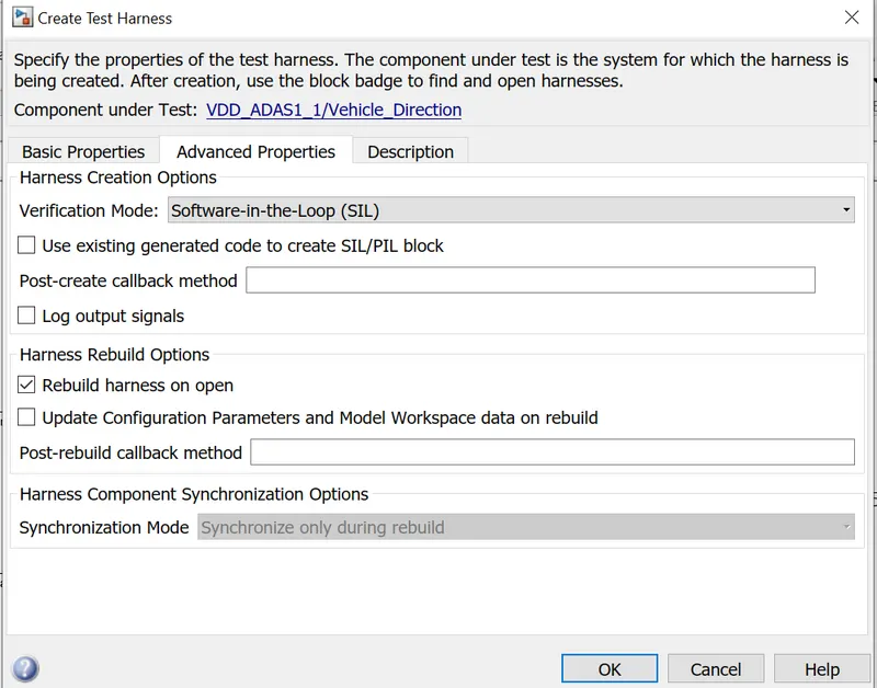
- here in sil testing follow the same procedure as MIL testing.
- But in Verification mode instead of normal we need to give SIL.
- so, it will create new window of SIL testing but unfortunately i dont have embedded coder so cant able to show them to you.
Second Method to create SIL testing:
- After right clicking on a subsytem click C/C++ code.
- then click on 'generate S function'
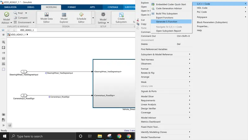
- then it will open this window we need to click yes on Create SIL block.
- then click on Build.
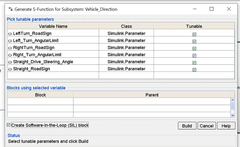
- So, it will open this code and also open the SIL Test harness block in diff window but i dont have installed it in my matlab version,
- so, i cant able to show you but i am able to generate the S function or C code.
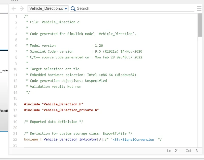
CODE Generation :
/*
 * File: Vehicle_Direction.c
 *
 * Code generated for Simulink model 'Vehicle_Direction'.
 *
 * Model version                  : 1.26
 * Simulink Coder version         : 9.5 (R2021a) 14-Nov-2020
 * C/C++ source code generated on : Mon Feb 28 09:40:57 2022
 *
 * Target selection: ert.tlc
 * Embedded hardware selection: Intel->x86-64 (Windows64)
 * Code generation objectives: Unspecified
 * Validation result: Not run
 */

#include "Vehicle_Direction.h"
#include "Vehicle_Direction_private.h"

/* Exported data definition */

/* Definition for custom storage class: ExportToFile */
boolean_T Vehicle_Direction_Indicator[3];/* '/SignalConversion' */

/* Const memory section */
/* Definition for custom storage class: Const */
const int16_T LeftTurn_RoadSign = -120;/* Referenced by: '/Constant2' */
const int16_T Left_Turn_AngularLimit = -120;/* Referenced by:
                                             * '/Constant1'
                                             * '/Constant4'
                                             */
const int16_T RightTurn_RoadSign = 30; /* Referenced by: '/Constant1' */
const int16_T Right_Turn_AngularLimit = 30;/* Referenced by:
                                            * '/Constant'
                                            * '/Constant3'
                                            */
const int16_T Straight_Drive_Steering_Angle = 0;/* Referenced by:
                                                 * '/Constant2'
                                                 * '/Constant5'
                                                 */
const int16_T Straight_RoadSign = 0;   /* Referenced by: '/Constant3' */

/* Real-time model */
static RT_MODEL_Vehicle_Direction_T Vehicle_Direction_M_;
RT_MODEL_Vehicle_Direction_T *const Vehicle_Direction_M = &Vehicle_Direction_M_;

/* Model step function */
void Vehicle_Direction_step(void)
{
  /* local block i/o variables */
  real_T Vehicle_Turn_Status;

  /* Outputs for Atomic SubSystem: '/Vehicle_Direction' */
  /* Switch: '/Switch3' incorporates:
   *  Constant: '/Constant'
   *  Constant: '/Constant1'
   *  Constant: '/Constant2'
   *  Inport: '/SteeringWheel_YawDegreeInput  '
   *  RelationalOperator: '/RelationalOperator'
   *  RelationalOperator: '/RelationalOperator1'
   *  RelationalOperator: '/RelationalOperator2'
   *  Switch: '/Switch1'
   *  Switch: '/Switch2'
   */
  if (SteeringWheel_YawDegreeInput == Right_Turn_AngularLimit) {
    /* Switch: '/Switch3' incorporates:
     *  Constant: '/Constant3'
     */
    Vehicle_Turn_Status = (real_T)Right_Turn_AngularLimit;
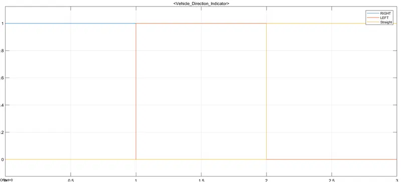
OUTPUT :
- As per the excel sheet our output is matching.
- we can check this output after applying scope block to test harness.
CONCLUSION :
- Test is performed for the developed model using MIL and SIL test for the sample time of 3 sec with 0.01 fixed step time.
- SLDD file is created in model explorer of Simulink.
- requirements are tagged in simulink model from word file.
- model setting is done and then model advisor is also check with 0 error.
- generating the report is also done.
- MIL and SIL test is completed and C code generation is also uploaded.