Project 1-Meshing of Rear Wheel Holder challenge
Meshing of Rear Wheel Holder [Spare Wheel Floor Panel]
Aim -
- To perform preprocessing on the given Rear Wheel Holder [Spare Wheel Floor Panel] Sheet Metal component using hypermesh preprocessing software.
Objective -
- To generate the mid surface manually and do a geometry clean up on the component.
- To generate a mesh and to get a proper mesh flow on the given component with low tria concentration.
- To check the elements quality according to the given quality criteria.
- To assign a thickness for the component.
Theoretical Framework -
Stepney Spare Wheel Floor Panel :
- The Stepney Spare Wheel was invented by Thomas Morris Davies in Llanelli in 1904. At that time, early motor cars were made without spare wheels, so a puncture was an event dreaded by all drivers. Mr. Davies's brilliant idea was to make a spokeless wheel rim fitted with an inflated tyre.
- Pretty soon T. Morris Davies and his brother Walter were in business, turning out spare wheels in their Llanelli works. They became very wealthy men as their business grew and they set up agencies across the world.
- Their 1909 catalogue proudly claimed that Stepney Spare Wheels were fitted to all London taxis. In 1922 the company became Stepney Tyres Ltd and their operations moved from Llanelli to Walthamstow.
- The days of the patent spare wheel had drawn to a close, as car manufacturers began to provide spare wheels with all new cars. However, the name lived on, long after the last spare wheel was made.
- A "stepney" is still today the everyday name for a spare wheel in India, Bangladesh, Malta and Brazil, where it is called an "estepe".
- A further twist to the tale is that in Dehli an easy going member of staff, who is not much help, can also be called a "stepney".
- A spare tire (or stepney) is an additional (tire or tyre) carried in a motor vehicle as a replacement for one that goes flat, has a blowout, or has another emergency.
- Spare tire is generally a misnomer as almost all vehicles actually carry an entire wheel with a tire mounted on it as a spare rather than just a tire, as fitting a tire to a wheel would require a motorist to carry additional, specialized equipment. However, some spare tires ("space-saver" and "donut" types) are not meant to be driven long distances.Space-savers have a maximum speed of around 50 mph (80 km/h).
- When replacing a damaged tire, placing the compact spare on a non-drive axle will prevent damage to the drivetrain. If placed on a drivetrain axle, the smaller-diameter tire can put stress on the differential causing damage and reducing handling.
- A structural shear panel for forming a floor panel for support by a vehicle frame is formed by a composite of top and bottom sheets and a core with a vacuum infused resin.
- The core is formed of top and bottom layers each formed from a honeycomb panel defining an array of hexagonal tubular cells with walls which extend in the thickness direction filled with a foam material.
- A third layer is located between the first and second layers and is formed of a material such as foam, rubber or cork which is free from tubular cells in the thickness direction and free from rigid structural members in the thickness direction to reduce communication of sound through the panel.
Introduction :
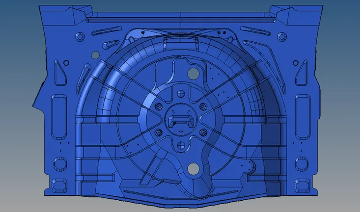
- The component given to us is car stepney spare wheel floor panel.
- This component is a sheet metal component.
- For the plastic and sheetmetal component with the thickness less than 6mm,We have to take a mid surface adn then we have to mesh.
- Sheet metal is metal formed by an industrial process into thin, flat pieces. Sheet metal is one of the fundamental forms used in metal working, and it can be cut and bent into a variety of shapes.
- Countless everyday objects are fabricated from sheet metal.
- Thicknesses can vary significantly; extremely thin sheets are considered foil or leaf, and pieces thicker than 6 mm (0.25 in) are considered plate steel or "structural steel".
Procedure -
Phase 1-Importing
- Hence we are importing a given CAD geometry into hypermesh.
- There are file formates like IGES,STEP,Parasolid where we can import these file formats into any CAD,CAE Softwares.
- But in hypermesh we can only import three file formates like
- IGES [Initial Graphics Exchange Specification].
- STEP [Standard for the Exchange of Product Model Data].
- Solidworks.
- IGES,STEP,These two are standard file formats which are used most in industries.But now a days in industries,they are aslo using parasolid file format.
- While importing the file into the graphical user interface,Be sure whether the file is .step or .iges file.
- File > Import > Import Model > File type > Open File > Import File.
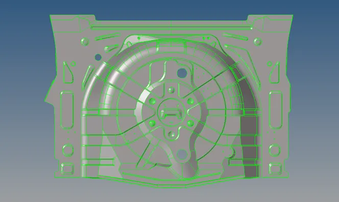
- Switch to the topo mode and examine whether the solid exsist in the component or not,If solids exsist,Delete the solids cause we are doing 2d meshing on the component.
- You can find topo mode in the tool bar panel.
- Delete [F2] >> Solids >> Select by box selection >> Delete Entity.
- If solids exsist,It will be highlighted in the green colour.
Phase 2- Examining
- Before working on the model.We have to check the geometry if there are any errors like
- Damaged Geometry.
- Free edges in unnecessary areas.
- Unnecessary points on the lines.
- Unnecessary Connections and connectivity error.
- There are some free edges in the model,So clear that free edges in the parent component,Then only you can extract mid surface properly without any glitches in the mid surface geometry
2:1 Inspecting
- While inspecting the model,It is a spare wheel floor panel which is used to keep the spare wheel in the car.
- While observing the model,There are 17 [Seventeen] components in the model.
- Organize them to a single component or delete the unnecessary components.
2:2 Organizing
- We use organize tool to (re)organize your database by copying or moving data (entities) among collectors, includes, or parts.
- Select an entity type to copy/move, then use the selector to select specific entities to copy/move. The current collector serves as the default destination.
- Elements can be copied/moved into component collectors or groups.Lines, surfaces, solids, points, and connectors can be copied/moved into component collectors.
- Here we are selecting the collectors and we are organizing it to one collector.
- Tool >> Organize >> Collector SubPanel >> Switch to Surfaces >> Select by Collector >> Move
2:3 Check for the Thickness
- Now go and measure the distance in every region.
- We are ensuring whether some regions of this component having uniform thickness or not.
- The component given to us is sheet metal component.
- The thickness of this stepney floor panel is 0.75 mm.
- You can measure the thickness by two methods.
i) Geometry > Dimensioning > Select the Point1 and Point2.
2:4 Check for Symmetry
- This tool is to find symmetrical surfaces or compare selected surface sets for symmetry. You can reorganize found symmetric surfaces into separate components or delete one subset of a pair of symmetric surface sets.
- This can be helpful with highly symmetrical components, because you can then perform geometry cleanup on only one half, mesh it, and then mirror the mesh instead of having to clean up the entire component prior to meshing.
- Geom >> Surface Edit [Shift + F9] >> Symmetry >> Axis >> Base Point.
- Find symmetry-Locate surfaces within a single component that are mirror images of one another across a plane of symmetry that you specify.
- Delete Positive-Delete the symmetric surfaces on the positive side of the symmetry axis. Used when finding symmetry.
- Delete Negative-Delete the symmetric surfaces on the negative side of the symmetry axis. Used when finding symmetry.
Phase 3 - Geometric Clean Up on the Parent Component
- If we want we can do geometry clean up on the parent component or after extracting the midsurface also, we can do geometry clean up on mid surface.
[Note:No need to work on the parent geometry,After Extracting the mid surface,We can do a geometry clean up on the mid surface,If we work on parent geometry,It will take lot of time,So try to skip]
3:1 Check for Geometric Deformations
- We should also check for any geometric deformations like
- Damaged Geometry in some regions.
- Overlapped Surfaces.
- Free edges.
- Unnecessary Connections (Extra points and lines).
- Connectivity error.
| Figure 17-Damaged Surfaces. |
- Here i'm doing geometric clean up on the parent component,There is no need to work on parent geometry,If you want you can work on parent geometry or it's fine.
- Now fix this damaged surface by deleting the surface.
- Geometry >> Quick edit [F11] >> Delete Surface >> Surface (Select).

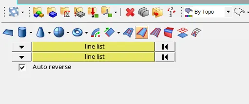
- Now fill this gap with ruled surface,
- Use the first selector to define the first edge of the surface to create. Use the second selector to define the second edge of the surface to create.
s
3:2 Fixing Damaged Geometry in surfaces.
- Deformed surfaces occur due to the following reasons like
- Overlapping surfaces
- Connectivity issues
- Sometimes this issue occurs due to replacing the points multiple times
- These issues can be rectified by using the tools called
[Note:Try to avoid replacing points.Instead of that split the surface and connect.]
- We can fix the geometry by quick edit tools.
- There some sub tools in the quick edit panel,I have described every tool below,Have a look.
i) Geometry >> Quickedit >> split surface node.
- Select two locations of the nodes to split the surface and then select an additional node to continue to split the surface.
ii) Geometry >> Quickedit >> Split surf-line
- In this,select a node and select a line to split the surface,here the split will be perpendicular to the line chosen.
iii) Geometry >> Quick edit >> Adjust/set density.
- After meshing a particular surface.We can adjust the mesh density by using this tool.While meshing we will increase the
nodes to get a proper mesh flow.We can also increase nodes after meshing by using this tool.
iv) Geometry >> Quick edit >> Release points.
- Drag and select the surface,where you want release the points.After releasing the points.The free edges will exsists.
v) Geometry >> Quick edit >> Replace points.
- Move points from their current locations to the locations of other points,where we want them to replace it.
vi) Geometry >> Quick edit >> Add/Remove points.
- Use window selection (with the left mouse button and right mouse button ) to add and remove any points within the
selection box.
vii) Geometry >> Quick edit >> Add points on line.
- Specify the number of points that we wish to add to that line, and then select the desired line in our model.
viii)Geometry >> Quick edit >> Delete surface.
- Select the surface which we need to eliminate and delete it.
3:3 Filling Gaps on the Parent Geometry
- As we are doing auto mid surface extraction for this component,So try to fill the gaps in the parent geometry.
- You can also extract auto mid surface without filling gaps.
- We have to close the gaps,where there are free edges in the geometry.
- It will be very difficult to find the small free edges.
- So go to the Visualization tab .
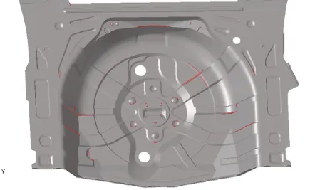
- The gaps which are narrow,We can toggle them using Quick Edit Panel.
- Geom >> Quick Edit [F11] >> Toggle Edges >> Lines (Select).
Toggle Edge -
- Use the lines selector to select line(s).
- Left-click a free edge (red) to make it shared (green), or a shared edge to make it suppressed (blue).
- Right-click a suppressed edge to make it shared, or a shared edge to make it free.
Filler Surface -
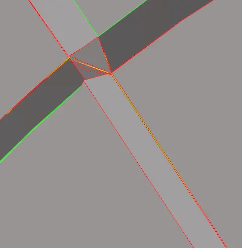
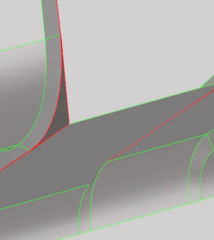
- This tool is used to fill the gaps which are bigger.
- Use the line(s) selector to select a closed-loop line (a hole) in your model to create a surface that fills the hole.
Phase 4 - Extracting Mid Surface
- The midsurface has been extracted to the components which have less than 6mm thickness.
- We will be extracting midsurface for the sheetmetal and plastic components.
4:1 Why to Extract Mid Surface ?
- Before extracting the mid surface for every component,We should measure the thickness of the component and then we have to proceed to extract the mid surface.If the component thickness is less than 6mm then we will come to know it is a sheet metal component or plastic Component.
- For sheet metal and plastic components,Mid Surface extraction is must.
4:2 Midsurfacing: Process & Strategy-
1.Obtain a closed volume of surfaces or solids
- Midsurface : Auto midsurface requires an enclosed volume.
- Use topology repair techniques if needed.
2. For complex parts, try defeaturing the surface defining the volume
- This simplifies the part and may give better results with create solid.
3. Generate the midsurface using midsurface : auto midsurface
- Use surface pair for areas that need more control.
- Use midsurface : editing tools for midsurfaces that need fine tuning.
4. View the midsurface and correct errors using the midsurface editing functionalities
- Can generally use quick edit.
4:3 Extract the Mid Surface
- For this component,I'm using auto mid surface extraction.
- Auto Midsurface is used to to extract the midsurface of a more complicated group of surfaces that represent a solid part in one step.
- I'm extracting midsurface by Offset + Planes + Sweeps,Because this component has many features and sweeps.
- Offset + planes + sweeps-It is used to identify the places where a piece of plane or a piece of a sweep surface can be used as a middle surface. A middle surface is constructed at the remaining places in the model, for example the places where planar or sweep surface pieces cannot be used as a middle surface, by the same algorithm as in offset via the offset of the model's sides.
- Geom >> Mid surface >> Auto Midsurface >> Extraction process (Offset + Planes + Sweeps) >> Auto Extraction (Closed Volume) >> Surfaces (Displayed) >> Extract.
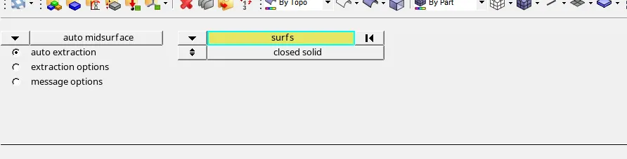
- The mid surface created will be assigned to a new collector called Middle Surface.
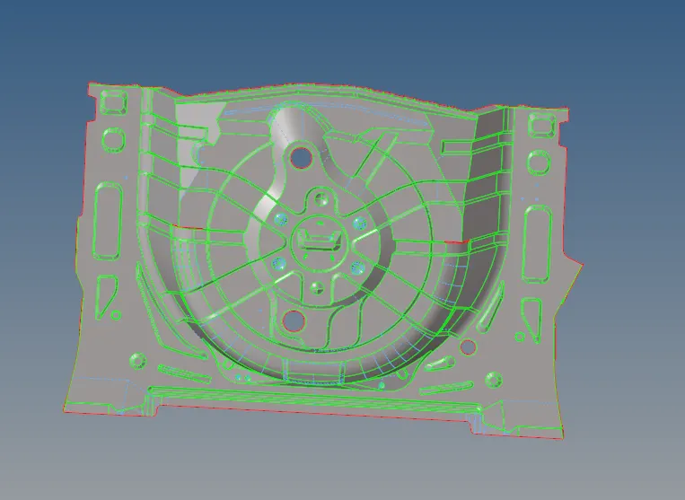
| Extracted Mid Surface. |
4:4 Check for the Duplicate Surfaces
- Sometimes,The duplicates surfaces may occur while extracting the mid surface.
- So check for the duplicates,Give a Clean UP Tolerance value as 0.1 and check.
- Geom >> defeature >> Duplicates >> Surfaces (Displayed) >> Cleanup Tol = 0.1 >> Find >> Delete.
Phase 5-Geometric Clean Up on the Mid Surface
- Do a geometric clean up on the mid surface extracted.
- Check for the free edges in the middle region of mid surface.
- If there are any free edges,Toggle them and eliminate that free edges.
5:1 Filling Gaps on the Surfaces which or not filled
- We need to fill the gaps (Free Edges) to get a connectivity while meshing.
- If we won't fill the gaps,There will be no connectivity while meshing.
- If we do analysis without filling that gaps,Forces won't be distributed in that regions,So fill the gaps and equivalence them.
- We can fill the surfaces by using following tools called
- Filler Surface
- Ruled Surface
- Spline
- Skin
i) Filler Surface -
- This tool is used to fill the gaps which are bigger.
- Use the line(s) selector to select a closed-loop line (a hole) in your model to create a surface that fills the hole.
ii) Ruled Surface
- We can also fill the gaps using ruled surface.
- Ruled Surface is used to create surfaces by interpolating linearly between lines or nodes.
- Line List-Use the first selector to define the first edge of the surface to create. Use the second selector to define the second edge of the surface to create.
- If a node list is selected, a line will first be fit through the specified nodes.
- Go to Geometry >> Surfaces >> Ruled Surface >> Select Line List 1,2 >> Create.
iii) Spline
- We can use the Spline/Filler tool to create surfaces by filling in gaps, such as a hole in an existing surface.
- Select the lines, node list, or points that define the spline/filler area.
- Lines-Select two or more lines. The lines do not have to form a closed loop, as disconnected lines are first connected with straight lines. Both free lines and surface edges can be selected.
- Go to Geometry >> Surfaces >> Spline/Filler >> Select Lines.
5:2 Fixing Deformed Surfaces
- Due to complexity of the features,The software was unable to extract a good mid surface.
- There are some surfaces overlapping and there is no connectivity ,So fix this manually.Do a manual geometric clean up
5:3 Delete Small Holes
- Delete the small pin holes because we can't capture the feature there.
- So delete that samll pin holes,After deleting that fill that holes with the filler surface.
- Delete tool is used to delete data from a model database, preview and delete empty collectors, and preview and delete unused property collectors, material collectors, or curves.
- You can also delete an entire model database, if you wish to start with a clean database.
- Go to Tool >> Delete [F2] >> Surfaces >> Delete Entity.
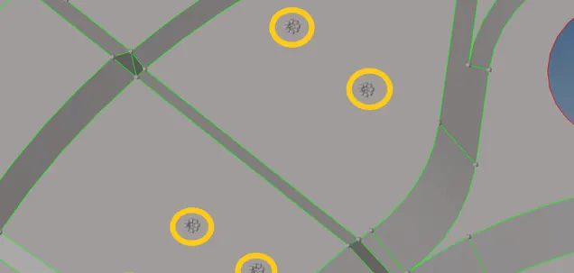
Phase 6 - Perform Mesh on the Surfaces
- Once geometry cleanup is completed (e.g. surfaces are stitched together — no unwanted free surface edges inside the geometry), meshing is next.
Some rules of thumb when meshing:
- The mesh should look rather smooth and regular (keep in mind that the analysis is based on your mesh and the mesh quality is key.
- Use the simplest element type suited for the problem.
- Start with a coarse mesh and understand the modeling results; then use a finer mesh if needed.
- Try to keep mesh related uncertainties to a minimum if possible. Keep it simple as it can get more complicated on its own.
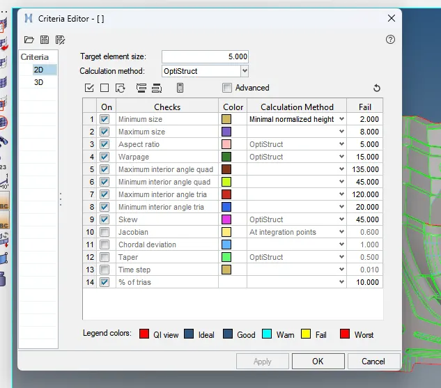
- Important Parameter's in tria management
- No trias in corner's or edge's.
- No opposite trias.
- No back to back trias.
- No trias in fillets or hemmings(We can have minimum but anyhow try to avoid).
- No rotational quads.
- No trias should share a boundary with feature line.
- Connectivity between elements.
- Split and perform the mesh.
- Use mixed type mesh for irregular shaped surfaces and quads only for rectangular/square surfaces(Opposite sides should be parallel and equal).
6:3 Begin meshing the surfaces
- Start meshing from the centre regions or from least free edges.You will get proper mesh density and proper mesh flow.
Why Meshing is Needed ?
- Finite Element Method reduces the degrees of freedom from infinite to finite with the help of discretization or meshing (nodes and elements). One of the purposes of meshing is to actually make the problem solvable using Finite Element. By meshing, you break up the domain into pieces, each piece representing an element.
How to Begin Mesh ?
- Start meshing form the least free edges,Like start meshing from the center.
- It will be easy to get proper mesh flow and we will get uniform mesh density.
- Don't mesh form the edges,It will be difficult and you will get many error,So start meshing from the center.
- Choose the element type while meshing.
- For this component we will be using mixed element type and working on it.
- We can also quads element type.This type can be used when we have rectangular surface.
- We can use Tria Element type.This type can be used for 3d tetra meshing.
Start Meshing
- Now start meshing on the surfaces,Go to 2D >> Automesh Panel >> Surfaces >> Element size = 5mm > Mesh Type : Mixed >> Check for align and size >> Mesh.
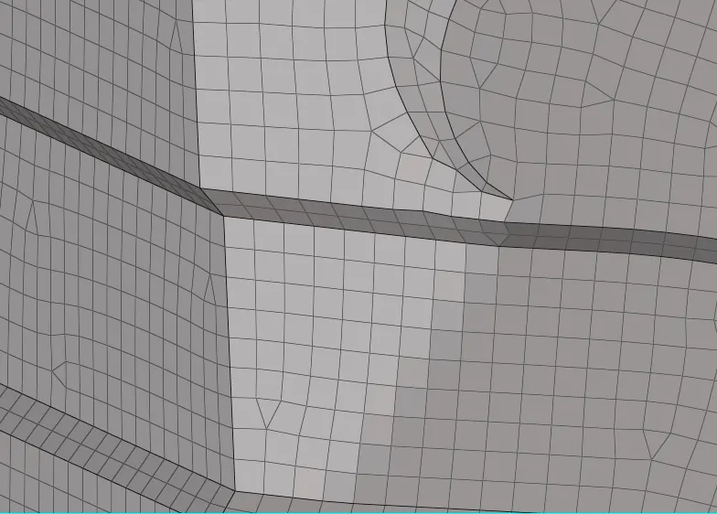
- Select the appropriate mesh type based on the shape of the surface.
- Once we give for mesh, we can edit the mesh density by changing the number of nodes.
- Here i have splitted the surface to rectangular surface and meshed to get proper mesh flow.
- Make sure to check the Link Opposite Edges with AR.
- This option is to be checked when your are meshing on the rectangular surface.
- Link Opposite Edges with AR-[Eg:If we have 29 nodes on left side edge,It will project the same 29 nodes on right side edge.]
- Now if we mesh on the curved surfaces,Choose the mesh type as mixed and mesh.
- If we choose quad mesh type,The mesh will fail,It won't occur on the surfaces.
6:4 Remesh and Rebuild Mesh
Remesh-
- Remesh is used to generate a mesh of plate elements using surface geometry or existing shell elements to define the mesh area.
- Elements are remeshed with the use of the HyperMesh inferred surface algorithm, if geometry for theselected elements needs to exist in the model.
- The inferred surface algorithm interpolates geometry datafrom the selected elements in order to create new mesh.
- When elements are selected to be remeshed, there is the break connectivity option and the vertex angle parameter. The break connectivity option detaches the node connectivity between adjacentselected and unselected elements. This allows you to adjust the node densities along the boundary ofthe selected elements.
- The vertex angle parameter defines the placement of vertices along theboundary of the selected elements. If the angle between two adjacent element edges along the boundaryis less the specified angle, a vertex is placed at the meeting point of the two edges.
- Anchor nodes create the effect of a fixed point on the inferred surface (which is derived from the existing mesh) and keep the location of the anchor nodes intact.
Rebuild Mesh-
- It is the process of remeshing existing meshes to generate a new mesh with good quality and flow.
- The rebuild mesh functionality utilizes the same parameter and criteria files used by BatchMesher to define the quality criteria and relevant mesh parameters.
- This algorithm saves significant time over the traditional automesh and quality correction approach.
- Rebuild is currently supported for first-order 2D meshes that are not attached to 3D element faces.
- The rebuild algorithm is useful for many different applications like
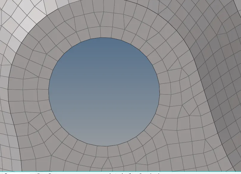
- While meshing the surfaces having circular hole.
- Make sure to create even number of nodes.
- For this component and for this circular holes i will be creating 20 even number of nodes,You can also go with 18 or 16.
- Make sure that the element edge should be aligned parallel to the shared edge.
6:7 How to get Proper Mesh Flow ?
- After fixing the quality in mesh.Do the smooth operation on the meshed regions.
- You will get a proper mesh flow,While smoothening some elements may fail like 1 or 2,So try to clear them with distance tool.
- To use smooth tool,Go to 2D >> Smooth >> Elements >> Size Corrected >> Smooth.
- Smooth tool will improve element quality in a surface-based mesh or a mesh of solid elements using one or more algorithms that adjust node positions to moderate sharp variations in size or quality in adjacent elements.
- Iterations specifies the number of passes you wish the smoothing algorithm to run.
6:8 Aligning the nodes across edges and align nodes to get proper mesh flow
- After smoothening the elements,Some elements may not be aligned.
- To make them align we can use align nodes tool to align them.
- Go to Geometry >> Node Edit >> Align >> 1st Node >> 2nd Node >> Align
- Align Nodes across edges - If the nodes are not projected to the edges,then you can use project tool to project or align them cross edges.
- To Project go to Tools >> Project >> To Line >> Select Nodes >> Normal Lines.
- It is used to project nodes or points to a line along a user-defined direction or the normal to the line selected.
6:9 Manual Clean Up Using Distance[F4] and Translate[Shift +F4].
- We can use the Distance tool to determine the distance between two nodes/points or the angle between three nodes/points, or to change distances or angles.
- We can also fix the elements failing for the quality like
i) Minimum and Maximum Length
ii) Minimum and Maximum Quad
iii) Minimum and Maximum Tria
iv) Aspect Ratio

- Similarly we can fix elements failing for min and max quad,min and maax tria ,aspect ratio using distance tool,Sometimes we can also fix warpage.
- But better to use translate tool to fix warpage.
- We will be translating the some warpage angle to the neighbour element,by using translate tool we can easily fix the warpage.
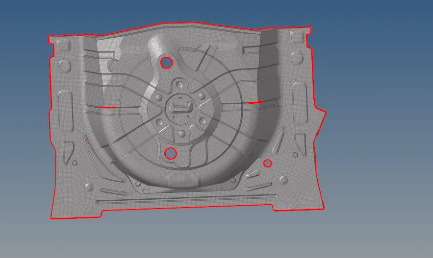
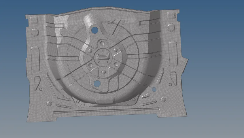
i) Check for Connectivity [Free Edges]
- Edge Tool will help us to find this error.
- Go to Too >> Edge >> Elements >> Find Edges.
[Note:While checking free edges,Give the tolerance value as .01.If it is an assembly component,Give tolerance value as .01.It should not exceed more than .01 for assembly check.
If you give high tolerance and click preview equivalence,the software willl show you,many nodes are connected.So go give lower tolerance for the assembly components.Dpn't go betond normalized minimum height.The minimum normaalized height for this component is 2.0.]
ii) Check for Duplicates
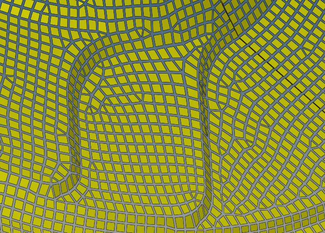
- Now check for the duplicate elements
- To check duplicates,Go to Tool >> Check Elements >> Duplicates.
iii) Check for Normals
- We can Use the Normals to display and reverse the normals of elements or surfaces. The orientation of element normals can also be adjusted. The normal of an element is determined by following the order of nodes of the element using the right-hand rule.
- Normals can be reviewed showing a vector or by colors. A vector shows in positive normal direction, while the color mode shows the positive side of a shell or surface in red and the negative side in blue.
- To check normals go to Toolbar >> Mesh >> Check >> Elements >> Normals.
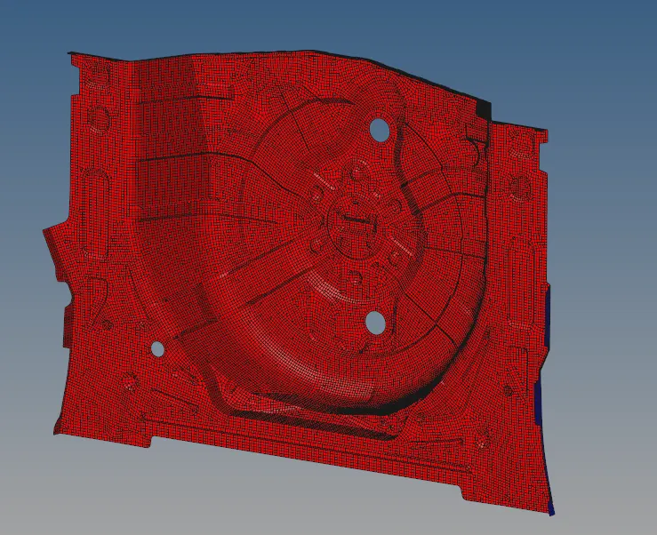
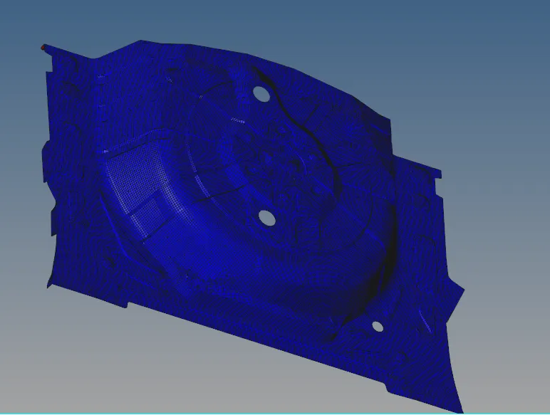
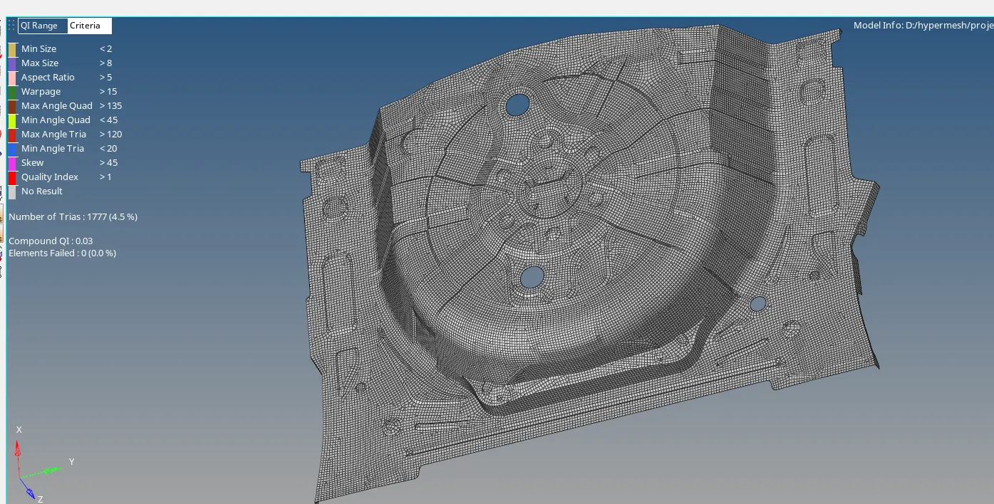
Final Mesh Model -
Phase 7 - Assigning Thickness to the Elements
7:1 Check thickness in geometry
- First check the thickness in every region and then assign a thickness by creating a collectors and organize it to that newly created collectors.
- Check thickness by distance tool or by dimensioning tool.
- Geometry >> Distance >> Two Points >> Point1,2.
- Geometry >> Dimensioning >> Point1 >> Point 2.
7:2 Create a Collector
- After measuring thickness,Create a component and rename it as Middle Surface_1 2.8mm [Base Surface].
- Don't organize elements in the base surface,Just rename it as Middle Surface_1 2.8mm.
- Organize the elements in ribs and cylindrical ribs to the newly created collectors.
7:3 Assign Property to the Components
- First Create a property on the browser.
- To create a property,Right click on browser >> Create >> Property.
- After Creating a property rename it and start assigning thickness to the components.
- Now check the complete model,Whether the property has been assigned to the collectors.
- To Check Go to Menu Bar >> Tools >> Component Table.
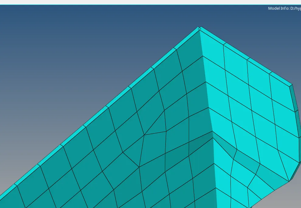
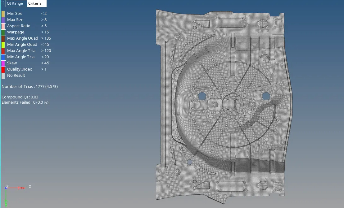
Final CAD Model Image -
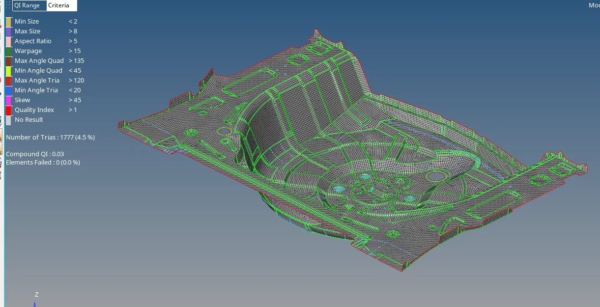
RESULT
- Hence the mid surface has been extracted from the parent geometry.
- Hence there are no surface deformations in the geometry.
- A well connectivity has been established between the surfaces.
- The features have been captured properly.
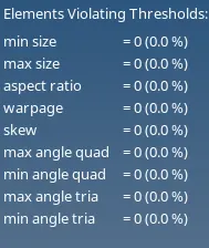
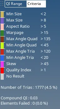
- A good mesh flow have been achieved with the zero elements failing for quality
- Hence tria percentage with4.5 % have been achieved.
Learning Outcome and Conclusion -
- In this project,I came to know
- How to mesh a complex sheetmetal component.
- How to extract the mid surface manually for the complex sheetmetal components.
- How to clean complex geometry .
- How to generate a proper mesh flow with low tria percentage.
- How to assign thickness to the components.