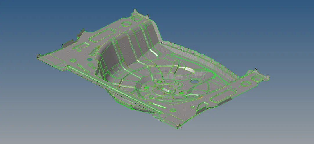
Project 1-Meshing of Rear Wheel Holder challenge
StepsFollowed:-
1. Since this component has multiple collectors, the first step is to sort them all out. By relocating every collector to the first one and then removing the empty ones, we can merge all of the collectors into a single one. This will assist in avoiding any potential misunderstanding. The 'organize' tool (Tool > Organize) is used for this. Before clicking Move, we must first choose the surface that has to be relocated and the destination surface.
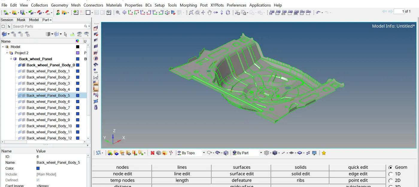
Next, by right-clicking and choosing create > component from the collector menu, we can make a new collector that we'll call "Midsurface."
2. We may proceed to manually build the midsurface from the bottom because the component's thickness is nearly the same throughout. This is because some areas of the geometry are very intricate. We'll need to gauge its thickness in order to do this. that is 0.75 mm. (To open the Thickness tool, press F4). This is necessary for the manual midsurface construction process. And the offset tool in Surface Editor is used for this.
3. We must confirm that the newly formed midsurface component is our current component before moving on to the next step. (By right-clicking on the specific collection and choosing the'make current' option, we may make a component the current one).
4. A measurement half the thickness is needed for the offset tool. which, in this instance, would be 0.375 mm. Geometry > Surface Edit > Offset is the shortcut to the offset tool. From among the faces, we are able to choose any one of them. or Using automidsurface we can generate the mid surace.
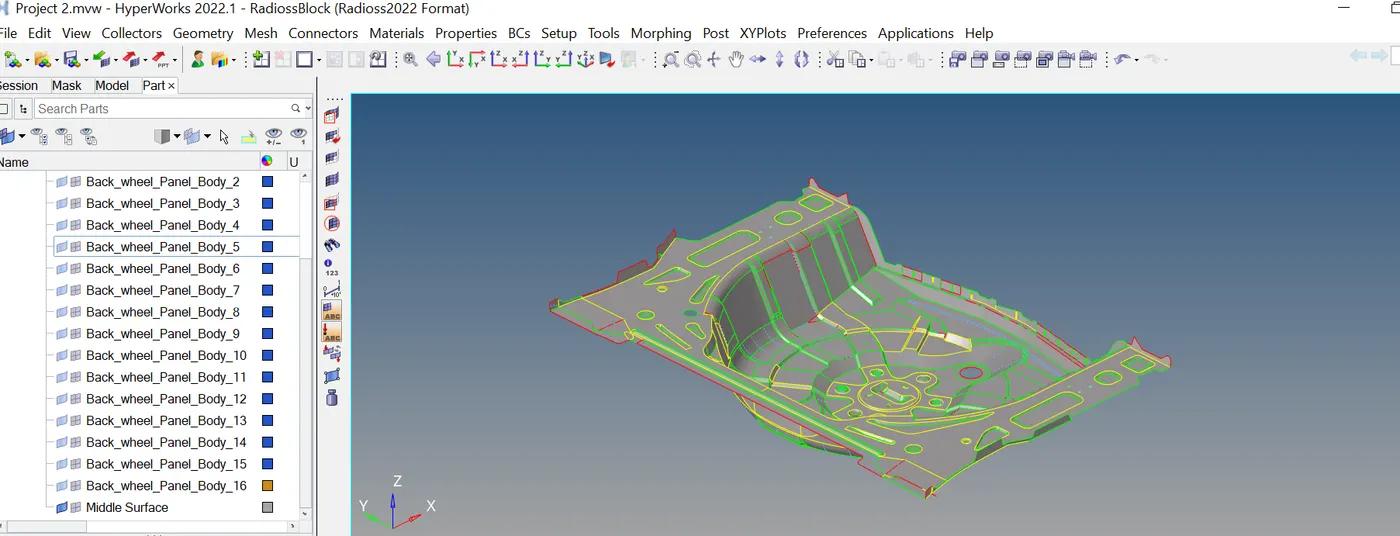
5. Some housekeeping is necessary; the red-marked free edges indicate where they have appeared. The toggle tool can be used to fill in spaces between surfaces. The majority of the free edges observed here will result from it. Geometry > Quick Edit > Toggle Edge will bring up the toggle option. The gap is then stitched by clicking on one of the free edges.
6. The quality parameters are initially entered in the criteria file settings as given (Preferences (Toolbar) > Criteria File Settings) after the midsurface has been cleaned up and before meshing.
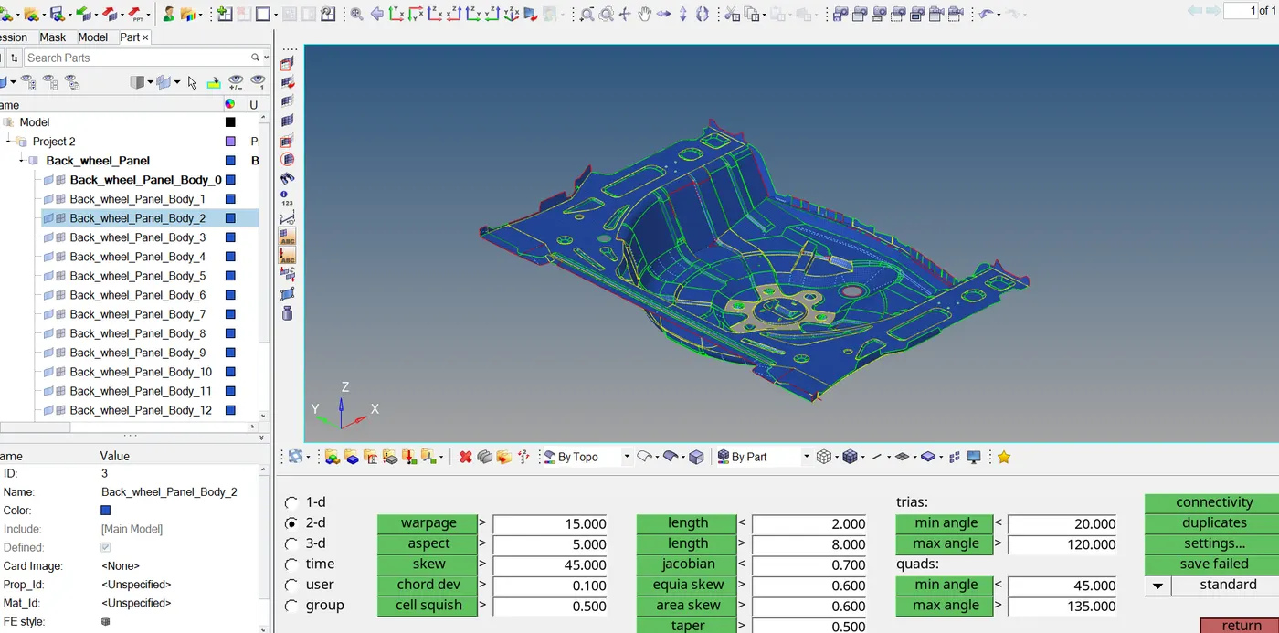
We should begin meshing from a certain location and work our way out of it, as is common with meshing (ideally one with more free edges). To aid in this, we can divide the surface into smaller surfaces for improved mesh control by using cut lines (quick edit > split surface node). The 2D set of settings provides access to the automesh tool. The length of the target element is 5 mm.
In order to ensure that the surfaces we design do not promote tria formation (such as sharp edges), we also need to toggle lines that might impede mesh movement.
We can use a variety of techniques to clean the mesh once it has been constructed. We will mostly use the drag tria tool, the element optimize tool, and the swap edge tool to a lesser amount. These can be accessible using the 2D menu's quality index section. In addition, smoothing will be needed after dragging trias. You may get to it by selecting 2D > Smooth. Trias in opposition are pulled in the same direction and eliminated. Next, the impacted areas are refined:
We can proceed to the next surface after taking care of the previous one (mesh and cleanup). Until the entire component is mesh, the operation is repeated.
7. We may utilize the reflect tool (Tools > Reflect) to generate the other symmetrical half of the component, saving time because some portions of the component are symmetrical. First, we must decide which elements to reflect. Because both halves may not be perfectly symmetrical, be careful not to choose areas that are not otherwise a part of the other half. After that, we may choose the base point and the axis on which we are reflecting. Following that, 'Elements' in the reflect toolbar must be right-clicked, then duplicated. Next, we can select "Reflect." By doing this, the current component's mirrored half will be created.
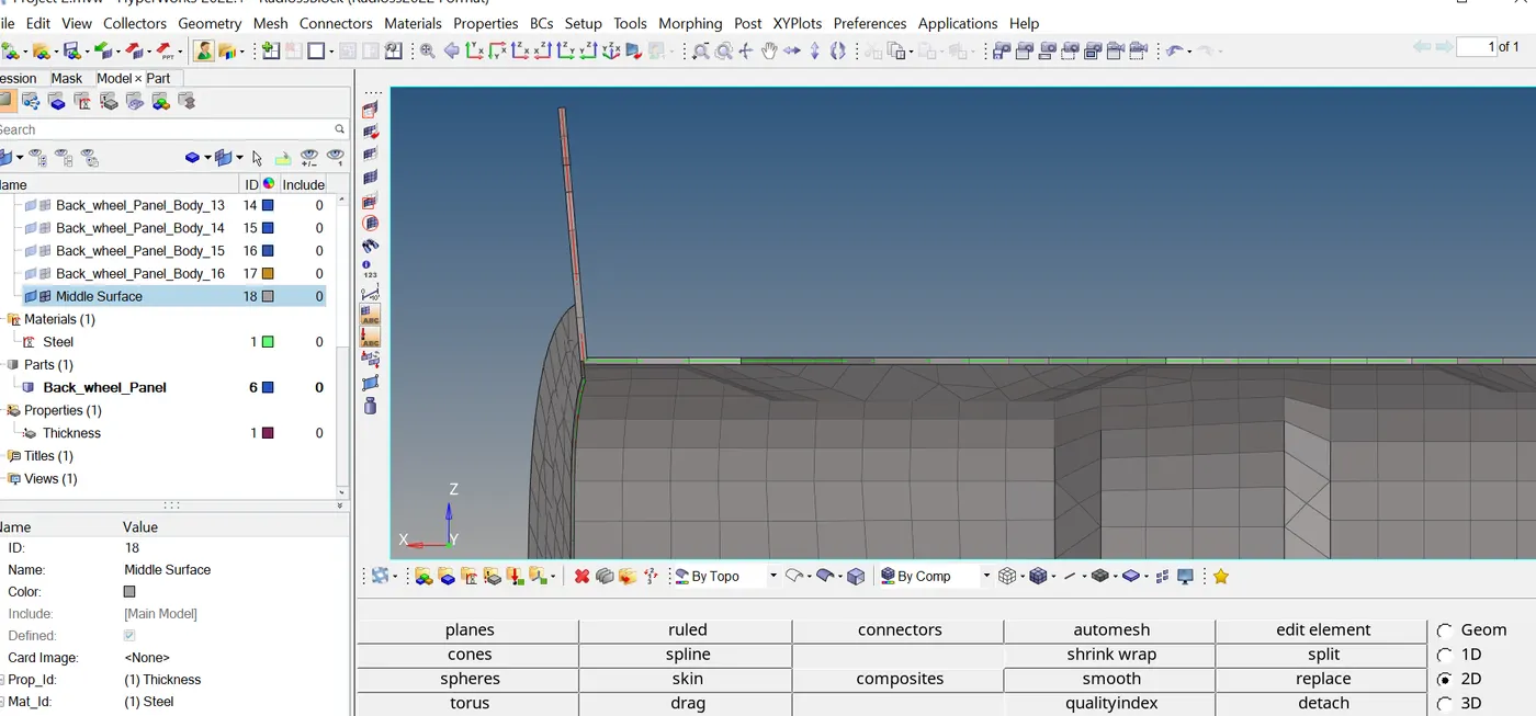
8. Lastly, we can give each of our midsurfaces a thickness of 0.75 mm. By performing a right-click and building a component in the component tree, we may accomplish this. Once 'Thickness' has been created as a property, we can choose it by going to its section on the bottom left and scrolling down to assign the previously indicated thickness.After choosing the midsurface, we can assign the thickness by selecting the thickness property in the properties box located on the bottom left of the box.
After choosing the midsurface, we can assign the thickness by selecting the thickness property in the properties box located on the bottom left of the box.The way the material is made is similarly comparable,
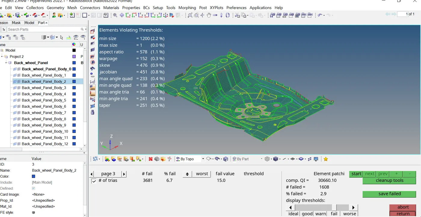
We can now give it the name steel and set the attribute to the midsurface in the bottom left entity editor box (as seen in the screenshot below). Before the property may be assigned, it must be chosen.Because meshing surfaces with tight dimensions is an inevitable process, some elements were certain to fail. To solve this problem, they could have been toggled, but doing so would have interfered with surface capturing. They were therefore already meshing.
RESULTS
As a result, the specified floor panel was meshed after the midsurface was extracted. Meshing was carried out in accordance with the needed quality criteria, and the mesh flow was kept as smooth as possible. There were failed elements due to the need to assure appropriate surface capture.
The thickness and substance of the midsurface were also determined.
Link : https://drive.google.com/file/d/17coV0Ufh7S2yuNVCId5iV1K_Kubtd3dg/view?usp=drive_link