Project 1 - Meshing of Floor Panel
Aim:-To mesh the sheetmetal object i.e. floor panel with extraction of middle surface using appropriate method
Objective:-
- Geometry Cleaning
- Midsurface Extraction using appropriate method and assigning respective thickness.
- Generation of 2D Mesh as shell using batch mesh.
- Converting the generated shell mesh to solid and comparing with actual component.
Procedure:-
- Loading the given component from stored location. checking the surfaces for defects like overlapped faces. unwanted areas.,etc..
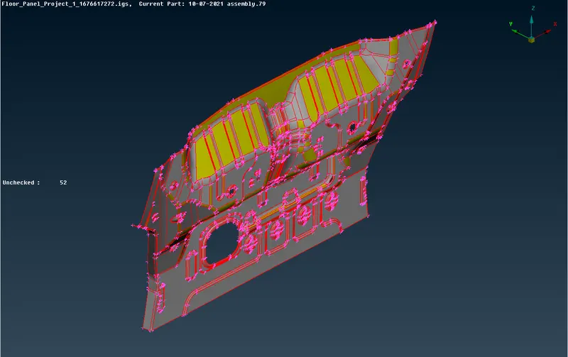
- Then setting the element length initially to 1 and giving Topo so all the neaby surfaces gets connected and form double cons.
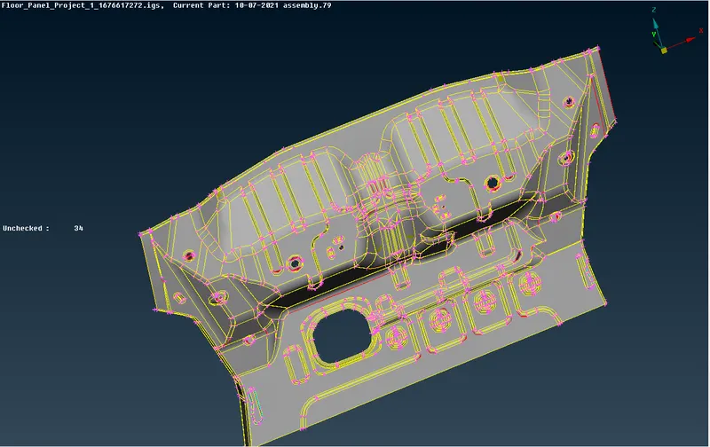
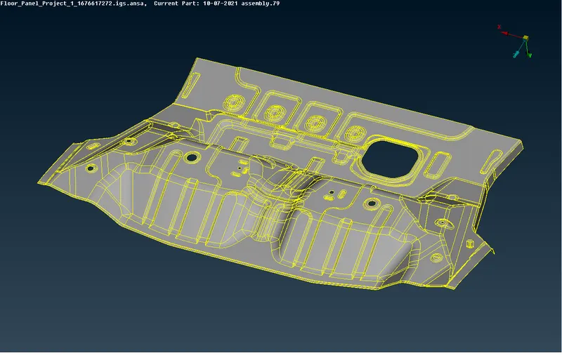
- The component is checked for Triple cons, Single cons & overalpped surfaces.
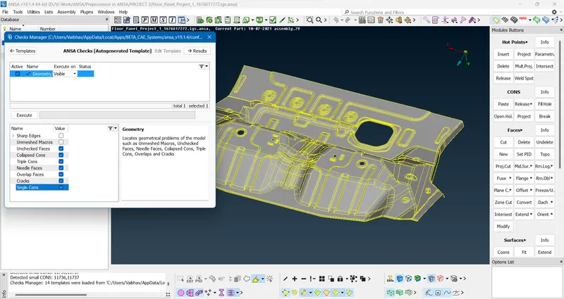
- There were some few triple cons and single cons present in the geometry.
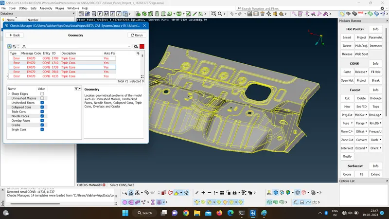
- The triple cons are removed by removing unwanted surfaces and adding new surfaces. Only the single cons present at the edge are left unchanged. And unnecessary hotpoints are removed.
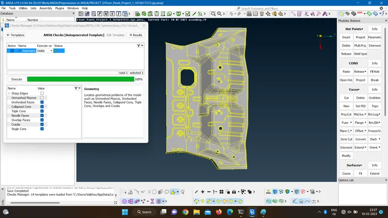
- The given element length is feeded.
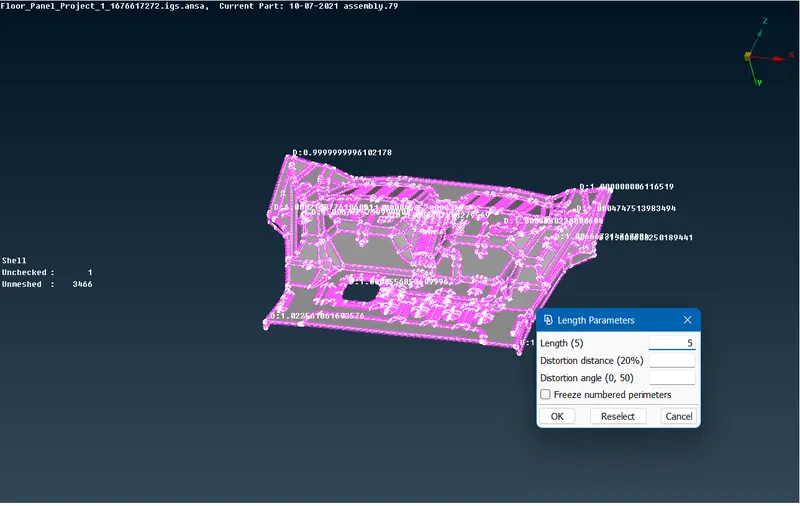
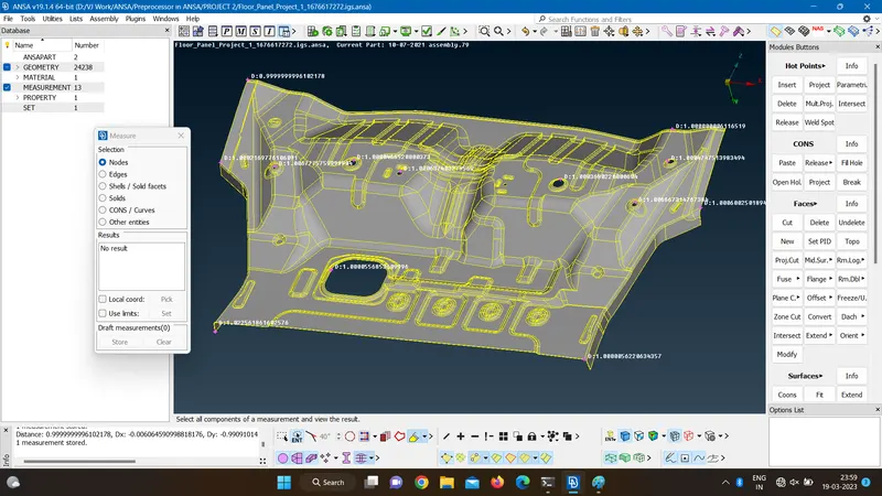
- The geometry is measured at various sections and it has even thickness so auto mid surfacing is possible.
- so the midsurfacing is done by skin command in Topo module by manually selecting red, green and blue surfaces.
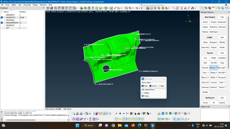
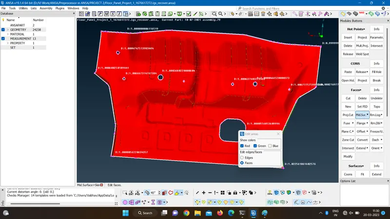
- Thickness of 1mm is automatically detected by ANSA and the midsurface is generated.
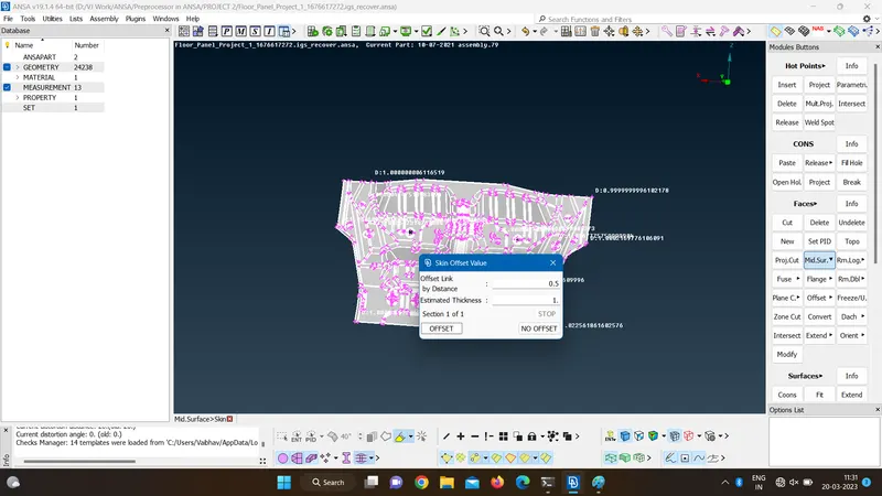
- New PID is assigned to the midsurface with thickness assigned as 1mm.
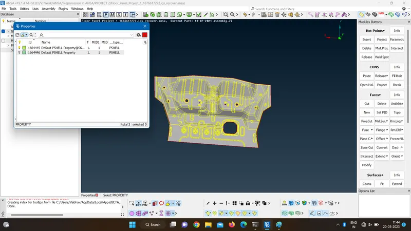
- The extracted midurface is copied and set as current part in model browser.
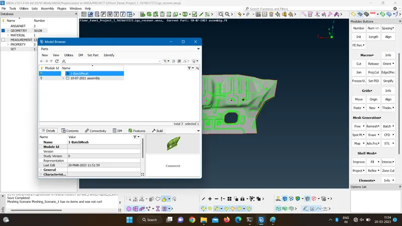
- The given quality criterias are entered.
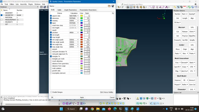
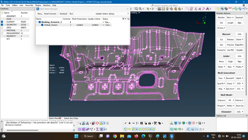
- A new mesh scenario has been created with selected part and given parameter file and quality criteria in bach mesh option.
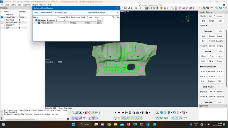
- The batch mesh command is then run.
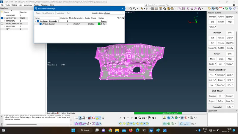 rul
rul- And the mesh geometry is then obtained after successful run.
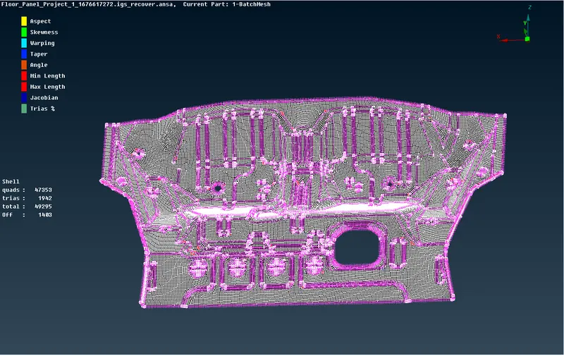
- Mesh surface is checked for quality which had total 49295 elements out of which 47353 were quads and 1942 were trias and 1403 were off elements.
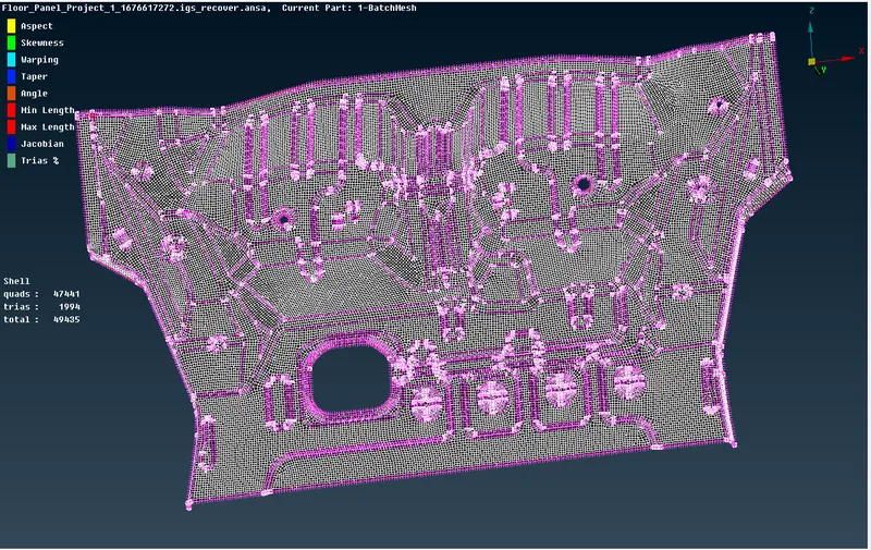
- The quality errors are cleared using swap, join and split, reconstruct, reshape, smooth commands.
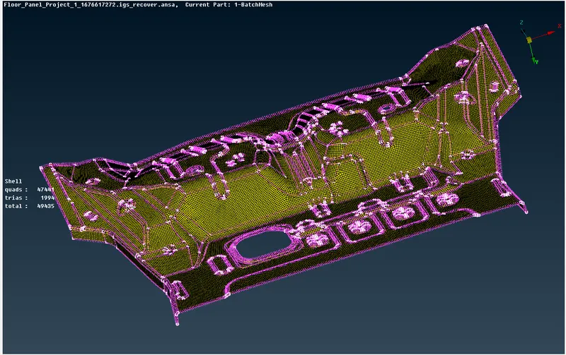
- the mesh shell body is compared with 3D geometry by enabling the draw shell as 3D solid.
Conclusion-
As the component had even thickness, the middle surface is extracted using auto method and thickness is automatically assigned to surface and properties are created for the thickness. The extracted surface is then mesh using batch mesh for better results and faster processing. model is checked for quality and then compared with 3D geometry.