Project 1 - Meshing of Floor Panel
Objective:
The primary objective of this project is to generate an effective meshing of the given component by following geometry clean-up, Material and thickness selection, mid-surfacing and then finally meshing of the given Floor panel without any failure in the elements.
Procedure:
<!-- [if !supportLists]--> I. <!--[endif]-->Import the given CAD model of floor panel
The CAD model in .stp file is imported into the ANSA software by clicking File > New command.
<!-- [if !supportLists]--> II. <!--[endif]-->Geometry Check:
The imported model found with many unclean errors like cracked faces, unwanted cons. To clean the error, the model should pass geometry check by choosing the command Tools > Checks > Geometry.
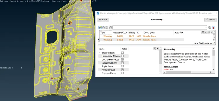
By executing the tool, found almost 260 errors with the model. I tried to clear the unclean issues by fixing automatically using command “Fix” and cleared most of the errors. Still the model had major errors like surface cracks, single cons, etc.
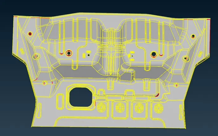
I tried to release all cons and removed unwanted hot points and then followed Topo check to fix the geometry using command Faces > Topo.
This helped me to identify all the unwanted cracks and cons easily in red as below.
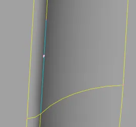
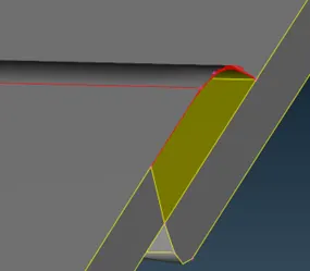
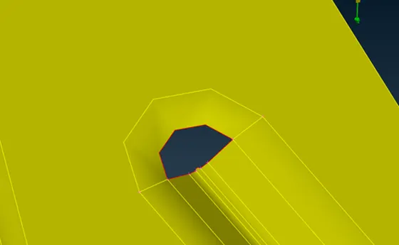
Some of the errors like unchecked faces are cleared manually using commands Faces > Delete and Faces > New > Fitted/CONS.
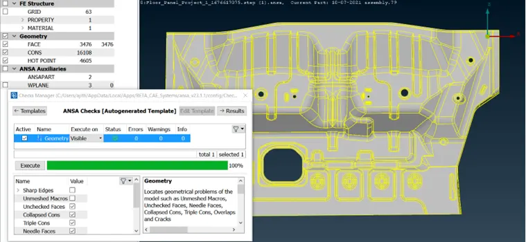
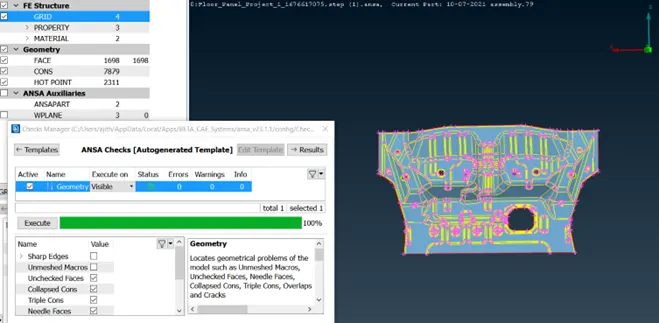
When all the errors are cleared manually, the component checked again for geometry and now it is executed with Zero errors as below.
Then the command Faces > Orient is used to check the orientation assigned properly to all the faces of model.
<!-- [if !supportLists]--> III. <!--[endif]-->Mid surface extraction:
Before extracting the mid surface of the component, it is important to find the thickness of the given model. Used command Utilities > Measure and measured random areas in and around the component and found that the panel is 1mm throughout the component.
Later I extracted the mid surface of the component using command Faces > Mid-surface > Skin and then clicking a face to offset the surfaces by 0.5mm.
Created mid surface successfully and then material property applied to the mid surface by the command Macros > Set PID > Faces/Shells and by selecting all the faces using right click and then middle click to open the property window.
Here by clicking left click > New > PSHELL , property window opened and updated the thickness, material, name and colour for the mid surface and then applied it to the opened mid surface as below.
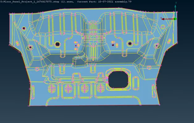
Again executed geometry check for the mid surface to find cracked faces and other unclean issues. Cleared the check with Zero error again as below.
<!-- [if !supportLists]--> IV. <!--[endif]-->Applying Quality criteria and mesh parameters:
To make the mesh component more effective, some quality criteria’s to be assigned for the mid surface component. Once the mid surface is generated, the quality criteria for the mesh is defined using the command Utilities > Quality Criteria or simply clicking F11 takes you to the screen to fill the parameters as per given quality criteria as below.
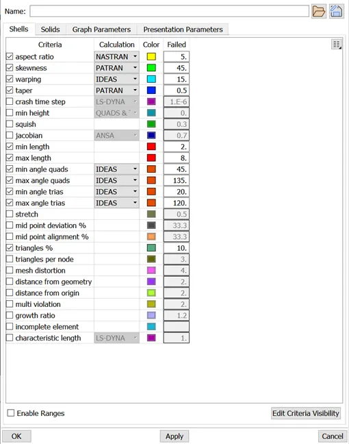
And then switched to the tab Presentation parameters in graphic section, checked the element % and arranged the Details on demand effect as “More details” and then Apply > ok. Also, I saved the criteria for future reference in local folder.
By following the same, I changed mesh parameters using Utilities > Mesh parameters gave the target length of 5mm and changed following setup in the mesh parameters window and saved this also for future reference in local folder.
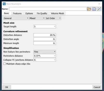
To get a smooth surface on mesh, changed Perimeters > Length command and selected entire component to give the target length of mesh value as 5mm (User can give any value in lower for better mesh).
<!-- [if !supportLists]--> V. <!--[endif]-->Meshing:
Once the quality parameters set for the model, started to generate mesh using the tool Mesh Generation > Best by selecting the faces one by one.
Below checkpoints are followed while meshing the component: -
<!-- [if !supportLists]-->§ <!--[endif]-->Quality check using the option Display styles > Hidden which highlights the given quality criteria are under target value or not in different colours.
<!-- [if !supportLists]-->§ <!--[endif]-->Tria elements pointing the radius, fillets and perimeters are updated using the option Shell mesh > Reconstruct
<!-- [if !supportLists]-->§ <!--[endif]-->Clean and smooth mesh elements on larger faces by creating face cut options.
<!-- [if !supportLists]-->§ <!--[endif]-->Unwanted cons were removed while meshing each faces for an effective mesh generation.
<!-- [if !supportLists]-->§ <!--[endif]-->Re-shaped tria and larger elements using command Elements > Split/Swap.
<!-- [if !supportLists]-->§ <!--[endif]-->changing odd number of elements to even number using Perimeter > Number > select > change to even numbers
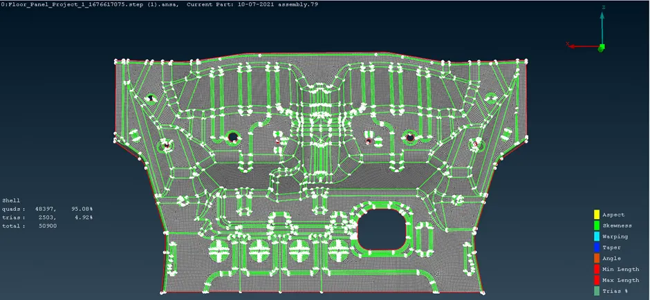
At last, the component is meshed as below with functional commands.
I have enclosed the ANSA file in below drive link as the report submission not allowing me to upload the files
https://drive.google.com/file/d/1jLtChZPi23o-68_pezJrXGqhGC6plxVS/view?usp=sharing