Project 1 - Meshing of Floor Panel
Report
Floor panel
Objective
• To check the geometry error and meshing of all the surfaces with given quality criteria.
• Use classical beast mesh for meshing all the surfaces of the component.
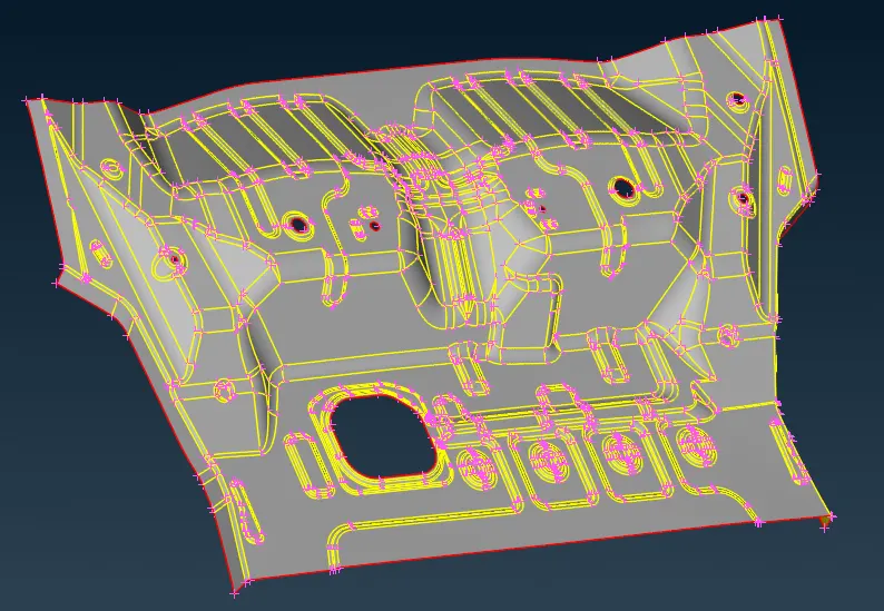
CAD Model
• This is the picture of the CAD model
Procedure
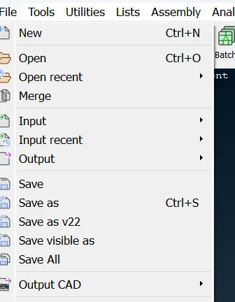
• Browse the CAD file for this go to file and choose open.
• select the file location and open the file
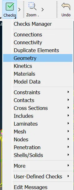
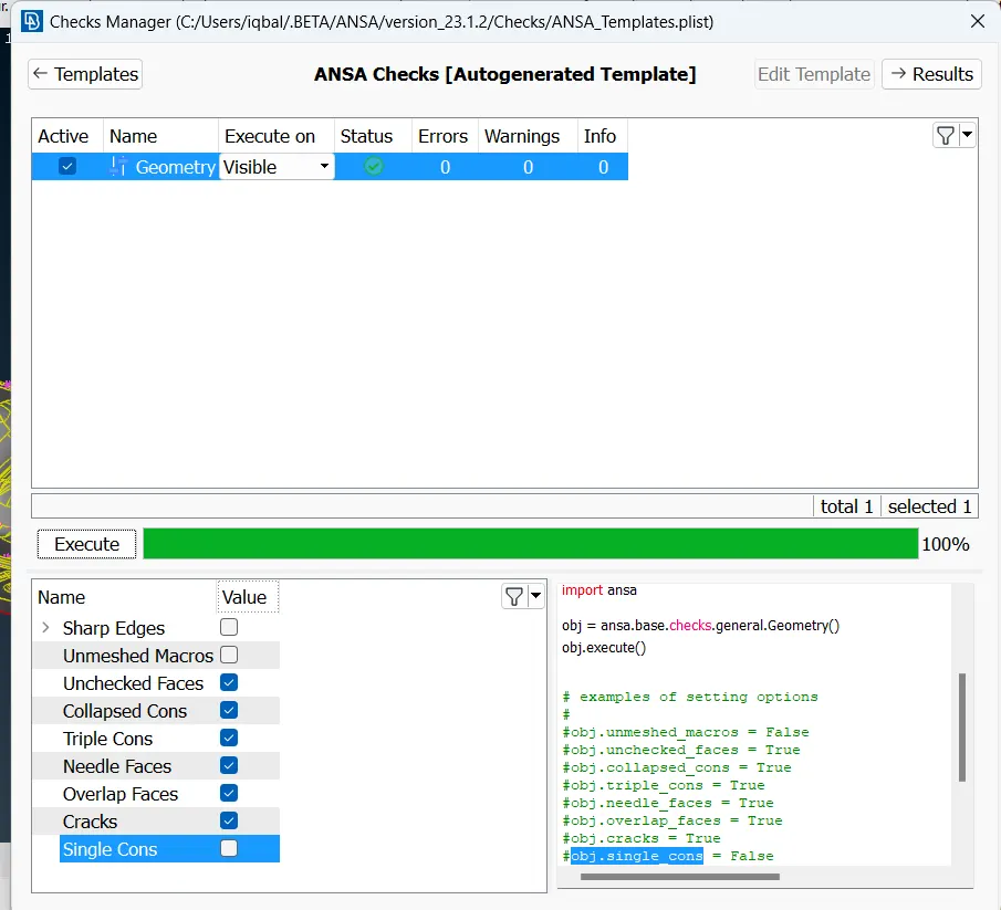
• After opening the file click on checks and select geometry then execute.
• Remove the geometry error from the CAD model(by using topo).
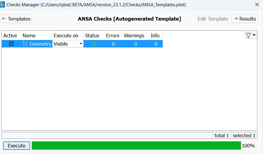
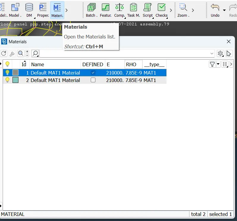
• Then assign the Material to the component, for that click on the material and tick the box to define a material.
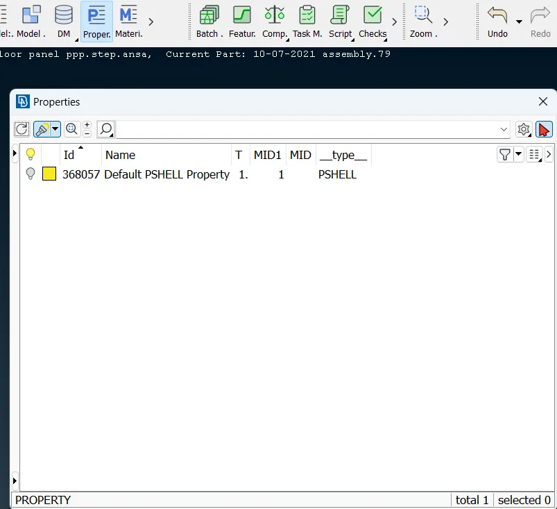
• Now set property click on property and double click on the default PSHELL property this is the default type we can customize.
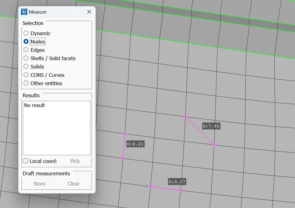
• Now check the thickness of the component by clicking on the measure select nodes option and select the two opposite nodes of the component.
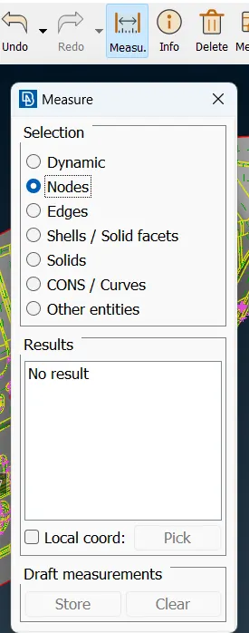
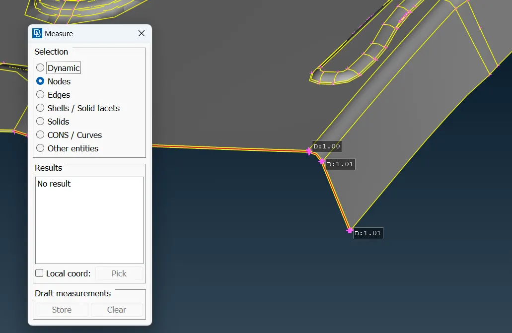
• the dimensions shown in the picture show uniform thickness(more or less 1 mm)which means this model is a sheet metal component.
• Now extract the mid surface of the component by using the manual method for that click on offset.
• before doing that apply orient on the face of the component so that it changes the color of the component to gray and yellow.
• Gray color shows positive signs and yellow color shows negative signs.
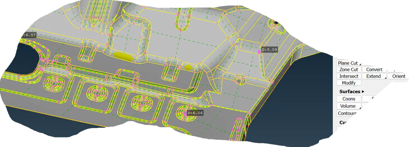
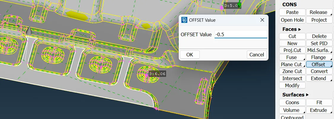
• just press OK then use the INOT command to select that mid-surface generated here and press invert to get a segment of mid-surface
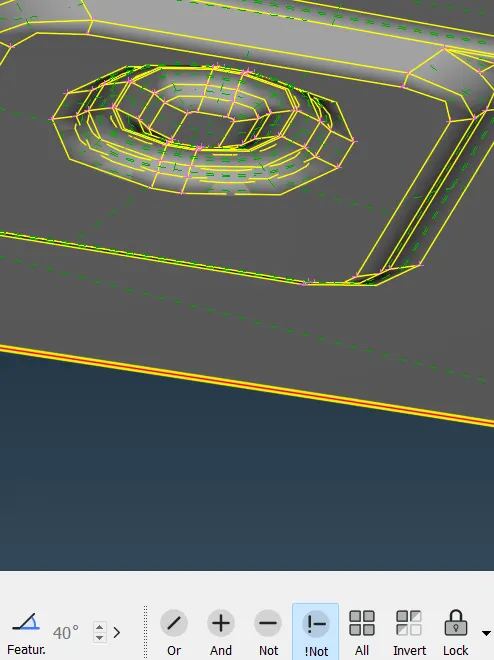
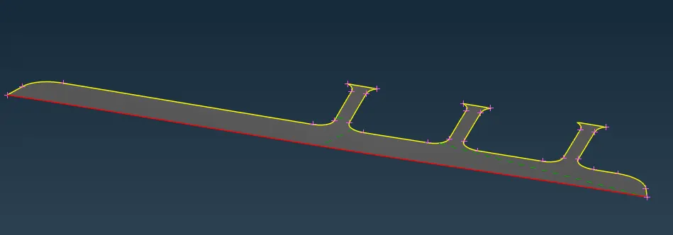
• now lock the view and use the OR and neighbor all commands to get more surfaces related to the edges.
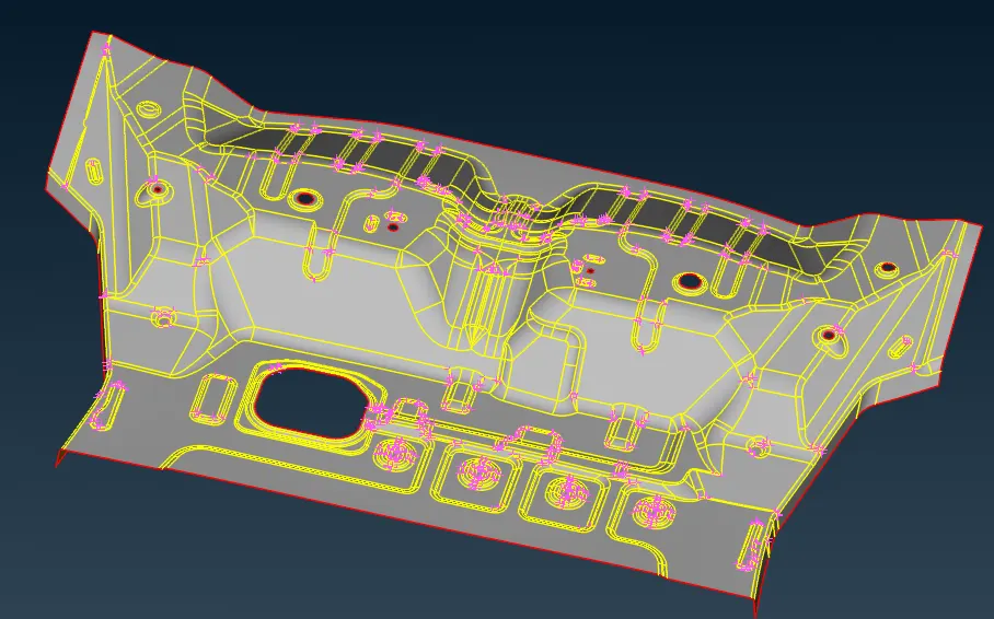
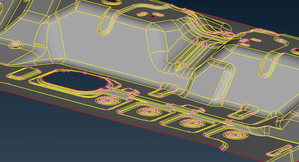
• now again check geometry error apart from single cons no error will occur.
• now set the Quality Criteria
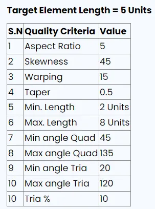
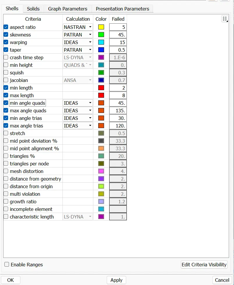
• now go to quality or use the F11 short key and set the given quality parameter that is shown in the picture then press apply and press OK.
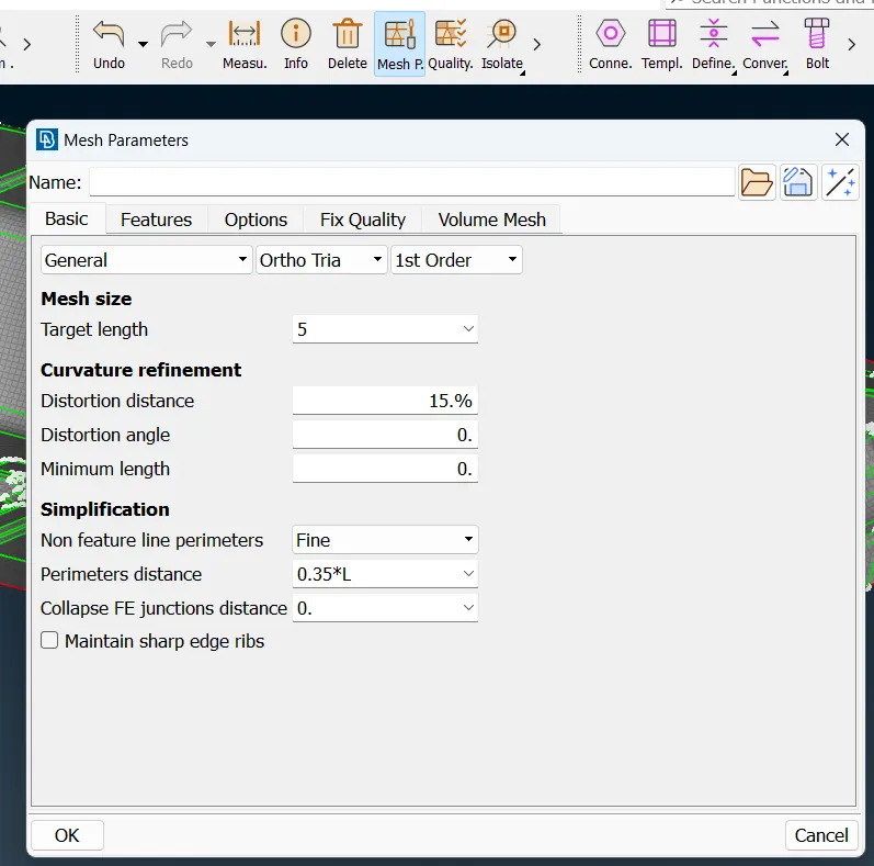
Meshing
• now go to the mesh parameter to set up the target element length shown in the picture.
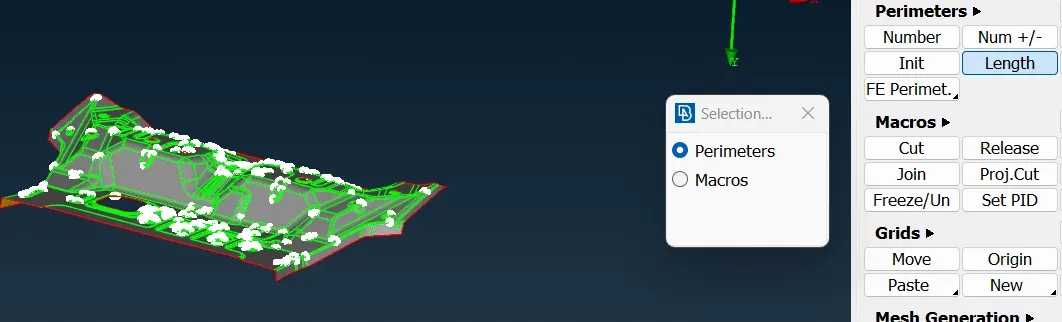
• go to classic mates click on length and apply perimeter and micro length on the entire geometry.
• now set PID for mid-surface too.
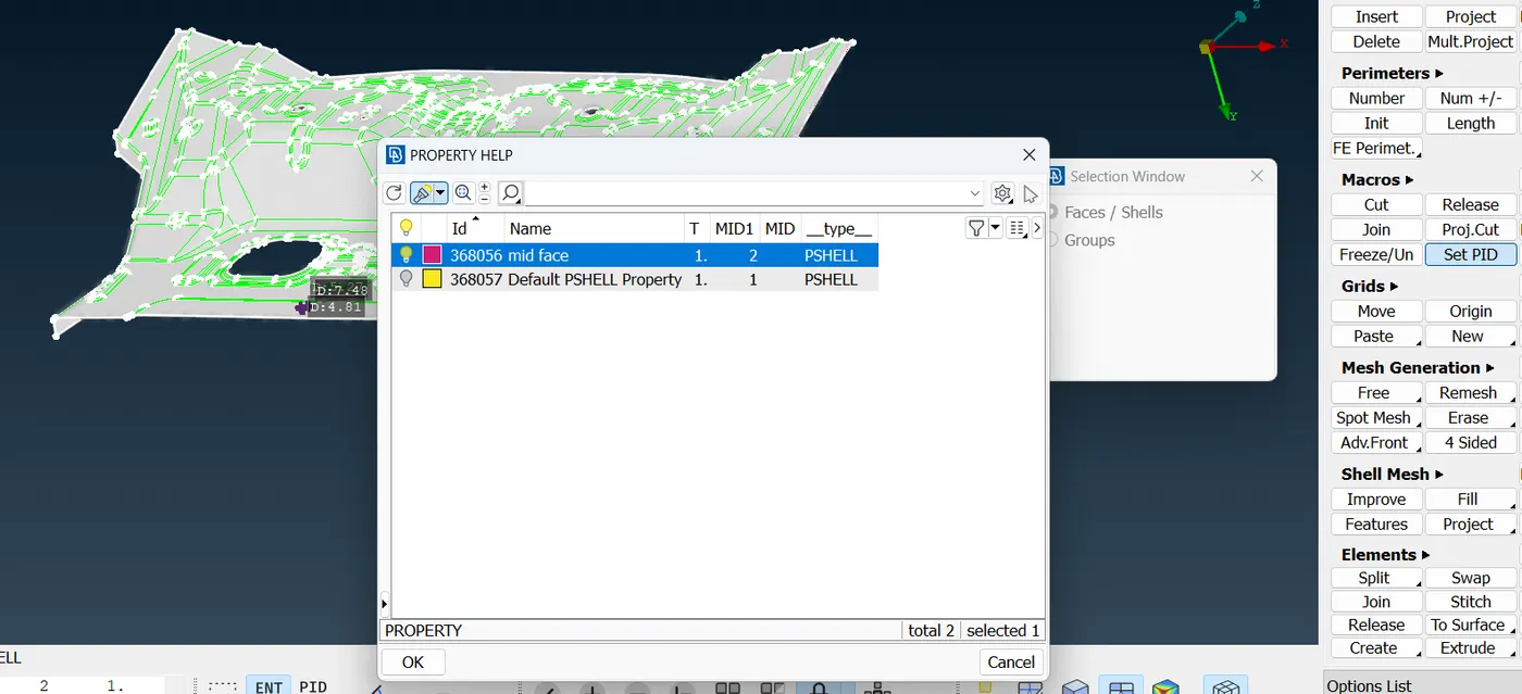
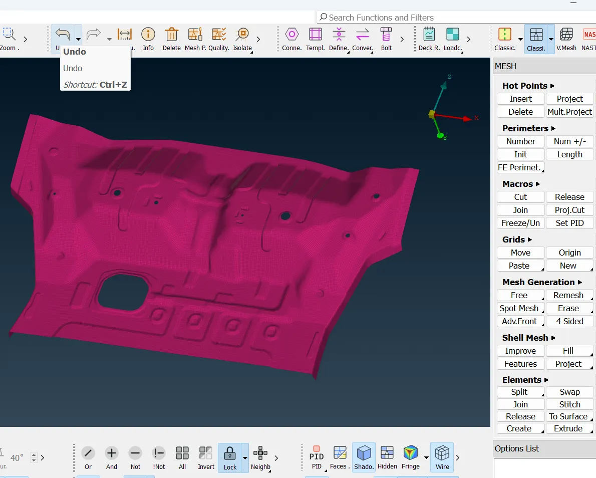
• then use BEST mesh on the face of the component.
• after doing this we get meshing on entire surfaces.
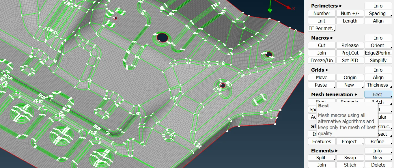
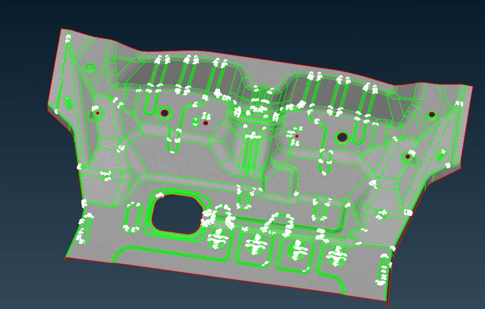
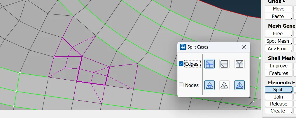
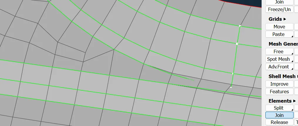
• then use split and join the command to reduce the tria element from the component.
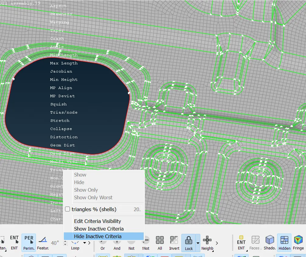
• click on the hidden mode option to check the all quality criteria
• no quality error is found.
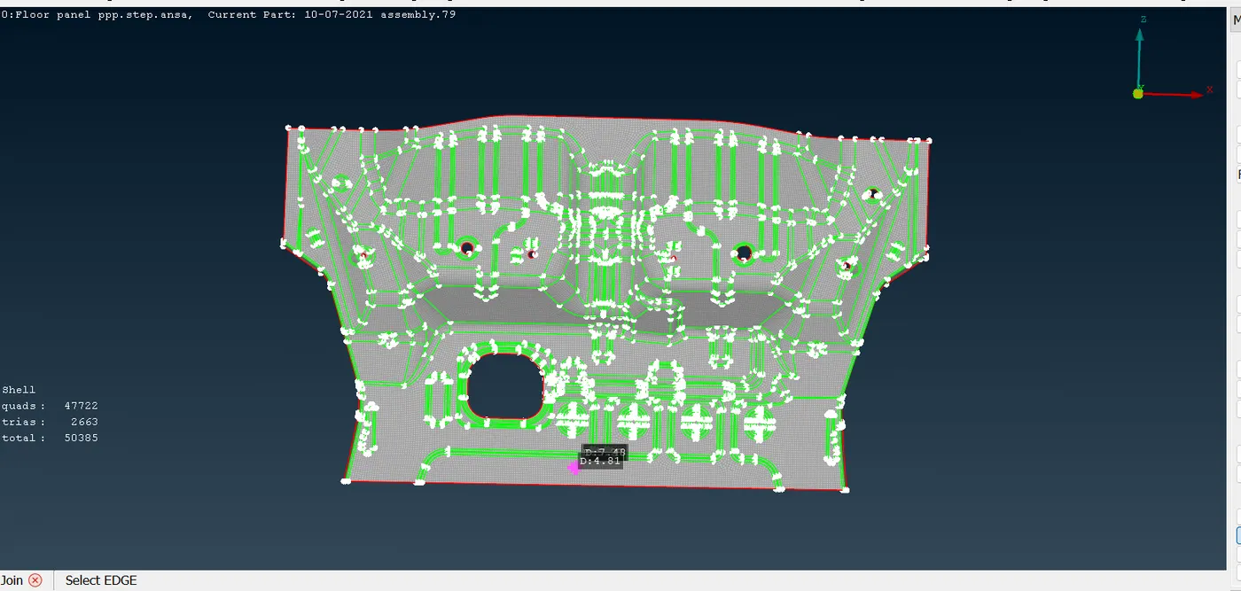
• randomly checking the quality parameter on the meshing surface.